CN112873030B - Manufacturing and processing technology of hard alloy shaft sleeve - Google Patents
Manufacturing and processing technology of hard alloy shaft sleeve Download PDFInfo
- Publication number
- CN112873030B CN112873030B CN202110266044.9A CN202110266044A CN112873030B CN 112873030 B CN112873030 B CN 112873030B CN 202110266044 A CN202110266044 A CN 202110266044A CN 112873030 B CN112873030 B CN 112873030B
- Authority
- CN
- China
- Prior art keywords
- shaft sleeve
- frame
- clamping
- install
- rod
- Prior art date
- Legal status (The legal status is an assumption and is not a legal conclusion. Google has not performed a legal analysis and makes no representation as to the accuracy of the status listed.)
- Active
Links
Images


Classifications
-
- B—PERFORMING OPERATIONS; TRANSPORTING
- B24—GRINDING; POLISHING
- B24B—MACHINES, DEVICES, OR PROCESSES FOR GRINDING OR POLISHING; DRESSING OR CONDITIONING OF ABRADING SURFACES; FEEDING OF GRINDING, POLISHING, OR LAPPING AGENTS
- B24B29/00—Machines or devices for polishing surfaces on work by means of tools made of soft or flexible material with or without the application of solid or liquid polishing agents
- B24B29/02—Machines or devices for polishing surfaces on work by means of tools made of soft or flexible material with or without the application of solid or liquid polishing agents designed for particular workpieces
- B24B29/06—Machines or devices for polishing surfaces on work by means of tools made of soft or flexible material with or without the application of solid or liquid polishing agents designed for particular workpieces for elongated workpieces having uniform cross-section in one main direction
- B24B29/08—Machines or devices for polishing surfaces on work by means of tools made of soft or flexible material with or without the application of solid or liquid polishing agents designed for particular workpieces for elongated workpieces having uniform cross-section in one main direction the cross-section being circular, e.g. tubes, wires, needles
-
- B—PERFORMING OPERATIONS; TRANSPORTING
- B24—GRINDING; POLISHING
- B24B—MACHINES, DEVICES, OR PROCESSES FOR GRINDING OR POLISHING; DRESSING OR CONDITIONING OF ABRADING SURFACES; FEEDING OF GRINDING, POLISHING, OR LAPPING AGENTS
- B24B41/00—Component parts such as frames, beds, carriages, headstocks
- B24B41/02—Frames; Beds; Carriages
-
- B—PERFORMING OPERATIONS; TRANSPORTING
- B24—GRINDING; POLISHING
- B24B—MACHINES, DEVICES, OR PROCESSES FOR GRINDING OR POLISHING; DRESSING OR CONDITIONING OF ABRADING SURFACES; FEEDING OF GRINDING, POLISHING, OR LAPPING AGENTS
- B24B41/00—Component parts such as frames, beds, carriages, headstocks
- B24B41/04—Headstocks; Working-spindles; Features relating thereto
-
- B—PERFORMING OPERATIONS; TRANSPORTING
- B24—GRINDING; POLISHING
- B24B—MACHINES, DEVICES, OR PROCESSES FOR GRINDING OR POLISHING; DRESSING OR CONDITIONING OF ABRADING SURFACES; FEEDING OF GRINDING, POLISHING, OR LAPPING AGENTS
- B24B41/00—Component parts such as frames, beds, carriages, headstocks
- B24B41/06—Work supports, e.g. adjustable steadies
- B24B41/067—Work supports, e.g. adjustable steadies radially supporting workpieces
-
- B—PERFORMING OPERATIONS; TRANSPORTING
- B24—GRINDING; POLISHING
- B24B—MACHINES, DEVICES, OR PROCESSES FOR GRINDING OR POLISHING; DRESSING OR CONDITIONING OF ABRADING SURFACES; FEEDING OF GRINDING, POLISHING, OR LAPPING AGENTS
- B24B47/00—Drives or gearings; Equipment therefor
- B24B47/10—Drives or gearings; Equipment therefor for rotating or reciprocating working-spindles carrying grinding wheels or workpieces
- B24B47/12—Drives or gearings; Equipment therefor for rotating or reciprocating working-spindles carrying grinding wheels or workpieces by mechanical gearing or electric power
-
- B—PERFORMING OPERATIONS; TRANSPORTING
- B24—GRINDING; POLISHING
- B24B—MACHINES, DEVICES, OR PROCESSES FOR GRINDING OR POLISHING; DRESSING OR CONDITIONING OF ABRADING SURFACES; FEEDING OF GRINDING, POLISHING, OR LAPPING AGENTS
- B24B47/00—Drives or gearings; Equipment therefor
- B24B47/20—Drives or gearings; Equipment therefor relating to feed movement
-
- B—PERFORMING OPERATIONS; TRANSPORTING
- B24—GRINDING; POLISHING
- B24B—MACHINES, DEVICES, OR PROCESSES FOR GRINDING OR POLISHING; DRESSING OR CONDITIONING OF ABRADING SURFACES; FEEDING OF GRINDING, POLISHING, OR LAPPING AGENTS
- B24B47/00—Drives or gearings; Equipment therefor
- B24B47/22—Equipment for exact control of the position of the grinding tool or work at the start of the grinding operation
Abstract
The invention provides a hard alloy shaft sleeve manufacturing and processing technology which comprises an inner clamp rotating mechanism, a lower contact mechanism and a clamping mechanism, wherein the inner clamp rotating mechanism is installed on the clamping mechanism, the lower contact mechanism is arranged right above the inner clamp rotating mechanism, and the lower contact mechanism is installed on the clamping mechanism; the invention solves the problems that most polishing and grinding treatment aiming at the shaft sleeve is carried out by manually using tools, the mode is time-consuming and labor-consuming, batch grinding treatment is difficult to carry out on the hard alloy shaft sleeve, the working efficiency is lower, the grinding process of the shaft sleeve cannot be effectively clamped and stabilized, the grinding effect is not ideal, the use requirement is difficult to achieve and the like.
Description
Technical Field
The invention relates to the technical field of shaft sleeves, in particular to a manufacturing and processing technology of a hard alloy shaft sleeve.
Background
The shaft sleeve is a cylindrical mechanical part sleeved on the rotating shaft and is a component of a sliding bearing, generally, the shaft sleeve is in interference fit with a bearing seat and in clearance fit with the shaft, and hard alloy shaft sleeve series products are widely used in modern production and manufacturing industries due to excellent performances of high temperature resistance, corrosion resistance, wear resistance and the like;
after the production and the manufacture of the hard alloy shaft sleeve, in order to reduce the surface roughness and the friction coefficient, the inner surface and the outer surface of the shaft sleeve need to be polished and ground, so that the specific surface roughness is obtained, and the service performance and the quality of the shaft sleeve are improved; polishing and grinding treatment aiming at the shaft sleeve is mostly carried out by manually using tools, the mode is time-consuming and labor-consuming, batch polishing treatment is difficult to carry out on the hard alloy shaft sleeve, the working efficiency is low, the grinding process of the shaft sleeve cannot be effectively clamped and stabilized, the grinding effect is not ideal, and the use requirement is difficult to meet; therefore, the invention provides a manufacturing and processing technology of a hard alloy shaft sleeve.
Disclosure of Invention
In order to achieve the purpose, the invention adopts the following technical scheme that the manufacturing and processing technology of the hard alloy shaft sleeve uses a hard alloy shaft sleeve manufacturing and processing device which comprises an internal clamping rotating mechanism, a downward contact mechanism and a clamping mechanism, and the specific method for polishing and grinding the inner surface and the outer surface of the hard alloy shaft sleeve by adopting the manufacturing and processing device is as follows:
s1, blank processing: selecting a high-temperature-resistant, corrosion-resistant and wear-resistant hard alloy bar, and turning the hard alloy bar by a numerical control machine tool to manufacture a shaft sleeve;
s2, polishing and grinding the inner wall of the shaft sleeve: clamping the shaft sleeve prepared in the step S1 through a clamping mechanism, adjusting an inner sand touching plate to be in contact with the inner wall of the shaft sleeve, and then polishing and grinding the inner wall of the shaft sleeve through rotating an inner clamp grinding unit;
s3, polishing and grinding the surface of the shaft sleeve: the shaft sleeve is fixedly clamped by adjusting the abutting force of the inner clamp polishing unit on the inner wall of the shaft sleeve, the clamping mechanism is released to rotate the shaft sleeve, and then the surface of the shaft sleeve is abutted and polished by the lower contact mechanism;
s4, heat treatment arrangement: the shaft sleeve after being polished is subjected to heat treatment processing by workers, so that the structure performance of the shaft sleeve is changed, and the high-temperature resistance, corrosion resistance and wear resistance of the shaft sleeve are enhanced;
the clamping mechanism is provided with an inner clamping rotating mechanism, a lower contact mechanism is arranged right above the inner clamping rotating mechanism, and the lower contact mechanism is arranged on the clamping mechanism;
the inner clamp rotating mechanism comprises a vertical plate stand, an inner clamp polishing unit, a belt wheel, a linkage belt and a motor; the vertical plate stand is arranged on the clamping mechanism, a plurality of groups of inner clamping polishing units which are linearly distributed along the length direction of the vertical plate stand are arranged on the vertical plate stand through bearings, belt wheels are arranged at the outer side shaft ends of the inner clamping polishing units, the belt wheels are mutually connected through a linkage belt arranged on an outer ring in a transmission manner, the motor is arranged on the outer wall of the vertical plate stand through a motor base, and an output shaft of the motor is mutually connected with the belt wheels at the outer end of the left side through a coupler;
the internal clamp polishing unit comprises a cross rod connecting frame, a positioning disc, a floating guide rail, an ejector rod, a cylindrical spring, a guide disc, an internal sand touching plate, a rotating wheel lead screw, a displacement pumping rod, a triangular circular frame and a roller; the device comprises a vertical plate vertical frame, a transverse rod connecting frame, positioning discs, ejector rods, guide discs, a rotary wheel lead screw, a displacement pumping rod, a triangular roller wheel connecting frame and a plurality of triangular rollers, wherein the transverse rod connecting frame is arranged on the vertical plate vertical frame through a bearing, the two positioning discs are linearly distributed along the length direction of the transverse rod connecting frame, a plurality of floating guide rails are arranged on the positioning discs in a sliding fit mode, the plurality of floating guide rails are annularly distributed along the circumferential direction of the positioning discs, the ejector rods are connected with the positioning discs in a sliding fit mode, the top shaft ends of the ejector rods are connected with the inner sand contact plates, the guide discs are arranged between the two positioning discs, the guide discs are arranged on the transverse rod connecting frame, the plurality of inner sand contact plates are annularly distributed along the circumferential direction of the guide discs are arranged on the guide discs in a sliding fit mode, the rotary wheel lead screw is arranged on the transverse rod connecting frame in a thread fit mode, the inner side of the rotary wheel lead screw is connected with one shaft end of the displacement pumping rod through a bearing, the displacement pumping rod is arranged on the transverse rod connecting frame in a sliding fit mode, the displacement pumping rod is respectively connected with the positioning discs and the guide discs in a triangular roller wheel connecting frame in a rolling fit mode, and the plurality of rollers are arranged on the circular roller wheels in a triangular roller wheel connecting frame in a triangular roller wheel connecting mode; the rotary wheel lead screw is swung to push the displacement drawing rod to move in a sliding manner, so that the roller on the triangular circular frame synchronously rolls to push against the floating guide rail, the ejector rod pushes the inner sand-contacting plate to move outwards, the inner sand-contacting plate is contacted with the inner wall of the shaft sleeve, the floating guide rail is always in close contact with the roller through the cylindrical spring, and then the motor drives the belt pulley to drive the linkage belt to rotate, so that the transverse rod connecting frame synchronously rotates, and polishing operation is performed.
Preferably, the lower touch mechanism comprises a hanger and a lower touch unit; the hanger is arranged on the clamping mechanism and provided with a plurality of downward contact units which are linearly distributed along the length direction of the hanger;
preferably, the lower touch unit comprises a frame, a rocking wheel screw, a limiting sliding plate, a pulley, a sliding rod, a compression spring, an outer sand touch plate and a guide rod; the frame is installed on the inner wall of the top end of the hanger, the rocking wheel screw rod is installed on the outer wall of the frame in a thread matching mode, the shaft end on the inner side of the rocking wheel screw rod is connected with the limiting sliding plate through a bearing, the limiting sliding plate is installed on the inner wall of the top end of the frame in a sliding matching mode, a pulley is arranged right below the limiting sliding plate and connected with the limiting sliding plate through a rolling mode, the pulley is installed on the shaft end on the top of the sliding rod through the bearing, a compression spring is arranged on the outer ring of the sliding rod, the sliding rod is installed on the frame in a sliding matching mode, an outer sand contact plate is installed at the shaft end on the bottom of the sliding rod, guide rods are arranged on the outer side of the sliding rod, the guide rods are symmetrically installed on the frame in a sliding matching mode, and the shaft ends on the bottom of the guide rods are connected with the outer sand contact plate; the limiting sliding plate is rotationally supported and pushed to translate through the rocking wheel screw rod, the limiting sliding plate is enabled to translate and slide to support and push the pulley, the pulley is enabled to be in close contact with the limiting sliding plate through the compression spring, the sliding rod is enabled to descend, and the guide rod vertically guides the outer sand touching plate to descend and move.
Preferably, the clamping mechanism comprises a platform bracket, a slide rail, a clamping sliding frame, a rotary seat, a two-position lead screw and a hand wheel; the end face of the platform support is symmetrically provided with slide rails, the slide rails are provided with a plurality of groups of clamping sliding frames which are linearly distributed along the length direction of the slide rails in a sliding fit mode, rotary seats are arranged on the outer sides of the clamping sliding frames, the rotary seats are arranged on the edge of the end face of the platform support in bilateral symmetry, a double-position lead screw is arranged between the two rotary seats through a bearing, the double-position lead screw is mutually connected with the clamping sliding frames in a threaded fit mode, and a hand wheel is arranged on one side shaft end of the double-position lead screw; the double-position lead screw is rotated by the hand wheel, so that the clamping sliding frame is synchronously translated in opposite directions, and the shaft sleeve is clamped and fixed.
Preferably, the inner side end face of the floating guide rail is designed to be inclined from low to high, and the inner side end face of the floating guide rail is designed to be inclined from low to high, so that the roller rolls to abut against the inner side end face of the floating guide rail, and the sand touching plate can move and be adjusted practically, and the grinding requirement without diameter size shaft sleeves can be met.
Preferably, the displacement is taken out and is provided with a plurality of recesses that are the annular and distribute along its circumferencial direction on the pole, will the displacement take out and be provided with a plurality of recesses that are the annular and distribute along its circumferencial direction on the pole, be convenient for realize the horizontal linear translation of displacement and take out the pole and slide, can prevent rocking when the rotatory operation of polishing.
Preferably, the terminal surface of being connected of spacing slide and pulley is for designing from low to high slope, and through the unsmooth cooperation mode interconnect of V type between spacing slide and the pulley, will spacing slide establishes to the design from low to high slope with the terminal surface of being connected of pulley, and through the unsmooth cooperation mode interconnect of V type between spacing slide and the pulley, is convenient for turn into the elevating movement of vertical direction with translational motion, satisfies the regulation demand that the outer sand touching board contradicted the axle sleeve position of polishing, and can stabilize the surface that the outer sand touching board contradicted the axle sleeve of polishing through the unsmooth cooperation mode interconnect of V type, prevents that the axle sleeve from when touching the sand board outside rotatory butt, leads to being connected of pulley and spacing slide to rock, makes the contact of polishing unstable.
Preferably, the centre gripping mouth of pressing from both sides the balladeur train is V type structural design, will the centre gripping mouth of pressing from both sides the balladeur train establishes to V type structural design, and the different diameter size's of centre gripping axle sleeve is convenient for increase through V type structural design and can the centre gripping scope to cooperate the diameter size of axle sleeve and carry out the centre gripping, make centre gripping application scope increase.
The invention has the beneficial effects that:
1. according to the invention, the inner walls of the shaft sleeves can be synchronously ground in batch through the inner clamp rotating mechanism, the grinding treatment of the shaft sleeves with different diameters is met, the shaft sleeves are fixedly clamped by adjusting the contact force of the inner clamp grinding unit on the inner walls of the shaft sleeves, the clamping mechanism is released to rotate the shaft sleeves, then the surface of the shaft sleeves is pressed and ground through the lower contact mechanism, the polishing and grinding treatment of the surface of the shaft sleeves is realized, the grinding and polishing treatment can be carried out on the inner and outer walls of the shaft sleeves, the clamping steps of the shaft sleeves are reduced, and the coaxiality of the shaft sleeves after grinding is effectively improved.
2. According to the invention, the lower touch mechanism is used for controlling the surface of the contact shaft sleeve, so that the contact grinding operation of the surfaces of the shaft sleeves with different diameters can be met, the operation range of polishing and grinding is enlarged, and the surface of the shaft sleeve is subjected to polishing and grinding treatment, so that the specific surface roughness is obtained, and the surface of the shaft sleeve is smoother, more attractive and meets the use requirement.
3. According to the shaft sleeve clamping mechanism, the clamping requirements of shaft sleeves with different diameters are met through the clamping mechanism, and the shaft sleeves are clamped by matching with the diameters of the shaft sleeves, so that the clamping application range is enlarged, the shaft sleeves can be clamped and fixed in batches, the clamping efficiency is improved, the grinding and polishing operation aiming at the plurality of shaft sleeves can be synchronously realized, and the batch operation efficiency is improved.
Drawings
The invention is further illustrated with reference to the following figures and examples.
FIG. 1 is a schematic view of a manufacturing process of a cemented carbide sleeve according to the present invention;
FIG. 2 is a perspective view of the present invention in a primary viewing position;
FIG. 3 is an enlarged view of a portion of the invention at A in FIG. 2;
FIG. 4 is a perspective view of the present invention in a rear-view position;
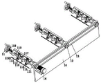
FIG. 5 is a perspective view of the internal clamping and rotating mechanism of the present invention;
FIG. 6 is a schematic perspective view of an inner nip grinding unit of the present invention;
fig. 7 is a partial enlarged view of the invention at B in fig. 6.
Detailed Description
In order to make the technical means, the creation features, the achievement purposes and the effects of the invention easy to understand, the invention is further described below by combining with the specific drawings, and it is to be noted that the embodiments and the features in the embodiments can be combined with each other in the application without conflict.
As shown in fig. 1 to 7, a process for manufacturing and processing a hard alloy shaft sleeve uses a hard alloy shaft sleeve manufacturing and processing device, which includes an inner clamping rotating mechanism, a lower contact mechanism and a clamping mechanism 3, and the specific method for polishing and grinding the inner and outer surfaces of the hard alloy shaft sleeve by using the above manufacturing and processing device is as follows:
s1, blank processing: selecting a high-temperature-resistant, corrosion-resistant and wear-resistant hard alloy bar, and turning the hard alloy bar by a numerical control machine tool to manufacture a shaft sleeve;
s2, polishing and grinding the inner wall of the shaft sleeve: clamping the shaft sleeve prepared in the step S1 through a clamping mechanism 3, adjusting an inner sand touching plate 117 to be in contact with the inner wall of the shaft sleeve, and polishing and grinding the inner wall of the shaft sleeve through a rotary inner clamping grinding unit 11;
s3, polishing and grinding the surface of the shaft sleeve: the shaft sleeve is fixedly clamped by adjusting the abutting force of the inner clamp polishing unit 11 on the inner wall of the shaft sleeve, the clamping mechanism 3 is released to rotate the shaft sleeve, and then the surface of the shaft sleeve is abutted and polished by the lower contact mechanism;
s4, heat treatment arrangement: the shaft sleeve after being polished is subjected to heat treatment processing by workers, so that the structure performance of the shaft sleeve is changed, and the high-temperature resistance, corrosion resistance and wear resistance of the shaft sleeve are enhanced;
the clamping mechanism 3 is provided with an inner clamping rotating mechanism, a lower contact mechanism is arranged right above the inner clamping rotating mechanism, and the lower contact mechanism is arranged on the clamping mechanism 3;
the inner clamp rotating mechanism comprises a vertical plate stand 10, an inner clamp polishing unit 11, a belt wheel 12, a linkage belt 13 and a motor 14; the vertical plate stand 10 is arranged on a platform support 30, a plurality of groups of inner clamping polishing units 11 which are linearly distributed along the length direction of the vertical plate stand 10 are arranged on the vertical plate stand 10 through bearings, belt wheels 12 are arranged at the outer side shaft ends of the inner clamping polishing units 11, the belt wheels 12 are mutually connected through a linkage belt 13 arranged on an outer ring in a transmission manner, a motor 14 is arranged on the outer wall of the vertical plate stand 10 through a motor base, and an output shaft of the motor 14 is mutually connected with the belt wheel 12 at the outer end of the left side through a coupling;
the internal clamp polishing unit 11 comprises a cross rod connecting frame 111, a positioning disc 112, a floating guide rail 113, a top rod 114, a cylindrical spring 115, a guide disc 116, an internal sand touching plate 117, a rotating wheel screw rod 118, a displacement pumping rod 119, a triangular circular frame 119A and a roller 119B; the cross bar connecting frame 111 is installed on the vertical plate stand 10 through a bearing, two positioning circular discs 112 which are linearly distributed along the length direction of the cross bar connecting frame 111 are arranged on the cross bar connecting frame 111, a plurality of floating guide rails 113 which are annularly distributed along the circumferential direction of the positioning circular discs 112 are arranged on the positioning circular discs 112 in a sliding fit mode, the inner side end faces of the floating guide rails 113 are designed to be inclined from low to high, and rollers 119B are convenient to roll and abut against the inner side end faces of the floating guide rails 113, so that the sand touching plate 117 can be moved and adjusted practically, and the polishing requirements of shaft sleeves with different diameters can be met; a top rod 114 is arranged on the outer end surface of the floating guide rail 113, a cylindrical spring 115 is arranged on the outer ring of the top rod 114, the top rod 114 is connected with the positioning disks 112 in a sliding fit manner, the top shaft end of the top rod 114 is connected with an inner sand-touching plate 117, a guide disk 116 is arranged between the two positioning disks 112, the guide disk 116 is arranged on the cross rod connecting frame 111, the guide disk 116 is provided with a plurality of inner sand-touching plates 117 which are annularly distributed along the circumferential direction thereof in a sliding fit manner, the rotary screw 118 is arranged on the cross rod connecting frame 111 in a thread fit manner, the inner shaft end of the rotary screw 118 is connected with one shaft end of a displacement drawing rod 119 through a bearing, the displacement drawing rod 119 is arranged on the cross rod connecting frame 111 in a sliding fit manner, the displacement drawing rod 119 is respectively connected with the positioning disks 112 and the guide disks 116 in a sliding fit manner, the displacement drawing rod 119 is provided with a plurality of grooves which are annularly distributed along the circumferential direction thereof, the displacement drawing rod 119 is provided with a plurality of grooves which are annularly distributed along the circumferential direction, so as to facilitate the linear sliding movement of the drawing rod, and to prevent the horizontal movement of the drawing rod during polishing operation; the displacement draw rod 119 is provided with two triangular circular frames 119A which are linearly distributed along the length direction of the displacement draw rod, the triangular circular frames 119A are provided with a plurality of rollers 119B which are annularly distributed along the circumferential direction of the triangular circular frames 119A through bearings, and the rollers 119B are mutually connected with the floating guide rail 113 in a rolling manner; the rotating wheel screw 118 is rotated to push the displacement pumping rod 119 to move in a sliding manner, so that the roller 119B on the triangular circular frame 119A synchronously rolls to push against the floating guide rail 113, the ejector rod 114 pushes the inner sand contact plate 117 to move outwards, the inner sand contact plate 117 is contacted with the inner wall of the shaft sleeve, the floating guide rail 113 is always in close contact with the roller 119B through the cylindrical spring 115, and the belt wheel 12 is driven by the motor 14 to drive the linkage belt 13 to rotate, so that the cross rod connecting frame 111 synchronously rotates, and polishing operation is executed.
The lower contact mechanism comprises a hanger 20 and a lower contact unit 21; the hanger 20 is installed on the platform bracket 30, and the hanger 20 is provided with a plurality of lower contact units 21 which are linearly distributed along the length direction of the hanger 20;
the lower touch unit 21 comprises a frame 211, a rocking wheel screw 212, a limiting sliding plate 213, a pulley 214, a sliding rod 215, a compression spring 216, an outer sand touch plate 217 and a guide rod 218; the frame 211 is arranged on the inner wall of the top end of the hanger 20, the rocking wheel screw 212 is arranged on the outer wall of the frame 211 in a thread fit mode, the shaft end on the inner side of the rocking wheel screw 212 is connected with the limiting sliding plate 213 through a bearing, the limiting sliding plate 213 is arranged on the inner wall of the top end of the frame 211 in a sliding fit mode, the pulley 214 is arranged right below the limiting sliding plate 213, the pulley 214 is connected with the limiting sliding plate 213 in a rolling mode, the connecting end surface of the limiting sliding plate 213 and the pulley 214 is in a low-to-high inclined design, the limiting sliding plate 213 and the pulley 214 are connected in a V-shaped concave-convex fit mode, the translational motion is converted into the lifting motion in the vertical direction, the adjustment requirement of the polishing shaft sleeve position of the external sand contact plate 217 is met, the polishing shaft sleeve surface of the external sand contact plate 217 can be stabilized through the V-shaped concave-convex fit mode, and the external sand contact plate 217 is prevented from rotating and abutting against the external sand contact plate 217, and the connecting sliding plate 213 is connected with the limiting sliding plate 214, so that the polishing shaft sleeve is unstable; the pulley 214 is mounted on the top shaft end of the sliding rod 215 through a bearing, a compression spring 216 is arranged on the outer ring of the sliding rod 215, the sliding rod 215 is mounted on the frame 211 in a sliding fit manner, an outer sand contact plate 217 is mounted at the bottom shaft end of the sliding rod 215, a guide rod 218 is arranged on the outer side of the sliding rod 215, the guide rods 218 are symmetrically mounted on the frame 211 in a sliding fit manner, and the bottom shaft end of the guide rod 218 is connected with the outer sand contact plate 217; the limit sliding plate 213 is pushed to move horizontally by the rotation of the rocking wheel screw 212, the limit sliding plate 213 moves horizontally and slides to push the pulley 214, the pulley 214 is in close contact with the limit sliding plate 213 by the compression spring 216, the sliding rod 215 descends, and the guide rod 218 vertically guides the descending movement of the outer sand touching plate 217.
The clamping mechanism 3 comprises a platform bracket 30, a slide rail 31, a clamping sliding frame 32, a rotary seat 33, a double-position lead screw 34 and a hand wheel 35; the end face of the platform support 30 is symmetrically provided with slide rails 31, the slide rails 31 are provided with a plurality of groups of clamping sliding frames 32 which are linearly distributed along the length direction of the slide rails 31 in a sliding fit manner, the clamping ports of the clamping sliding frames 32 are designed into a V-shaped structure, the clamping ports of the clamping sliding frames 32 are designed into the V-shaped structure, so that shaft sleeves with different diameter sizes can be clamped conveniently, the clamping range can be enlarged through the V-shaped structure, and the clamping is carried out by matching the diameter size of the shaft sleeves, so that the clamping application range is enlarged; a rotary seat 33 is arranged on the outer side of the clamping sliding frame 32, the rotary seats 33 are symmetrically arranged on the edge of the end face of the platform support 30 in the left-right direction, a double-position lead screw 34 is arranged between the two rotary seats 33 through a bearing, the double-position lead screw 34 is mutually connected with the clamping sliding frame 32 in a thread matching mode, and a hand wheel 35 is arranged on the shaft end on one side of the double-position lead screw 34; the hand wheel 35 is used for swinging the double-position lead screw 34, so that the clamping sliding frame 32 synchronously and oppositely translates, and the clamping and fixing of the shaft sleeve are realized.
The foregoing illustrates and describes the principles, general features, and advantages of the present invention. It will be understood by those skilled in the art that the present invention is not limited to the embodiments described above, which are given by way of illustration of the principles of the present invention, and that various changes and modifications may be made without departing from the spirit and scope of the invention as defined by the appended claims. The scope of the invention is defined by the appended claims and equivalents thereof.
Claims (7)
1. The utility model provides a carbide axle sleeve manufacturing and processing technology, its used a carbide axle sleeve manufacturing and processing equipment, should make processing equipment include interior clamp rotating mechanism, touch mechanism and fixture (3) down, its characterized in that: the specific method for polishing and grinding the inner surface and the outer surface of the hard alloy shaft sleeve by adopting the manufacturing and processing equipment comprises the following steps:
s1, blank processing: selecting a high-temperature-resistant, corrosion-resistant and wear-resistant hard alloy bar, and turning the hard alloy bar by a numerical control machine tool to manufacture a shaft sleeve;
s2, polishing and grinding the inner wall of the shaft sleeve: clamping the shaft sleeve prepared in the S1 through a clamping mechanism (3), adjusting an inner sand touching plate (117) to be in contact with the inner wall of the shaft sleeve, and polishing and grinding the inner wall of the shaft sleeve through a rotary inner clamping grinding unit (11);
s3, polishing and grinding the surface of the shaft sleeve: the shaft sleeve is fixedly clamped by adjusting the abutting force of the inner clamp polishing unit (11) on the inner wall of the shaft sleeve, the clamping mechanism (3) is released to rotate the shaft sleeve, and then the surface of the shaft sleeve is abutted and polished by the lower contact mechanism;
s4, heat treatment arrangement: the shaft sleeve after being polished is subjected to heat treatment processing by workers, so that the structure performance of the shaft sleeve is changed, and the high-temperature resistance, corrosion resistance and wear resistance of the shaft sleeve are enhanced;
the clamping mechanism (3) is provided with an inner clamping rotating mechanism, a lower contact mechanism is arranged right above the inner clamping rotating mechanism, and the lower contact mechanism is arranged on the clamping mechanism (3);
the inner clamp rotating mechanism comprises a vertical plate stand (10), an inner clamp polishing unit (11), a belt wheel (12), a linkage belt (13) and a motor (14); the vertical plate stand (10) is arranged on the clamping mechanism (3), a plurality of groups of inner clamping polishing units (11) which are linearly distributed along the length direction of the vertical plate stand (10) are arranged on the vertical plate stand (10) through bearings, belt wheels (12) are arranged at the outer side shaft ends of the inner clamping polishing units (11), the belt wheels (12) are mutually connected through a linkage belt (13) arranged on an outer ring in a transmission manner, the motor (14) is arranged on the outer wall of the vertical plate stand (10) through a motor base, and an output shaft of the motor (14) is mutually connected with the belt wheel (12) at the outer end of the left side through a coupler;
the internal clamp polishing unit (11) comprises a cross rod connecting frame (111), a positioning disc (112), a floating guide rail (113), a top rod (114), a cylindrical spring (115), a guide disc (116), an internal sand touching plate (117), a rotating wheel lead screw (118), a displacement drawing rod (119), a triangular circular frame (119A) and a roller (119B); the horizontal pole allies oneself with frame (111) install on upright plate grudging post (10) through the bearing, horizontal pole allies oneself with frame (111) on be provided with two and be the positioning disc (112) of straight line distribution along its length direction, positioning disc (112) on be provided with a plurality of its circumferencial direction through sliding fit mode and be the unsteady guide rail (113) of annular distribution, be located and install ejector pin (114) on the outside terminal surface of unsteady guide rail (113), the outer lane of ejector pin (114) is provided with cylindrical spring (115), and ejector pin (114) through sliding fit mode and positioning disc (112) interconnect, the top axle head and interior sand touching board (117) interconnect of ejector pin (114), be located two positioning disc (112) between be provided with direction disc (116), guide disc (116) install and connect frame (111) on the horizontal pole, guide disc (116) on be provided with a plurality of interior sand touching plates (117) that are the annular and distribute along its circumferencial direction through sliding fit, runner lead screw (118) install on horizontal pole is connected frame (111) through screw-thread fit, the inboard axle head interconnect that is located runner lead screw (118) passes through bearing and displacement pump rod (119), displacement pump rod (119) install on horizontal pole is connected frame (111) through sliding fit, and displacement pump rod (119) respectively with positioning disc (112) and guide disc (116) interconnect through sliding fit The displacement draw rod (119) on be provided with two triangle circle framves (119A) that are the straight line and distribute along its length direction, triangle circle frame (119A) on be provided with a plurality of gyro wheels (119B) that are the annular and distribute along its circumferencial direction through the bearing, and gyro wheel (119B) through roll mode and floating guide rail (113) interconnect.
2. The manufacturing and processing technology of the hard alloy shaft sleeve according to claim 1, characterized in that: the lower contact mechanism comprises a hanger (20) and a lower contact unit (21); the hanger (20) is arranged on the clamping mechanism (3), and a plurality of lower contact units (21) which are linearly distributed along the length direction of the hanger (20) are arranged on the hanger (20);
the lower touch unit (21) comprises a frame (211), a rocking wheel screw (212), a limiting sliding plate (213), a pulley (214), a sliding rod (215), a compression spring (216), an outer sand touch plate (217) and a guide rod (218); the frame (211) install on gallows (20) top inner wall, be located and install rocking wheel lead screw (212) through screw-thread fit on the outer wall of frame (211), be located the inboard axle head of rocking wheel lead screw (212) and pass through bearing and spacing slide plate (213) interconnect, spacing slide plate (213) install on the top inner wall of frame (211) through sliding fit, be located and be provided with pulley (214) under spacing slide plate (213), and pulley (214) pass through rolling mode and spacing slide plate (213) interconnect, pulley (214) install on the top axle head of slide bar (215) through the bearing, the outer lane that is located slide bar (215) is provided with compression spring (216), slide bar (215) install on frame (211) through sliding fit, be located the bottom of slide bar (215) and install outer sand touch board (217), the outside that is located slide bar (215) is provided with guide arm (218), guide arm (218) install on frame (211) through sliding fit symmetry, and the bottom axle head (217) and outer sand touch board (217) interconnect of guide arm (218).
3. The manufacturing and processing technology of the hard alloy shaft sleeve according to claim 1, characterized in that: the clamping mechanism (3) comprises a platform bracket (30), a slide rail (31), a clamping sliding frame (32), a rotary seat (33), a two-position lead screw (34) and a hand wheel (35); symmetrical slide rail (31) of installing on the terminal surface of platform support (30), slide rail (31) on be provided with the clamp that the multiunit is straight line distribution along its length direction through sliding fit mode and decide balladeur train (32), the outside that is located clamp and decides balladeur train (32) is provided with swivel mount (33), swivel mount (33) bilateral symmetry install on the terminal surface edge of platform support (30), two swivel mount (33) between install dibit lead screw (34) through the bearing, and dibit lead screw (34) through screw-thread fit mode with press from both sides and decide balladeur train (32) interconnect, be located and install hand wheel (35) on one side axle head of dibit lead screw (34).
4. The manufacturing and processing technology of the hard alloy shaft sleeve according to claim 1, characterized in that: the inner side end face of the floating guide rail (113) is designed to be inclined from low to high.
5. The manufacturing and processing technology of the hard alloy shaft sleeve according to claim 1, characterized in that: the displacement draw rod (119) is provided with a plurality of grooves which are distributed annularly along the circumferential direction of the displacement draw rod.
6. The manufacturing and processing technology of the hard alloy shaft sleeve according to claim 2, characterized in that: the connection end face of the limiting sliding plate (213) and the pulley (214) is designed to be inclined from low to high, and the limiting sliding plate (213) and the pulley (214) are connected with each other in a V-shaped concave-convex matching mode.
7. The manufacturing and processing technology of the hard alloy shaft sleeve according to claim 3, wherein the manufacturing and processing technology comprises the following steps: the clamping opening of the clamping sliding frame (32) is designed to be V-shaped.
Priority Applications (1)
| Application Number | Priority Date | Filing Date | Title |
|---|---|---|---|
| CN202110266044.9A CN112873030B (en) | 2021-03-11 | 2021-03-11 | Manufacturing and processing technology of hard alloy shaft sleeve |
Applications Claiming Priority (1)
| Application Number | Priority Date | Filing Date | Title |
|---|---|---|---|
| CN202110266044.9A CN112873030B (en) | 2021-03-11 | 2021-03-11 | Manufacturing and processing technology of hard alloy shaft sleeve |
Publications (2)
| Publication Number | Publication Date |
|---|---|
| CN112873030A CN112873030A (en) | 2021-06-01 |
| CN112873030B true CN112873030B (en) | 2022-11-18 |
Family
ID=76041399
Family Applications (1)
| Application Number | Title | Priority Date | Filing Date |
|---|---|---|---|
| CN202110266044.9A Active CN112873030B (en) | 2021-03-11 | 2021-03-11 | Manufacturing and processing technology of hard alloy shaft sleeve |
Country Status (1)
| Country | Link |
|---|---|
| CN (1) | CN112873030B (en) |
Families Citing this family (3)
| Publication number | Priority date | Publication date | Assignee | Title |
|---|---|---|---|---|
| CN113547696A (en) * | 2021-07-27 | 2021-10-26 | 裘知 | Plastic injection molding production injection molding opening finishing machine |
| CN116021423B (en) * | 2023-03-28 | 2023-06-23 | 江苏常友环保科技股份有限公司 | Carbon-carbon composite crucible quality inspection clamp |
| CN117226700B (en) * | 2023-11-13 | 2024-02-13 | 广东顺德世高机械科技有限公司 | Steel pipe polishing device |
Family Cites Families (4)
| Publication number | Priority date | Publication date | Assignee | Title |
|---|---|---|---|---|
| CN1671547A (en) * | 2002-08-01 | 2005-09-21 | 史蒂文·G·斯马尔什 | Wear resistant grinding machine components |
| CN205166636U (en) * | 2015-10-19 | 2016-04-20 | 广州珠江钢琴集团股份有限公司 | Piano panel polishing system |
| CN206598191U (en) * | 2017-03-06 | 2017-10-31 | 陕西威尔机电科技有限公司 | A kind of frock for being applied to high-precision air-floating main shaft axle sleeve attrition process |
| CN108555748A (en) * | 2018-04-11 | 2018-09-21 | 胡亚勇 | A kind of adjustable pipe fitting cutter device of diameter and its cutting method |
-
2021
- 2021-03-11 CN CN202110266044.9A patent/CN112873030B/en active Active
Also Published As
| Publication number | Publication date |
|---|---|
| CN112873030A (en) | 2021-06-01 |
Similar Documents
| Publication | Publication Date | Title |
|---|---|---|
| CN112873030B (en) | Manufacturing and processing technology of hard alloy shaft sleeve | |
| CN108818284B (en) | Crankshaft polishing device and method for diesel engine | |
| CN210010128U (en) | Plastic coating machine tool for inner pipe of steel pipe | |
| CN111037421B (en) | Bearing inner race grinding device | |
| CN209753894U (en) | Bending device | |
| CN111993169B (en) | Fine treatment process for surface of steel automobile hub | |
| CN108296896A (en) | A kind of large size pipe inner wall grinding device | |
| CN112476068A (en) | Manufacturing and processing technology of engine camshaft | |
| CN100493840C (en) | Circular saw blade profile centerless grinding machine and method for centerless grinding for circular saw blade profile | |
| CN201455794U (en) | Long tube polisher | |
| CN107263227A (en) | Floating-supported type is not in the mood for bistrique | |
| CN113442050A (en) | Steel pipe inner polishing machine and polishing method thereof | |
| CN111389974A (en) | Numerical control six-roller plate bending machine | |
| CN115091349B (en) | Steel pipe kiloimpeller burnishing device | |
| CN101549473B (en) | Section tube longitudinal polishing machine | |
| CN211970880U (en) | Turning device of concrete block | |
| CN107745023A (en) | A kind of body rolling ring machine-shaping device | |
| CN113103074A (en) | Manufacturing process of high-strength aluminum alloy automobile hub | |
| CN112621420A (en) | Rubber ring polishing device and polishing method for float glass conveying roller way | |
| CN112571246A (en) | Tube internal grinding machine | |
| CN112355093A (en) | Universal horizontal frame forming structure of stainless steel pipe making machine | |
| CN207043877U (en) | Floating-supported type is not in the mood for bistrique | |
| CN108436626B (en) | Method for high-precision grinding of small bearing roller by using automatic grinding device | |
| CN218109983U (en) | Adjustable bracket for steel pipe machining | |
| CN205870249U (en) | Full -automatic inner bore polishing machine |
Legal Events
| Date | Code | Title | Description |
|---|---|---|---|
| PB01 | Publication | ||
| PB01 | Publication | ||
| SE01 | Entry into force of request for substantive examination | ||
| SE01 | Entry into force of request for substantive examination | ||
| TA01 | Transfer of patent application right |
Effective date of registration: 20221102 Address after: 250000 No. 21 Qiantangjiang street, Laiwu high tech Zone, Jinan City, Shandong Province Applicant after: Shandong Fulan Power Technology Co.,Ltd. Address before: 215002 no.22-1 Miaotang lane, Suzhou City, Jiangsu Province Applicant before: Xie Mingfei |
|
| TA01 | Transfer of patent application right | ||
| GR01 | Patent grant | ||
| GR01 | Patent grant |