Disclosure of Invention
In view of the defects in the prior art, the invention aims to provide a milling machine for door leaf processing, which can prevent chips from accumulating on a milling table and improve the processing precision of a milling mechanism.
In order to achieve the purpose, the invention provides the following technical scheme: the utility model provides a milling machine for door leaf processing, includes frame, milling platform, mount and milling mechanism, the milling platform fix on the frame, the mount on be equipped with shift mechanism, shift mechanism be connected and drive milling mechanism along milling platform horizontal migration, its characterized in that with milling mechanism: the milling table is provided with a plurality of chip removal ports at intervals, the fixing frame comprises a fixed vertical beam and a fixed cross beam, the fixed vertical beam is symmetrically fixed on the side walls of two sides of the machine base, the fixed cross beam is fixed on the fixed vertical beam, the fixed cross beam is provided with a first mounting groove arranged towards the milling mechanism, the shifting mechanism is positioned in the first mounting groove, the shifting mechanism comprises a lead screw, a top guide rail, a bottom guide rail and a connecting block, the lead screw is rotationally connected in the first mounting groove, the top guide rail and the bottom guide rail are respectively fixed at the top and the bottom of the first mounting groove, the top guide rail is vertically opposite to the bottom guide rail, the connecting block is sleeved on the lead screw and forms threaded fit with the lead screw, the top and the bottom of the connecting block are respectively provided with a top sliding port and a bottom sliding port, the top sliding ports are abutted against the top guide rail and form sliding fit, the bottom sliding port is abutted against the bottom guide rail to form sliding fit, and one side of the connecting block, facing the milling mechanism, is flush with the notch of the first mounting groove and is fixed with the milling mechanism.
The invention is further configured to: fixed perpendicular roof beam on be equipped with the second mounting groove that the orientation milled the platform and set up, the second mounting groove in be equipped with and blow bits mechanism, blow bits mechanism include rigid pipe, flexible pipeline and air cock, rigid pipe both ends be enclosed construction and lie in the second mounting groove, rigid pipeline and second mounting groove be clearance fit, rigid pipeline on be equipped with the end of giving vent to anger that a plurality of intervals set up, the end of giving vent to anger set up towards milling platform slope, the air cock connect in the end of giving vent to anger, rigid pipeline on be equipped with the inlet end, flexible pipeline one end and inlet end UNICOM, the other end links to each other with external air supply.
The invention is further configured to: still include the twist grip, rigid pipe both ends rotate to be connected in the second mounting groove, rigid pipe one end as extending the end, the end downwardly extending that extends to fixed perpendicular roof beam outer with twist grip fixed connection, fixed perpendicular roof beam on be equipped with around the fixed regulation hole that erects the roof beam lateral wall and set up, flexible pipeline pass through the regulation hole and be connected with the inlet end.
The invention is further configured to: the lower part of the machine base is provided with a collecting box, and the collecting box is vertically opposite to the scrap discharging port.
The invention is further configured to: still include fixture, fixture include retaining member, connecting axle, connecting seat and centre gripping cover, the connecting axle both ends be fixed in the frame lateral wall and be located the below of chip removal mouth, the connecting seat suit on the connecting axle and in connecting axle sliding connection, the connecting seat part be located the chip removal mouth and with the chip removal mouth around the lateral wall offset constitute spacing cooperation, the centre gripping sheathe in be equipped with the centre gripping mouth, centre gripping mouth height unanimous with door leaf thickness, the centre gripping cover part be located the chip removal mouth and with the chip removal mouth around the lateral wall offset constitute spacing cooperation, the retaining member with on retaining member locking and the connecting seat lateral wall.
Compared with the prior art, the invention has the beneficial effects that:
1. because the chip removal ports arranged at a plurality of intervals are formed in the milling table, when the milling mechanism processes the door leaf, the generated chips can directly fall into the chip removal ports and are discharged from the milling table through the chip removal ports, so that the problem that the chips of the milling table in the existing milling machine are easy to accumulate is effectively solved, and the chips can be prevented from accumulating on the milling table to cause inconvenience in processing.
2. Because the shifting mechanism is arranged and comprises a lead screw, a top guide rail, a bottom guide rail and a connecting block, the milling mechanism is fixed on the connecting block, the lead screw can be externally connected with a motor and driven by the motor, when the lead screw rotates, the connecting block which forms threaded fit with the lead screw can drive the milling mechanism to horizontally move along a milling table, the minimum displacement of the milling mechanism is reduced due to the smaller screw pitch of the lead screw, so the milling mechanism has higher processing precision, the connecting block can respectively form sliding fit with the top guide rail and the bottom guide rail in the moving process, the connecting block is more stable in the moving process, and the top guide rail and the bottom guide rail can respectively abut against the connecting block to form limiting fit, so the connecting block can prevent from shaking in the moving process, thereby effectively solving the problems that the milling mechanism in the prior milling machine has lower shifting precision and is easy to shake in the shifting process, and then make milling mechanism have higher moving accuracy to it is more stable in the course of working, improved the machining accuracy.
Detailed Description
The technical solutions of the present invention will be described clearly and completely with reference to the accompanying drawings, and it should be understood that the described embodiments are some, but not all embodiments of the present invention. All other embodiments, which can be derived by a person skilled in the art from the embodiments given herein without making any creative effort, shall fall within the protection scope of the present invention.
In the description of the present invention, it should be noted that the terms "center", "upper", "lower", "left", "right", "vertical", "horizontal", "inner", "outer", etc., indicate orientations or positional relationships based on the orientations or positional relationships shown in the drawings, and are only for convenience of description and simplicity of description, but do not indicate or imply that the device or element being referred to must have a particular orientation, be constructed and operated in a particular orientation, and thus, should not be construed as limiting the present invention. Furthermore, the terms "first," "second," and "third" are used for descriptive purposes only and are not to be construed as indicating or implying relative importance.
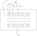
As shown in fig. 1 to 5, the present invention discloses a milling machine for door leaf processing, which comprises a machine base 1, a milling table 2, a fixing frame 3 and a milling mechanism 4, wherein the milling table 2 is fixed on the machine base 1, the fixing frame 3 is provided with a shifting mechanism 5, the shifting mechanism 5 is connected with the milling mechanism 4 and drives the milling mechanism 4 to horizontally move along the milling table 2, a plurality of chip removal ports 6 are arranged on the milling table 2 at intervals, the fixing frame 3 comprises a fixed vertical beam 31 and a fixed cross beam 32, the fixed vertical beam 31 is symmetrically fixed on the side walls of the two sides of the machine base 1, the fixed cross beam 32 is fixed on the fixed vertical beam 31, the fixed cross beam 32 is provided with a first installation groove 7 arranged towards the milling mechanism 4, the shifting mechanism 5 is positioned in the first installation groove 7, the shifting mechanism 5 comprises a lead screw 51, a top guide rail 52, a bottom guide rail 53, the top guide rail 52 and the bottom guide rail 53 are respectively fixed at the top and the bottom of the first mounting groove 7, the top guide rail 52 is vertically opposite to the bottom guide rail 53, the connecting block 54 is sleeved on the screw rod 51 and forms a threaded fit with the screw rod 51, the top and the bottom of the connecting block 54 are respectively provided with a top sliding opening and a bottom sliding opening, the top sliding opening is abutted against the top guide rail 52 and forms a sliding fit, the bottom sliding opening is abutted against the bottom guide rail 53 and forms a sliding fit, one side of the connecting block 54 facing the milling mechanism 4 is flush with the notch of the first mounting groove 7 and is fixed with the milling mechanism 4, so that the milling mechanism 4 is conveniently fixed on the side wall of the connecting block 54, the milling mechanism 4 is prevented from generating friction with the fixed cross beam 32 to cause inconvenient movement, when the milling mechanism 4 is used for processing a door leaf, generated chips can directly fall into the chip removal opening 6 and are discharged from, therefore, chips can be prevented from being accumulated on the milling table 2 to cause inconvenient processing, wherein one end of a screw 51 which is rotatably connected in the first mounting groove 7 can be externally connected with a motor and driven by the motor, when the screw 51 rotates, a connecting block 54 which is in threaded fit with the screw 51 can move on the screw 51 to drive a milling mechanism 4 which is connected with the connecting block 54 to horizontally move along the milling table 2, wherein the screw 51 has a small screw pitch, the minimum displacement of the connecting block 54 on the screw 51 is reduced due to the small screw pitch of the screw 51, so that the milling mechanism 4 has higher processing precision, and the connecting block 54 can respectively form sliding fit with a top guide rail 52 and a bottom guide rail 53 in the moving process, so that the connecting block 54 is more stable in the moving process, wherein the performance parameters of the top guide rail 52 and the bottom guide rail 53 are completely consistent, and the top guide rail 52 and the bottom guide rail 53 can respectively abut against the connecting block 54 to form limit fit, the connecting block 54 can be prevented from shaking in the moving process, so that the milling mechanism 4 is prevented from shaking in the process driven by the connecting block 54, the milling mechanism 4 is more stable in the machining process, and the machining precision is improved.
The fixed vertical beam 31 is provided with a second mounting groove 8 arranged towards the milling table 2, a chip blowing mechanism 9 is arranged in the second mounting groove 8, the chip blowing mechanism 9 comprises a rigid pipeline 91, a flexible pipeline 92 and an air nozzle 93, two ends of the rigid pipeline 91 are of a closed structure and are positioned in the second mounting groove 8, the rigid pipeline 91 is in clearance fit with the second mounting groove 8, the rigid pipeline 91 is provided with a plurality of air outlet ends 911 arranged at intervals, the air outlet end 911 is obliquely arranged towards the milling table 2, the air nozzle 93 is connected to the air outlet end 911, the rigid pipeline 91 is provided with an air inlet end 912, one end of the flexible pipeline 92 is communicated with the air inlet end 912, the other end of the flexible pipeline 92 is connected with an external air source, air can be automatically sent into the rigid pipeline 91 from the flexible pipeline 92 by starting the external air source, and is finally blown out from the air nozzle 93 communicated with the rigid pipeline 91, so that residual chips on the milling, discharge the piece from milling platform 2 through chip removal mouth 6, and then can further prevent that the piece from piling up and influencing processing on milling platform 2 to required intensity of labour when reducing the workman and removing the piece, wherein a plurality ofly just face the end 911 of giving vent to anger that milling platform 2 slope set up, make air cock 93 with give vent to anger can be with the more concentrated blowing of gas to milling platform 2 when end 911 is connected, thereby improve the blowing effect of blowing the piece mechanism 9 to the piece.
Still include twist grip 10, rigid conduit 91 both ends are rotated and are connected in second mounting groove 8, rigid conduit 91 one end is as extending the end, extend end downwardly extending to fixed perpendicular roof beam 31 outside with twist grip 10 fixed connection, be equipped with on the fixed perpendicular roof beam 31 around the regulation hole 11 of fixed perpendicular roof beam 31 lateral wall setting, flexible conduit 92 is connected with inlet end 912 through regulation hole 11, through rotatory twist grip 10, make the end 911 orientation of giving vent to anger in the rigid conduit 91 of rotating and connecting in second mounting groove 8 change, thereby can be with the air cock 93 of giving vent to anger end 911 UNICOM can be towards each corner of milling platform 2, and then the bits range of blowing bits mechanism 9 has been improved, further prevent that the piece from piling up on milling platform 2, wherein the regulation hole 11 of setting around fixed perpendicular roof beam 31 lateral wall, make when rigid conduit 91 rotates through regulation hole 11 let in second mounting groove 8 and with flexible conduit 92 that rigid conduit 91 inlet end 912 links to each other can prevent to produce with second mounting groove 8 The rigid pipe 91 cannot rotate due to dead jamming, so that the rotation range of the rigid pipe 91 is increased.
The collecting box 12 is arranged below the machine base 1, the collecting box 12 is vertically opposite to the chip removal port 6, and chips discharged through the chip removal port 6 on the milling table 2 can intensively fall into the collecting box 12, so that the chips are more conveniently treated, the chips are prevented from directly falling onto the ground to cause secondary pollution to the environment, and the labor intensity of workers for processing the chips is reduced.
The device also comprises a clamping mechanism 13, the clamping mechanism 13 comprises a locking piece 131, a connecting shaft 132, a connecting seat 133 and a clamping sleeve 134, two ends of the connecting shaft 132 are fixed on the side wall of the machine base 1 and are positioned below the chip removal port 6, the connecting seat 133 is symmetrically sleeved on the connecting shaft 132 and is in sliding connection with the connecting shaft 132, part of the connecting seat 133 is positioned on the chip removal port 6 and abuts against the front side wall and the rear side wall of the chip removal port 6 to form limiting fit, a clamping port 1341 is arranged on the clamping sleeve 134, the height of the clamping port 1341 is consistent with the thickness of a door leaf, part of the clamping sleeve 134 is positioned on the chip removal port 6 and abuts against the front side wall and the rear side wall of the chip removal port 6 to form limiting fit, the clamping sleeve 134 is locked on the side wall of the connecting seat 133 by the locking piece 131, the connecting seat 133 symmetrically sleeved on the connecting shaft 132 is moved, so that the connecting seat, thereby preventing the door leaf on the milling platform 2 from sliding during processing to influence the processing precision, and the connecting seat 133 part sleeved on the connecting shaft 132 is propped against the side wall of the chip removing opening 6 to form the limit fit, and the clamping sleeve 134 part locked on the connecting seat 133 is propped against the side wall of the chip removing opening 6 to form the limit fit, thereby preventing the deviation of the connecting seat 133 and the clamping sleeve 134 from affecting the clamping effect of the door leaf, wherein the height of the clamping opening 1341 on the clamping sleeve 134 needs to be consistent with the thickness of the door leaf, and the clamping sleeve 134 on the connecting seat 133 is locked through the locking piece 131, so that the removal and installation of the clamping sleeve 134 are more convenient, thereby being capable of more conveniently meeting the processing requirements of door leaves with different thicknesses by replacing the clamping sleeves 134 with different specifications, further improving the application range, the locking member 131 is preferably a manually-operable member to facilitate removal and installation of the retaining sleeve 134.
The use process of the invention is as follows:
placing a door leaf to be processed on a milling table 2, then pushing a connecting seat 133, enabling a clamping opening 1341 in a clamping sleeve 134 to be abutted against the door leaf for clamping, then starting a motor connected with a lead screw 51, enabling the lead screw 51 to start rotating, enabling a connecting block 54 which is sleeved on the lead screw 51 and forms threaded fit with the lead screw 51 to drive a milling mechanism 4 fixed on the connecting block 54 to move along the milling table 2, processing the door leaf, discharging chips generated by processing from the milling table 2 through a chip discharge opening 6 and dropping into a collecting box 12 below the milling table 2, after the processing is completed, starting an external air source, sending air into a rigid pipeline 91 through a flexible pipeline 92, finally blowing out the chips from an air nozzle 93 communicated with the rigid pipeline 91, blowing the chips remained on the milling table 2 into the chip discharge opening 6, and discharging the chips from the milling table 2 through the chip discharge opening 6, during the blowing process, the turning handle 10 can be manually rotated to adjust the orientation of the nozzle to blow towards every corner of the milling table 2, thereby further preventing the accumulation of debris on the milling table 2.
The present embodiment is only for explaining the present invention, and it is not limited to the present invention, and those skilled in the art can make modifications of the present embodiment without inventive contribution as needed after reading the present specification, but all of them are protected by patent law within the scope of the claims of the present invention.