CN211760170U - Milling machine convenient to it is clean - Google Patents
Milling machine convenient to it is clean Download PDFInfo
- Publication number
- CN211760170U CN211760170U CN202020148634.2U CN202020148634U CN211760170U CN 211760170 U CN211760170 U CN 211760170U CN 202020148634 U CN202020148634 U CN 202020148634U CN 211760170 U CN211760170 U CN 211760170U
- Authority
- CN
- China
- Prior art keywords
- milling machine
- fixedly connected
- workbench
- plate
- hose
- Prior art date
- Legal status (The legal status is an assumption and is not a legal conclusion. Google has not performed a legal analysis and makes no representation as to the accuracy of the status listed.)
- Expired - Fee Related
Links
Images

Abstract
The utility model discloses a milling machine convenient to it is clean belongs to milling machine technical field, and it includes milling machine equipment main part, the equal fixedly connected with fixed plate in top of the left and right sides face of milling machine equipment main part, the back fixed connection of rotating device and connecting plate is passed through to the positive top of fixed plate, the through-hole has been seted up in the front of fixed plate, the through-hole is located rotating device's below, be provided with the hose in the through-hole. This milling machine convenient to it is clean, through setting up the fixed plate, rotating device, the connecting plate, hose and shower nozzle, when clearing up the sweeps on the workstation, the liquid that utilizes the water pipe to carry is from the shower nozzle blowout, wash the sweeps to the row material inslot, the workman can rotate two connecting plates simultaneously, adjust the scope that a plurality of shower nozzle washed, make whole workstation can both be washed, avoid the sweeps to remain and cause the influence to follow-up processing on the workstation, the workman has reduced the workstation degree of difficulty of clearing up simultaneously.
Description
Technical Field
The utility model belongs to the technical field of the milling machine, specifically be a milling machine convenient to it is clean.
Background
The milling machine mainly refers to a machine tool for processing various surfaces of a workpiece by using a milling cutter. Typically the milling cutter is moved primarily in a rotary motion and the movement of the workpiece and the milling cutter is a feed motion. It can be used for processing plane, groove, various curved surfaces and gears.
When a workpiece is machined by the milling machine, a large amount of scraps can be produced, the accumulated scraps easily cause damage to the machine tool, the machine tool is serious in aging, the temperature of a cutting part is reduced by continuous liquid adding bodies in the machining process, the liquid and the scraps are mixed together and are very difficult to clean, the labor intensity of workers is greatly increased, and therefore the milling machine convenient to clean is needed.
SUMMERY OF THE UTILITY MODEL
Technical problem to be solved
In order to overcome the above-mentioned defect of prior art, the utility model provides a milling machine convenient to it is clean has solved the sweeps that current milling machine can produce at work, and the sweeps produces the influence to the lathe easily, and behind the sweeps mixed liquid, is difficult to the problem of clearance very much.
(II) technical scheme
In order to achieve the above object, the utility model provides a following technical scheme: the utility model provides a milling machine convenient to it is clean, includes milling machine equipment main part, the equal fixedly connected with fixed plate in top of milling machine equipment main part left and right sides face, the back fixed connection of rotating device and connecting plate is passed through to the positive top of fixed plate, the through-hole has been seted up in the front of fixed plate, the through-hole is located rotating device's below, be provided with the hose in the through-hole, the last fixed surface of hose connects the lower surface at the connecting plate, the position that the hose lower surface corresponds the connecting plate is provided with a plurality of shower nozzle.
The front of milling machine equipment main part is provided with the workstation, the workstation is located the below of two connecting plates, a plurality of dead slot has been seted up to the upper surface of workstation, equal fixedly connected with baffle all around on workstation surface, the left and right sides of workstation lower surface all is provided with row material tank, arrange the right side fixedly connected with collection box of material tank lower surface, the top at collection box front and back all is connected with the lower fixed surface of workstation through the gusset plate, the equal fixedly connected with dog of the left and right sides face of collection box inner wall, two the upper surface overlap joint of dog has the filter, the collection box lower surface is provided with drainage device.
As a further aspect of the present invention: the rotating device comprises a bearing, the back of the bearing is clamped above the front of the fixing plate, a rotating shaft is sleeved in the bearing, and one end of the front of the rotating shaft is fixedly connected to the back of the connecting plate.
As a further aspect of the present invention: the drainage device comprises a drainage pipe, the top end of the drainage pipe is communicated with the lower surface of the recovery box, and a valve is arranged inside the drainage pipe.
As a further aspect of the present invention: the upper surface fixedly connected with handle of filter, the surface of handle is provided with anti-skidding line.
As a further aspect of the present invention: the lower fixed surface of milling machine equipment main part is connected with the bottom plate, the lower fixed surface of bottom plate is connected with four supporting legs, four the supporting leg is located the four corners department of bottom plate lower surface respectively.
(III) advantageous effects
Compared with the prior art, the beneficial effects of the utility model reside in that:
1. this milling machine convenient to it is clean, through setting up the fixed plate, rotating device, the connecting plate, hose and shower nozzle, when clearing up the sweeps on the workstation, the liquid that utilizes the water pipe to carry is from the shower nozzle blowout, wash the sweeps to the row material inslot, the workman can rotate two connecting plates simultaneously, adjust the scope that a plurality of shower nozzle washed, make whole workstation can both be washed, avoid the sweeps to remain and cause the influence to follow-up processing on the workstation, the workman has reduced the workstation degree of difficulty of clearing up simultaneously.
2. This milling machine convenient to it is clean through setting up collection box, filter and drainage device, falls the collection box when the waste material from arranging the silo in, the filter can separate solid-liquid for liquid is discharged from drainage device department, thereby has realized solid-liquid separation, and the workman of being convenient for handles and retrieves the waste material.
3. This milling machine convenient to it is clean through setting up dead slot and baffle, has seted up the dead slot on the workstation, can make the sweeps fall the row material inslot under washing, and the baffle can block and wash in-process liquid and spatter the phenomenon all around, avoids milling machine equipment main part to be covered with water stain all around to the effect of protection milling machine equipment main part has been played.
Drawings
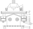
Fig. 1 is a schematic front view of a cross-sectional structure of the present invention;
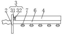
FIG. 2 is a schematic left-side view of the rotating device of the present invention;
FIG. 3 is a schematic structural view of the workbench of the present invention from above;
in the figure: 1 milling machine equipment body, 2 fixed plate, 3 rotating device, 31 bearing, 32 rotating shaft, 4 connecting plate, 5 through holes, 6 hose, 7 spray head, 8 workbench, 9 empty groove, 10 baffle, 11 discharge groove, 12 recovery box, 13 reinforcing plate, 14 baffle, 15 filter plate, 16 handle, 17 drainage device, 171 drain pipe, 172 valve, 18 bottom plate, 19 supporting leg.
Detailed Description
The technical solution of the present patent will be described in further detail with reference to the following embodiments.
As shown in fig. 1-3, the utility model provides a technical solution: a milling machine convenient to clean comprises a milling machine main body 1, a bottom plate 18 is fixedly connected to the lower surface of the milling machine main body 1, four supporting legs 19 are fixedly connected to the lower surface of the bottom plate 18, the four supporting legs 19 are respectively positioned at four corners of the lower surface of the bottom plate 18, the milling machine main body 1 can be more stable by arranging the bottom plate 18 and the supporting legs 19, and meanwhile, moisture on the ground is prevented from entering the inside of the milling machine main body 1, so that the milling machine main body 1 is protected, a fixing plate 2 is fixedly connected to the upper portions of the left side surface and the right side surface of the milling machine main body 1, the front upper portion of the fixing plate 2 is fixedly connected with the back of a connecting plate 4 through a rotating device 3, the rotating device 3 comprises a bearing 31, the back of the bearing 31 is clamped above the front portion of the fixing plate 2, a rotating shaft, through setting up rotating device 3, make connecting plate 4 can be stable fix on fixed plate 2, rotation that again can be nimble, through-hole 5 has been seted up in the front of fixed plate 2, through-hole 5 is located rotating device 3's below, be provided with hose 6 in the through-hole 5, the last fixed surface of hose 6 connects the lower surface at connecting plate 4, the position that hose 6 lower surface corresponds connecting plate 4 is provided with a plurality of shower nozzle 7, through setting up hose 6 and shower nozzle 7, utilize hose 6 transport liquid, make liquid from shower nozzle 7 blowout, can play the effect of flushing table 8.
The front side of the milling machine equipment main body 1 is provided with a workbench 8, the workbench 8 is positioned below the two connecting plates 4, the upper surface of the workbench 8 is provided with a plurality of empty grooves 9, the periphery of the surface of the workbench 8 is fixedly connected with baffle plates 10, the empty grooves 9 are arranged on the workbench 8 through the arrangement of the empty grooves 9 and the baffle plates 10, scraps can fall into a discharge groove 11 under washing, the baffle plates 10 can prevent the liquid splashing phenomenon in the washing process and avoid the water stain from being distributed around the milling machine equipment main body 1, so that the milling machine equipment main body 1 is protected, the left side and the right side of the lower surface of the workbench 8 are provided with discharge grooves 11, the right side of the lower surface of the discharge groove 11 is fixedly connected with a recovery box 12, the recovery box 12 is arranged, so that workers can conveniently collect and treat the scraps, thereby bringing convenience to the workers in treating the scraps, the upper sides of the front side and the back side of the recovery box 12 are fixedly connected with the lower surface of, the stability of the recycling bin 12 is further enhanced by arranging the reinforcing plate 13, the left side surface and the right side surface of the inner wall of the recycling bin 12 are fixedly connected with the check blocks 14, the filter plates 15 are lapped on the upper surfaces of the two check blocks 14, when waste falls into the recycling bin 12 by arranging the filter plates 15, the filter plates 15 can carry out solid-liquid separation on the waste, a worker can conveniently treat scraps, the upper surfaces of the filter plates 15 are fixedly connected with the handle 16, the surface of the handle 16 is provided with anti-slip lines, the handle 16 is arranged to facilitate the worker to take the filter plates 15 out of the recycling bin 12 for treating solid impurities by arranging the handle 16, the anti-slip lines on the surface of the handle 16 can play an anti-slip role, the lower surface of the recycling bin 12 is provided with the drainage device 17, the drainage device 17 comprises a drainage pipe 171, the top end of the drainage pipe 171 is communicated with the lower surface, by providing the drainage device 17, the worker controls the opening and closing of the valve 172, so that the worker can drain the liquid in the recovery tank 12 conveniently.
The utility model discloses a theory of operation does:
s1, when the multifunctional washing machine is used, a worker controls the water pump to supply liquid to the hose 6 through the external switch, the liquid is sprayed out of the plurality of nozzles 7 to wash scraps on the workbench 8, and in the process, the connecting plate 4 is rotated to drive the hose 6 and the plurality of nozzles 7 to rotate to wash different positions on the workbench 8;
s2, when the waste falls into the discharge groove 11 from the empty groove 9 on the workbench 8, the waste falls into the recovery box 12 along the inclined direction of the discharge groove 11, the filter plate 15 separates the solid and liquid in the waste, the worker discharges the liquid by controlling the opening and closing of the valve 172, and then the filter plate 15 is taken out by the handle 16 to collect the waste.
In the description of the present invention, it is to be noted that, unless otherwise explicitly specified or limited, the terms "mounted," "connected," and "connected" are to be construed broadly, and may be, for example, fixedly connected, detachably connected, or integrally connected; can be mechanically or electrically connected; they may be connected directly or indirectly through intervening media, or they may be interconnected between two elements. The specific meaning of the above terms in the present invention can be understood by those of ordinary skill in the art through specific situations.
Although the preferred embodiments of the present patent have been described in detail, the present patent is not limited to the above embodiments, and various changes can be made without departing from the spirit of the present patent within the knowledge of those skilled in the art.
Claims (5)
1. A milling machine convenient to it is clean, includes milling machine equipment main part (1), its characterized in that: the milling machine equipment comprises a milling machine main body (1), wherein fixing plates (2) are fixedly connected to the upper portions of the left side surface and the right side surface of the milling machine main body (1), the front upper portion of each fixing plate (2) is fixedly connected with the back surface of a connecting plate (4) through a rotating device (3), a through hole (5) is formed in the front surface of each fixing plate (2), the through hole (5) is located below the rotating device (3), a hose (6) is arranged in each through hole (5), the upper surface of each hose (6) is fixedly connected to the lower surface of the corresponding connecting plate (4), and a plurality of spray heads (7) are arranged on the lower surface of each hose;
the front surface of the milling machine equipment main body (1) is provided with a workbench (8), the workbench (8) is positioned below the two connecting plates (4), a plurality of empty grooves (9) are arranged on the upper surface of the workbench (8), baffles (10) are fixedly connected around the surface of the workbench (8), the left side and the right side of the lower surface of the workbench (8) are respectively provided with a discharge groove (11), the right side of the lower surface of the discharge groove (11) is fixedly connected with a recovery box (12), the upper parts of the front surface and the back surface of the recovery box (12) are fixedly connected with the lower surface of the workbench (8) through reinforcing plates (13), the recycling bin is characterized in that the left side surface and the right side surface of the inner wall of the recycling bin (12) are fixedly connected with check blocks (14), two check blocks (14) are lapped on the upper surfaces of the check blocks (15), and a drainage device (17) is arranged on the lower surface of the recycling bin (12).
2. A milling machine facilitating cleaning according to claim 1, wherein: rotating device (3) include bearing (31), the back joint of bearing (31) is in the positive top of fixed plate (2), has cup jointed pivot (32) in bearing (31), the positive one end fixed connection of pivot (32) is at the back of connecting plate (4).
3. A milling machine facilitating cleaning according to claim 1, wherein: the drainage device (17) comprises a drainage pipe (171), the top end of the drainage pipe (171) is communicated with the lower surface of the recovery box (12), and a valve (172) is arranged inside the drainage pipe (171).
4. A milling machine facilitating cleaning according to claim 1, wherein: the upper surface of the filter plate (15) is fixedly connected with a handle (16), and anti-skid grains are arranged on the surface of the handle (16).
5. A milling machine facilitating cleaning according to claim 1, wherein: the lower fixed surface of milling machine equipment main part (1) is connected with bottom plate (18), the lower fixed surface of bottom plate (18) is connected with four supporting legs (19), four supporting leg (19) are located the four corners department of bottom plate (18) lower surface respectively.
Priority Applications (1)
| Application Number | Priority Date | Filing Date | Title |
|---|---|---|---|
| CN202020148634.2U CN211760170U (en) | 2020-02-01 | 2020-02-01 | Milling machine convenient to it is clean |
Applications Claiming Priority (1)
| Application Number | Priority Date | Filing Date | Title |
|---|---|---|---|
| CN202020148634.2U CN211760170U (en) | 2020-02-01 | 2020-02-01 | Milling machine convenient to it is clean |
Publications (1)
| Publication Number | Publication Date |
|---|---|
| CN211760170U true CN211760170U (en) | 2020-10-27 |
Family
ID=72904557
Family Applications (1)
| Application Number | Title | Priority Date | Filing Date |
|---|---|---|---|
| CN202020148634.2U Expired - Fee Related CN211760170U (en) | 2020-02-01 | 2020-02-01 | Milling machine convenient to it is clean |
Country Status (1)
| Country | Link |
|---|---|
| CN (1) | CN211760170U (en) |
Cited By (2)
| Publication number | Priority date | Publication date | Assignee | Title |
|---|---|---|---|---|
| CN113977339A (en) * | 2021-09-30 | 2022-01-28 | 江西华派光电科技有限公司 | Milling cutter belt cleaning device |
| CN114192858A (en) * | 2021-12-30 | 2022-03-18 | 东莞市宝科精密机械有限公司 | Vertical numerically controlled milling machine with stand column thermal inclination balance control |
-
2020
- 2020-02-01 CN CN202020148634.2U patent/CN211760170U/en not_active Expired - Fee Related
Cited By (4)
| Publication number | Priority date | Publication date | Assignee | Title |
|---|---|---|---|---|
| CN113977339A (en) * | 2021-09-30 | 2022-01-28 | 江西华派光电科技有限公司 | Milling cutter belt cleaning device |
| CN113977339B (en) * | 2021-09-30 | 2023-02-28 | 江西华派光电科技有限公司 | Milling cutter belt cleaning device |
| CN114192858A (en) * | 2021-12-30 | 2022-03-18 | 东莞市宝科精密机械有限公司 | Vertical numerically controlled milling machine with stand column thermal inclination balance control |
| CN114192858B (en) * | 2021-12-30 | 2022-12-06 | 东莞市宝科精密机械有限公司 | Vertical numerically controlled milling machine with stand column thermal inclination balance control |
Similar Documents
| Publication | Publication Date | Title |
|---|---|---|
| CN211760170U (en) | Milling machine convenient to it is clean | |
| CN213888232U (en) | Drilling machine convenient to waste recycling | |
| CN210878846U (en) | Cutting machine convenient to clearance iron fillings | |
| CN113523891A (en) | Double-column plane milling machine convenient for collecting scraps | |
| CN210632959U (en) | Drilling equipment convenient to press from both sides tight panel | |
| CN112775461A (en) | Drilling equipment is used in processing of general machine part | |
| CN209599403U (en) | A kind of small-sized plank drilling machine | |
| CN216461763U (en) | Novel numerical control lathe | |
| JP2002126969A (en) | Machine tool | |
| CN213917290U (en) | Filtering device for high-speed numerical control engraving and milling machine | |
| CN213382316U (en) | Manhole cement product cutting device | |
| CN216138188U (en) | Full-automatic numerical control gantry milling machine with intelligent cleaning function for precision machining | |
| CN220825710U (en) | Milling machine with waste material clearing device | |
| CN205571921U (en) | A workstation for machining center | |
| CN214922706U (en) | Numerical control machine tool convenient to clean | |
| CN211136490U (en) | Novel smear metal is washed for machining device | |
| CN112109186B (en) | Multifunctional ceramic tea set manufacturing equipment | |
| CN214869608U (en) | Adjustable polishing lathe | |
| CN217570970U (en) | Drilling device with chip cleaning function for machining numerical control turning workpieces | |
| CN214767333U (en) | Milling cutter belt cleaning device | |
| CN214922249U (en) | Fixing base for installing gantry machining center | |
| CN218533726U (en) | Wheel inner hole machining numerical control vertical lathe without tool changing | |
| CN214920791U (en) | Milling machine is used in product processing that precision is high | |
| CN213318951U (en) | Waste collecting equipment for steel plate linear cutting machining | |
| CN216576874U (en) | Auxiliary device for numerical control machining center machine tool |
Legal Events
| Date | Code | Title | Description |
|---|---|---|---|
| GR01 | Patent grant | ||
| GR01 | Patent grant | ||
| CF01 | Termination of patent right due to non-payment of annual fee | ||
| CF01 | Termination of patent right due to non-payment of annual fee |
Granted publication date: 20201027 Termination date: 20210201 |