CN112815552B - Solar energy spotlight collection system convenient to installation - Google Patents
Solar energy spotlight collection system convenient to installation Download PDFInfo
- Publication number
- CN112815552B CN112815552B CN202110061987.8A CN202110061987A CN112815552B CN 112815552 B CN112815552 B CN 112815552B CN 202110061987 A CN202110061987 A CN 202110061987A CN 112815552 B CN112815552 B CN 112815552B
- Authority
- CN
- China
- Prior art keywords
- mounting
- installation
- hole
- groove
- solar energy
- Prior art date
- Legal status (The legal status is an assumption and is not a legal conclusion. Google has not performed a legal analysis and makes no representation as to the accuracy of the status listed.)
- Active
Links
Images


Classifications
-
- F—MECHANICAL ENGINEERING; LIGHTING; HEATING; WEAPONS; BLASTING
- F24—HEATING; RANGES; VENTILATING
- F24S—SOLAR HEAT COLLECTORS; SOLAR HEAT SYSTEMS
- F24S30/00—Arrangements for moving or orienting solar heat collector modules
- F24S30/40—Arrangements for moving or orienting solar heat collector modules for rotary movement
- F24S30/42—Arrangements for moving or orienting solar heat collector modules for rotary movement with only one rotation axis
- F24S30/425—Horizontal axis
-
- F—MECHANICAL ENGINEERING; LIGHTING; HEATING; WEAPONS; BLASTING
- F24—HEATING; RANGES; VENTILATING
- F24S—SOLAR HEAT COLLECTORS; SOLAR HEAT SYSTEMS
- F24S25/00—Arrangement of stationary mountings or supports for solar heat collector modules
- F24S25/60—Fixation means, e.g. fasteners, specially adapted for supporting solar heat collector modules
-
- Y—GENERAL TAGGING OF NEW TECHNOLOGICAL DEVELOPMENTS; GENERAL TAGGING OF CROSS-SECTIONAL TECHNOLOGIES SPANNING OVER SEVERAL SECTIONS OF THE IPC; TECHNICAL SUBJECTS COVERED BY FORMER USPC CROSS-REFERENCE ART COLLECTIONS [XRACs] AND DIGESTS
- Y02—TECHNOLOGIES OR APPLICATIONS FOR MITIGATION OR ADAPTATION AGAINST CLIMATE CHANGE
- Y02E—REDUCTION OF GREENHOUSE GAS [GHG] EMISSIONS, RELATED TO ENERGY GENERATION, TRANSMISSION OR DISTRIBUTION
- Y02E10/00—Energy generation through renewable energy sources
- Y02E10/40—Solar thermal energy, e.g. solar towers
- Y02E10/47—Mountings or tracking
Landscapes
- Engineering & Computer Science (AREA)
- Physics & Mathematics (AREA)
- Life Sciences & Earth Sciences (AREA)
- Sustainable Development (AREA)
- Sustainable Energy (AREA)
- Thermal Sciences (AREA)
- Chemical & Material Sciences (AREA)
- Combustion & Propulsion (AREA)
- Mechanical Engineering (AREA)
- General Engineering & Computer Science (AREA)
- Photovoltaic Devices (AREA)
Abstract
The invention discloses a solar condensation collecting device convenient to install, which comprises a base, a first supporting column, a second supporting column, an installation part, an installation plate and a solar collecting device body, wherein the first supporting column and the second supporting column are respectively connected with the base and the installation part through locking mechanisms, and automatic direction adjusting devices are arranged at the upper end and the lower end of the installation plate. The solar energy collecting device body is inclined towards the direction in which the heat absorption plate absorbs more heat, so that the solar energy collecting device body faces the irradiation direction of sunlight, the absorption efficiency of the solar energy collecting device body is improved, and the utilization rate of solar energy is improved.
Description
Technical Field
The invention relates to the technical field of solar components, in particular to a solar condensation collecting device convenient to install.
Background
Under the condition that fossil fuels are gradually reduced, solar energy becomes an important component of energy used by human beings as an environment-friendly pollution-free clean energy, and is continuously developed, the utilization of the solar energy is in a photo-thermal conversion mode and a photoelectric conversion mode, the solar power generation is a new renewable energy, and more solar power generation devices are available in the market. The solar module is formed by combining solar cells or solar cells of different specifications cut by a laser cutting machine or a steel wire cutting machine, and because the current and the voltage of single solar cells are very small, the single solar cells are firstly connected in series to obtain high voltage, then connected in parallel to obtain high current, then output through a diode, and packaged on a stainless steel, aluminum or other non-metal frame, glass on the upper surface and a back plate on the back surface are mounted, nitrogen is filled, and the solar module is integrally called as a module, namely a photovoltaic module or a solar cell module.
The existing solar light gathering acquisition device mostly detaches and transports a base, a support and a solar energy acquisition device body in order to facilitate transportation, and then is assembled by means of a wrench, a screw and a bolt, so that the solar energy acquisition device is inconvenient to mount and dismount, time-consuming, labor-consuming and inconvenient for people to use.
Disclosure of Invention
The invention aims to provide a solar energy condensation and collection device convenient to install so as to solve the problems in the background technology.
In order to solve the technical problems, the invention provides the following technical scheme: the utility model provides a solar energy spotlight collection system convenient to installation, includes base, first support column, second support column, installed part, mounting panel and solar energy collection system body, first support column and second support column all are connected with base and installed part respectively through locking mechanical system, the upper and lower both ends of mounting panel all are provided with the automatic device of transferring to.
In a preferred embodiment, the locking mechanism comprises a first mounting block fixedly arranged at the bottom ends of the first support column and the second support column and a first mounting groove fixedly arranged at the top end of the second support column, the two sides of the upper end of the base are respectively provided with a second mounting groove matched with the first mounting block, the side walls of the left end and the right end of the base are respectively provided with a mounting hole, one end of each mounting hole is communicated with the second mounting groove, a bolt is arranged at the position of each mounting hole, a first through hole is arranged on each bolt, a fixing bolt is arranged at the position of each first through hole, a fan-shaped gasket is fixedly arranged at the upper end of each fixing bolt, a second through hole is arranged on each first mounting block in a penetrating manner, a mounting groove is arranged at the top end of the inner side of each second through hole, a compression spring is fixedly arranged in the mounting groove, and a fan-shaped cam is fixedly arranged at the bottom end of the compression spring, the top end of the sector cam is fixedly provided with a connecting rod, the top end of the connecting rod passes through the side wall of the first mounting block, and are arranged inside the first supporting column and the second supporting column, the two sides of the top end of the first mounting block are both fixedly provided with supporting rods, a first rack is fixedly arranged at the upper end of the supporting rod, a gear is meshed with one side of the first rack, the upper end of the gear is engaged and connected with a second rack, one side of the second rack far away from the first rack is fixedly provided with a limiting block, one end of the limiting block penetrates through the side walls of the first supporting column and the second supporting column to be communicated with the first mounting groove, the bottom end of the mounting piece is fixedly provided with a second mounting block, the outer side wall of the second mounting block is provided with a limiting groove, the upper end of installed part has the connecting seat through activity round pin hub connection, the one end setting at the mounting panel of installed part is kept away from to the connecting seat.
In a preferred embodiment, the automatic direction regulating device comprises lifting rods arranged on the upper side and the lower side of the bottom end of the solar energy collecting device body and a heat absorbing plate arranged on the upper surface of the mounting plate, a liquid storage cavity is formed in the inner side, located on the heat absorbing plate, of the mounting plate, a movable plug is arranged inside the liquid storage cavity, mercury solution is filled in one side, located on the movable plug, of the liquid storage cavity, the movable rod and a reset spring are fixedly arranged on one side of the movable plug, balls are arranged at the upper end, located on one side, away from the movable plug, of the movable rod, an arc-shaped supporting plate is arranged at one end, away from the mercury solution, of the liquid storage cavity, a rolling groove is formed in the bottom end of the arc-shaped supporting plate, the lifting rods are fixedly arranged at the upper end of the arc-shaped supporting plate, the side wall of the mounting plate is penetrated through the top ends of the lifting rods, and the bottom end of the solar energy collecting device body is arranged.
In a preferred embodiment, a supporting gasket is fixedly arranged on one side of the upper surface of the base, which is located on the second mounting groove, the thickness of the supporting gasket is the same as that of the fan-shaped gasket, and anti-slip pads are arranged on the upper surfaces of the supporting gasket and the fan-shaped gasket.
In a preferred embodiment, the first mounting block is matched with the second mounting groove, the first mounting groove is matched with the second mounting block, the mounting hole and the second through hole are matched with the bolt, and the first through hole is matched with the fixing bolt.
In a preferred embodiment, the mounting part at the upper end of the second supporting column comprises a telescopic sleeve and a telescopic piece, the telescopic piece is arranged inside the telescopic sleeve in a sliding mode, and a fastening bolt is arranged on one side of the upper end of the telescopic sleeve.
In a preferred embodiment, the bottom end of the sector cam is arranged at the second through hole, and the connecting rod is slidably arranged inside the first mounting block, the first supporting column and the second supporting column.
In a preferred embodiment, the outer side walls of the bolt, the first mounting block and the second mounting block are all fixedly provided with a convex block, the inner side walls of the mounting hole, the first mounting groove and the second mounting groove are all provided with a groove, and the convex block is slidably arranged in the groove.
In a preferred embodiment, the heat absorbing plate is a black heat absorbing plate, and four liquid storage cavities in the mounting plate are arranged at four corners of the mounting plate.
In a preferred embodiment, the joint of the lifting rod and the side wall of the mounting plate is provided with a rubber sealing ring, and the ball is arranged in the rolling groove in a rolling mode.
Compared with the prior art, the invention has the following beneficial effects:
1. the invention is provided with a locking mechanism, when in installation, a first mounting block at the bottom ends of a first supporting column and a second supporting column is placed in a second mounting groove on a base, a second mounting block at the bottom end of a mounting piece is placed in the first mounting groove, a bolt is inserted into a mounting hole and a second through hole on the first mounting block, the bolt extrudes a sector cam in the second through hole, the sector cam is extruded and contracted into the mounting groove, so that the sector cam drives a connecting rod and a supporting rod to move upwards, the supporting rod can drive a first rack to move upwards, a gear rotates to drive a second rack to move, a limiting block can be pushed into a limiting groove on the side wall of the second mounting block when the second rack moves, the fixed installation of the supporting column and the mounting piece is realized, then a fixing bolt is inserted into the first through hole on the bolt to fix a pin, and the first supporting column and the second supporting column are used to compress a sector gasket on the fixing bolt, the fixing bolt, the first mounting block, the second mounting block, the support column and the mounting piece are fixed, the structure is simple, the mounting is carried out without a screwdriver or a spanner, the operation is convenient, and the use of people is convenient;
2. according to the invention, the automatic direction adjusting device is arranged, so that the solar energy collection device body has a better absorption effect when the solar energy collection device body absorbs the solar energy and is opposite to the sunlight, when the solar energy collection device body absorbs the solar energy, the heat absorption plates on the mounting plate can absorb different heat according to the irradiation angle of the sunlight, the heat absorption plates absorbing more heat have a better heating effect on the mercury solution in the liquid storage cavity, and the mercury solution absorbs heat and expands to enable the movable plug to drive the movable rod to move, so that the arc-shaped support rod drives the lifting rod to descend, the descending heights of the two ends of the solar energy collection device body are different, and the solar energy collection device body inclines towards the direction in which the heat absorption plates absorb more heat, so that the solar energy collection device body faces the irradiation direction of the sunlight, the absorption efficiency of the solar energy collection device body is improved, and the utilization rate of the solar energy is improved.
Drawings
The accompanying drawings, which are included to provide a further understanding of the invention and are incorporated in and constitute a part of this specification, illustrate embodiments of the invention and together with the description serve to explain the principles of the invention and not to limit the invention.
In the drawings:
FIG. 1 is a schematic view of the present invention after installation;
FIG. 2 is a schematic structural view of the present invention prior to installation;
FIG. 3 is an enlarged view of the structure at A in FIG. 1 according to the present invention;
FIG. 4 is an enlarged view of the structure at B in FIG. 1 according to the present invention;
FIG. 5 is a schematic structural view of the latch of the present invention;
FIG. 6 is a schematic top view of the mounting plate of the present invention;
FIG. 7 is a schematic view of the internal partial structure of the mounting plate of the present invention;
FIG. 8 is a schematic view of the construction of the arcuate support plate of the present invention;
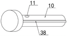
in the figure: 1, a base; 2 a first support column; 3 a second support column; 4, mounting a plate; 5, a solar energy collecting device body; 6 a first mounting block; 7 a first mounting groove; 8, a second mounting groove; 9, mounting holes; 10, a bolt; 11 a first through-hole; 12 fixing bolts; 13, a fan-shaped gasket; 14 a second via hole; 15, mounting a groove; 16 a compression spring; 17 a sector cam; 18 connecting rods; 19 a support rod; 20 a first rack; 21 a gear; 22 a second rack; 23, a limiting block; 24 a second mounting block; 25, limiting grooves; 26 movable pin shafts; 27 a connecting seat; 28 a lifter bar; 29 a heat absorbing plate; 30 liquid storage cavities; 31, a movable plug; 32 mercury solution; 33 a movable lever; 34 balls; 35 arc-shaped supporting plates; 36 rolling grooves; 37 supporting the spacer; 38 bumps; 39 a mounting member; 40 return spring.
Detailed Description
The technical solutions in the embodiments of the present invention will be clearly and completely described below with reference to the drawings in the embodiments of the present invention, and it is obvious that the described embodiments are only a part of the embodiments of the present invention, and not all of the embodiments. All other embodiments, which can be derived by a person skilled in the art from the embodiments given herein without making any creative effort, shall fall within the protection scope of the present invention.
Referring to fig. 1-8, the invention provides a solar energy light gathering device convenient to mount, which includes a base 1, a first support column 2, a second support column 3, a mounting member 39, a mounting plate 4 and a solar energy gathering device body 5, wherein the first support column 2 and the second support column 3 are respectively connected with the base 1 and the mounting member 39 through a locking mechanism, and the upper end and the lower end of the mounting plate 4 are respectively provided with an automatic direction adjusting device.
In a preferred embodiment, the locking mechanism comprises a first mounting block 6 fixedly arranged at the bottom of the first support column 2 and the second support column 3 and a first mounting groove 7 fixedly arranged at the top end of the second support column 3, two sides of the upper end of the base 1 are respectively provided with a second mounting groove 8 matched with the first mounting block 6, the side walls of the left and right ends of the base 1 are respectively provided with a mounting hole 9, one end of the mounting hole 9 is communicated with the second mounting groove 8, a bolt 10 is arranged at the mounting hole 9, a first through hole 11 is arranged on the bolt 10, a fixing bolt 12 is arranged at the first through hole 11, the upper end of the fixing bolt 12 is fixedly provided with a fan-shaped gasket 13, a second through hole 14 is arranged on the first mounting block 6 in a penetrating manner, a mounting groove 15 is arranged at the top end of the inner side of the second through hole 14, a compression spring 16 is fixedly arranged inside the mounting groove 15, the bottom end of the compression spring 16 is fixedly provided with a sector cam 17, the top end of the sector cam 17 is fixedly provided with a connecting rod 18, the top end of the connecting rod 18 penetrates through the side wall of the first mounting block 6 and is arranged inside the first supporting column 2 and the second supporting column 3, both sides of the top end of the first mounting block 6 are fixedly provided with supporting rods 19, the upper end of the supporting rod 19 is fixedly provided with a first rack 20, one side of the first rack 20 is meshed with a gear 21, the upper end of the gear 21 is meshed with a second rack 22, one side of the second rack 22 far away from the first rack 20 is fixedly provided with a limiting block 23, one end of the limiting block 23 penetrates through the side walls of the first supporting column 2 and the second supporting column 3 to be communicated with the first mounting groove 7, the bottom end of the mounting piece 39 is fixedly provided with a second mounting block 24, the outer side wall of the second mounting block 24 is provided with a limiting groove 25, the upper end of the mounting part 39 is connected with a connecting seat 27 through a movable pin shaft 26, and one end of the connecting seat 27 far away from the mounting part 39 is arranged at the bottom end of the mounting plate 4.
In a preferred embodiment, the automatic direction adjusting device comprises lifting rods 28 arranged at the upper side and the lower side of the bottom end of the solar energy collecting device body 5 and a heat absorbing plate 29 arranged on the upper surface of the mounting plate 4, a liquid storage cavity 30 is arranged inside the mounting plate 4 and positioned on the inner side of the heat absorbing plate 29, a movable plug 31 is arranged inside the liquid storage cavity 30, mercury solution 32 is filled in one side of the movable plug 31 inside the liquid storage cavity 30, a movable rod 33 and a return spring 40 are fixedly arranged on one side of the movable plug 31, a ball 34 is arranged at the upper end of one side of the movable rod 33 far away from the movable plug 31, an arc-shaped supporting plate 35 is arranged at one end of the liquid storage cavity 30 far away from the mercury solution 32, a rolling groove 36 is arranged at the bottom end of the arc-shaped supporting plate 35, the lifting rods 28 are fixedly arranged at the upper end of the arc-shaped supporting plate 35, and the top ends of the lifting rods 28 penetrate through the side wall of the mounting plate 4, and is arranged at the bottom end of the solar energy collecting device body 5.
In a preferred embodiment, a supporting gasket 37 is fixedly arranged on one side of the upper surface of the base 1, which is located on the second mounting groove 8, the thickness of the supporting gasket 37 is the same as that of the fan-shaped gasket 13, and anti-slip pads are arranged on the upper surfaces of the supporting gasket 37 and the fan-shaped gasket 13, the supporting gasket 37 and the fan-shaped gasket 13 can support the first supporting column 2 and the second supporting column 3, the anti-slip pads can make the first supporting column 2 and the second supporting column 3 more stable, and the fixing of the fixing bolt 12 can be realized when the first supporting column 2 and the second supporting column 3 compress the fan-shaped gasket 13.
In a preferred embodiment, the first mounting block 6 is matched with the second mounting groove 8, the first mounting groove 7 is matched with the second mounting block 24, the mounting hole 9 and the second through hole 14 are matched with the bolt 10, and the first through hole 11 is matched with the fixing bolt 12, so that the first support column 2, the second support column 3 and the mounting part 39 can be conveniently fixed.
In a preferred embodiment, the mounting part 39 at the upper end of the second supporting column 3 comprises a telescopic sleeve and a telescopic part, the telescopic part is slidably arranged inside the telescopic sleeve, a fastening bolt is arranged on one side of the upper end of the telescopic sleeve, so that the height of the lower end of the solar energy collecting device body 5 can be adjusted, and the inclination angle of the solar energy collecting device body 5 can be adjusted according to actual conditions.
In a preferred embodiment, the bottom end of the sector cam 17 is disposed at the second through hole 14, and the connecting rod 18 is slidably disposed inside the first mounting block 6 and the first and second supporting columns 2 and 3, so that the sector cam 17 and the connecting rod 18 can be conveniently driven to lift by the extrusion of the plug pin 10.
In a preferred embodiment, the outer side walls of the bolt 10, the first mounting block 6 and the second mounting block 24 are all fixedly provided with a projection 38, the inner side walls of the mounting hole 9, the first mounting groove 7 and the second mounting groove 8 are all provided with grooves, and the projection 38 is slidably arranged in the groove, so that the bolt 10, the first mounting block 6 and the second mounting block 24 can be conveniently positioned by the arrangement of the projection 38 and the groove.
In a preferred embodiment, the heat absorbing plate 29 is a black heat absorbing plate, and four liquid storage cavities 30 inside the mounting plate 4 are arranged at four corners of the mounting plate 4, so that the black heat absorbing plate has a good effect of absorbing sunlight.
In a preferred embodiment, a rubber seal is arranged at the joint of the lifting rod 28 and the side wall of the mounting plate 4, the ball 34 is arranged in the rolling groove 36 in a rolling manner, and the arrangement of the ball 34 and the rolling groove 36 facilitates the stability of the movement of the movable rod 33 when the movable plug 31 moves.
The working principle of the invention is as follows: when the fan-shaped cam is installed, the base 1 is fixed firstly, the first installation block 6 at the bottom ends of the first support column 2 and the second support column 3 is placed into the second installation groove 8 at the upper end of the base 1, the convex block 38 at the outer side of the first installation block 6 slides down along the groove at the side wall of the second installation groove 8 when the fan-shaped cam is placed into the fan-shaped cam, so that the second through hole 12 on the first installation block 6 corresponds to the installation hole 9, then the second installation block 24 at the bottom end of the installation piece 39 is placed into the first installation groove 7, the convex block 38 at the outer side of the second installation block 24 slides in along the groove at the inner side wall of the first installation groove 7, so that the limiting groove 25 at the outer side of the second installation block 24 corresponds to the limiting block 23, then the convex block 38 at the outer side of the plug pin 10 slides in along the groove at the inner side wall of the installation hole 9, so that the plug pin 10 penetrates through the installation hole 9 and is inserted into the second through hole 14 on the first installation block 6, the plug pin 10 impacts one side of the fan-shaped cam 17 after entering the second through hole 14, with the continuous extension of the bolt 10, the bolt 10 extrudes the sector cam 17, so that the sector cam 17 drives the connecting rod 18 to move upwards, the connecting rod 18 can drive the first rack 20 to move upwards through the supporting rod 19 when moving upwards, the first rack 20 can drive the gear 21 to rotate when moving, the gear 21 can drive the limiting block 23 to move towards the first mounting groove 7 when rotating, so that the limiting block 23 moves into the limiting groove 25 to fix the mounting part 39, after the bolt 10 penetrates through the second through hole 14, the first through hole 11 on the bolt 10 corresponds to the fixing bolt 12 on the base 1, the bolt 10 fixes the first mounting block 6, then the sector gasket 13 on the fixing bolt 12 is far away from the first supporting column 2 and the second supporting column 3, the fixing bolt 12 is inserted through the first through hole 11, the fixing bolt 12 is rotated after being inserted, the sector gasket 13 on the fixing bolt 12 is rotated below the first supporting column 2 and the second supporting column 3, the fan-shaped gasket 13 and the supporting gasket 37 are used for supporting the first supporting column 12 and the second supporting column 3, and the first supporting column 2 and the second supporting column 3 are used for compressing the fan-shaped gasket 13, so that the solar energy condensation collection device is mounted;
in the using process, the heat absorbing plate 29 on the upper surface of the mounting plate 4 can absorb sunlight to generate heat, the more sunlight, the better the heating effect is, the heat generated by the sunlight absorbed by the heat absorbing plate 29 can heat the mercury solution 32 in the liquid storage cavity 30, the mercury solution 32 is heated to expand to push the movable plug 31 to move, the movable plug 31 can drive the movable rod 33 to move when moving, the ball 34 can roll at the bottom end of the arc-shaped support plate 35 when moving the movable rod 33, the arc-shaped support plate 35 loses the limiting effect of the ball 34 and the movable rod 33 and then moves downwards under the action of gravity, so that the lifting rod 28 drives the solar energy collecting device body 5 to move downwards, the more heat absorbed by the heat absorbing plate 29 is, the more moving distances between the movable plug 31 and the movable rod 33 are increased, the more descending distances of the lifting rod 28 are increased, and the solar energy collecting device body 5 is inclined towards the heat absorbing plate 29 which absorbs more heat, the sunlight in the direction with more heat absorbed by the heat absorbing plate 29 is better, so that the solar energy collecting device body 5 has better sunlight absorbing effect, the mercury solution 32 does not expand after the heat absorbing plate 29 is cooled, the movable plug 31 returns to the initial position under the action of the return spring 40, and the solar energy collecting device body 5 also returns to the initial position.
It is noted that, herein, relational terms such as first and second, and the like may be used solely to distinguish one entity or action from another entity or action without necessarily requiring or implying any actual such relationship or order between such entities or actions. Also, the terms "comprises," "comprising," or any other variation thereof, are intended to cover a non-exclusive inclusion, such that a process, method, article, or apparatus that comprises a list of elements does not include only those elements but may include other elements not expressly listed or inherent to such process, method, article, or apparatus.
Finally, it should be noted that: although the present invention has been described in detail with reference to the foregoing embodiments, it will be apparent to those skilled in the art that changes may be made in the embodiments and/or equivalents thereof without departing from the spirit and scope of the invention. Any modification, equivalent replacement, or improvement made within the spirit and principle of the present invention should be included in the protection scope of the present invention.
Claims (9)
1. The utility model provides a solar energy spotlight collection system convenient to installation, includes base (1), first support column (2), second support column (3), installed part (39), mounting panel (4) and solar energy collection system body (5), its characterized in that: the first supporting column (2) and the second supporting column (3) are respectively connected with the base (1) and the mounting piece (39) through locking mechanisms, and automatic direction adjusting devices are arranged at the upper end and the lower end of the mounting plate (4);
the locking mechanism comprises a first installation block (6) fixedly arranged at the bottom ends of a first supporting column (2) and a second supporting column (3) and a first installation groove (7) fixedly arranged at the top end of the second supporting column (3), wherein second installation grooves (8) matched with the first installation block (6) are respectively arranged at two sides of the upper end of a base (1), installation holes (9) are respectively arranged on the side walls of the left end and the right end of the base (1), one end of each installation hole (9) is communicated with the corresponding second installation groove (8), a bolt (10) is arranged at each installation hole (9), a first through hole (11) is formed in each bolt (10), a fixed bolt (12) is arranged at each first through hole (11), a fan-shaped gasket (13) is fixedly arranged at the upper end of each fixed bolt (12), and a second through hole (14) is arranged on each first installation block (6) in a penetrating manner, the inner side top end of the second through hole (14) is provided with a mounting groove (15), a compression spring (16) is fixedly arranged inside the mounting groove (15), a sector cam (17) is fixedly arranged at the bottom end of the compression spring (16), a connecting rod (18) is fixedly arranged at the top end of the sector cam (17), the top end of the connecting rod (18) penetrates through the side wall of the first mounting block (6) and is arranged inside the first supporting column (2) and the second supporting column (3), supporting rods (19) are fixedly arranged on both sides of the top end of the first mounting block (6), a first rack (20) is fixedly arranged at the upper end of each supporting rod (19), a gear (21) is arranged on one side of the first rack (20) in a meshed manner, a second rack (22) is connected to the upper end of the gear (21), and a limiting block (23) is fixedly arranged on one side of the second rack (22) far away from the first rack (20), the lateral wall that the one end of stopper (23) passed first support column (2) and second support column (3) is linked together with first mounting groove (7), the bottom mounting of installed part (39) is provided with second installation piece (24), be provided with spacing groove (25) on the lateral wall of second installation piece (24), the upper end of installed part (39) is connected with connecting seat (27) through activity round pin axle (26), the one end setting that installed part (39) was kept away from in connecting seat (27) is in the bottom of mounting panel (4).
2. An easy to install solar concentrator collector apparatus according to claim 1, further comprising: the automatic direction adjusting device comprises lifting rods (28) arranged on the upper side and the lower side of the bottom end of a solar energy collecting device body (5) and a heat absorbing plate (29) arranged on the upper surface of a mounting plate (4), a liquid storage cavity (30) is arranged on the inner side, located on the heat absorbing plate (29), in the mounting plate (4), a movable plug (31) is arranged in the liquid storage cavity (30), mercury solution (32) is filled in one side, located on the movable plug (31), in the liquid storage cavity (30), a movable rod (33) and a reset spring (40) are fixedly arranged on one side of the movable plug (31), balls (34) are arranged at the upper end, far away from the movable plug (31), of the movable rod (33), an arc-shaped supporting plate (35) is arranged at one end, far away from the mercury solution (32), of the liquid storage cavity (30), and a rolling groove (36) is arranged at the bottom end of the arc-shaped supporting plate (35), the fixed lifter (28) that is provided with in upper end of arc backup pad (35), the lateral wall of mounting panel (4) is passed on the top of lifter (28) to the setting is in the bottom of solar energy collection device body (5).
3. An easy to install solar concentrator collector apparatus according to claim 1, further comprising: the upper surface of base (1) is located one side of second mounting groove (8) and all fixedly is provided with support gasket (37), the thickness of support gasket (37) is the same with the thickness of fan-shaped gasket (13), just the upper surface of support gasket (37) and fan-shaped gasket (13) all is provided with the slipmat.
4. An easy to install solar concentrator collector apparatus according to claim 1, further comprising: first installation piece (6) and second mounting groove (8) phase-match, first mounting groove (7) and second installation piece (24) phase-match, mounting hole (9) and second through-hole (14) all with bolt (10) phase-match, first through-hole (11) and gim peg (12) phase-match.
5. An easy to install solar concentrator collector apparatus according to claim 1, further comprising: installation part (39) of second support column (3) upper end include telescopic tube and extensible member, the extensible member slides and sets up inside telescopic tube, telescopic tube's upper end one side is provided with fastening bolt.
6. An easy to install solar concentrator collector apparatus according to claim 1, further comprising: the bottom of fan-shaped cam (17) sets up in second through-hole (14) department, connecting rod (18) slide to set up inside first installation piece (6) and first support column (2), second support column (3).
7. An easy to install solar concentrator collector apparatus according to claim 1, further comprising: the mounting structure is characterized in that a convex block (38) is fixedly arranged on the outer side wall of the bolt (10), the first mounting block (6) and the second mounting block (24), grooves are formed in the inner side wall of the mounting hole (9), the first mounting groove (7) and the second mounting groove (8), and the convex block (38) is slidably arranged in the grooves.
8. An easy-to-install solar concentrating collector apparatus according to claim 2 wherein: the heat absorbing plate (29) is a black heat absorbing plate, and four liquid storage cavities (30) in the mounting plate (4) are arranged and are respectively positioned at four corners of the mounting plate (4).
9. An easy to install solar concentrator collector apparatus according to claim 2, further comprising: the connecting part of the lifting rod (28) and the side wall of the mounting plate (4) is provided with a rubber sealing ring, and the ball (34) is arranged in the rolling groove (36) in a rolling way.
Priority Applications (1)
| Application Number | Priority Date | Filing Date | Title |
|---|---|---|---|
| CN202110061987.8A CN112815552B (en) | 2021-01-18 | 2021-01-18 | Solar energy spotlight collection system convenient to installation |
Applications Claiming Priority (1)
| Application Number | Priority Date | Filing Date | Title |
|---|---|---|---|
| CN202110061987.8A CN112815552B (en) | 2021-01-18 | 2021-01-18 | Solar energy spotlight collection system convenient to installation |
Publications (2)
| Publication Number | Publication Date |
|---|---|
| CN112815552A CN112815552A (en) | 2021-05-18 |
| CN112815552B true CN112815552B (en) | 2022-06-14 |
Family
ID=75869923
Family Applications (1)
| Application Number | Title | Priority Date | Filing Date |
|---|---|---|---|
| CN202110061987.8A Active CN112815552B (en) | 2021-01-18 | 2021-01-18 | Solar energy spotlight collection system convenient to installation |
Country Status (1)
| Country | Link |
|---|---|
| CN (1) | CN112815552B (en) |
Families Citing this family (1)
| Publication number | Priority date | Publication date | Assignee | Title |
|---|---|---|---|---|
| CN116938084A (en) * | 2023-07-06 | 2023-10-24 | 曾文彬 | Solar photovoltaic device with solar panel convenient to install |
Citations (8)
| Publication number | Priority date | Publication date | Assignee | Title |
|---|---|---|---|---|
| JP2005268671A (en) * | 2004-03-22 | 2005-09-29 | Hiji Denki:Kk | Tracking type solar panel operating apparatus |
| CN208015643U (en) * | 2018-02-27 | 2018-10-26 | 苏发照明工程集团有限公司 | A kind of solar components being easily installed |
| KR20190017080A (en) * | 2017-08-09 | 2019-02-20 | 유한회사 홍익산업 | Device for adjusting angle |
| CN209267512U (en) * | 2019-02-01 | 2019-08-16 | 河南耀业电力工程有限公司 | A kind of photovoltaic solar panel component |
| CN209588426U (en) * | 2019-01-25 | 2019-11-05 | 天津城建大学 | A kind of solar thermal collector being easily installed |
| CN111023593A (en) * | 2019-12-30 | 2020-04-17 | 扬州驿丰诚信息科技有限公司 | Solar energy component convenient to angle regulation and stable in installation |
| CN210745061U (en) * | 2019-10-10 | 2020-06-12 | 上海誉德动力技术集团股份有限公司 | A solar power panel with the function of cleaning dust |
| CN211239751U (en) * | 2019-10-16 | 2020-08-11 | 天津中汇能科技有限公司 | Adjustable solar photovoltaic bracket |
Family Cites Families (1)
| Publication number | Priority date | Publication date | Assignee | Title |
|---|---|---|---|---|
| US20120218652A1 (en) * | 2011-02-24 | 2012-08-30 | Peak Flux, Inc. | Optical concentrator systems, devices and methods |
-
2021
- 2021-01-18 CN CN202110061987.8A patent/CN112815552B/en active Active
Patent Citations (8)
| Publication number | Priority date | Publication date | Assignee | Title |
|---|---|---|---|---|
| JP2005268671A (en) * | 2004-03-22 | 2005-09-29 | Hiji Denki:Kk | Tracking type solar panel operating apparatus |
| KR20190017080A (en) * | 2017-08-09 | 2019-02-20 | 유한회사 홍익산업 | Device for adjusting angle |
| CN208015643U (en) * | 2018-02-27 | 2018-10-26 | 苏发照明工程集团有限公司 | A kind of solar components being easily installed |
| CN209588426U (en) * | 2019-01-25 | 2019-11-05 | 天津城建大学 | A kind of solar thermal collector being easily installed |
| CN209267512U (en) * | 2019-02-01 | 2019-08-16 | 河南耀业电力工程有限公司 | A kind of photovoltaic solar panel component |
| CN210745061U (en) * | 2019-10-10 | 2020-06-12 | 上海誉德动力技术集团股份有限公司 | A solar power panel with the function of cleaning dust |
| CN211239751U (en) * | 2019-10-16 | 2020-08-11 | 天津中汇能科技有限公司 | Adjustable solar photovoltaic bracket |
| CN111023593A (en) * | 2019-12-30 | 2020-04-17 | 扬州驿丰诚信息科技有限公司 | Solar energy component convenient to angle regulation and stable in installation |
Also Published As
| Publication number | Publication date |
|---|---|
| CN112815552A (en) | 2021-05-18 |
Similar Documents
| Publication | Publication Date | Title |
|---|---|---|
| CN112815552B (en) | Solar energy spotlight collection system convenient to installation | |
| CN213094118U (en) | Solar photovoltaic panel assembly | |
| CN219420704U (en) | Cleaning structure of photovoltaic board | |
| CN114900116B (en) | Support for solar power generation for tracking solar height | |
| CN221448331U (en) | Optical platform adjustment mechanism for support | |
| CN218217175U (en) | Stable structure of photovoltaic support | |
| CN218416259U (en) | Angle self-adjustment solar support | |
| CN110568863A (en) | A solar power generation device | |
| CN216356544U (en) | Battery plate splicing mechanism for photovoltaic power generation | |
| CN213521752U (en) | Adjustable support of Y type photovoltaic solar cell panel | |
| CN117559887A (en) | Foldable solar panel device | |
| CN211720508U (en) | Solar photovoltaic power generation device | |
| CN211630128U (en) | Novel solar photovoltaic thermal system | |
| CN108540055A (en) | A kind of solar panels Fast Installation structure | |
| CN223625800U (en) | New forms of energy photovoltaic board stabilizes installing support | |
| CN112787578B (en) | New energy power generation device | |
| CN216625668U (en) | A kind of adjustment device of solar power panel for photovoltaic power generation | |
| CN223652178U (en) | Solar cell module convenient to installation | |
| CN216565026U (en) | Solar heat collecting device | |
| CN214094972U (en) | Tube-plate type heat absorbing device for flat plate type heat collector | |
| CN221467620U (en) | High-strength cavity photovoltaic bracket | |
| CN221652511U (en) | Improved photovoltaic power station | |
| CN112491339A (en) | Movable photovoltaic power generation assembly and use method | |
| CN222915933U (en) | Movable device solar panel bracket | |
| CN220507293U (en) | High-efficiency solar heat collector |
Legal Events
| Date | Code | Title | Description |
|---|---|---|---|
| PB01 | Publication | ||
| PB01 | Publication | ||
| SE01 | Entry into force of request for substantive examination | ||
| SE01 | Entry into force of request for substantive examination | ||
| GR01 | Patent grant | ||
| GR01 | Patent grant |