CN112810883A - Material stripping device for coil material sponge and automatic equipment for applying film in shell - Google Patents
Material stripping device for coil material sponge and automatic equipment for applying film in shell Download PDFInfo
- Publication number
- CN112810883A CN112810883A CN202110133304.5A CN202110133304A CN112810883A CN 112810883 A CN112810883 A CN 112810883A CN 202110133304 A CN202110133304 A CN 202110133304A CN 112810883 A CN112810883 A CN 112810883A
- Authority
- CN
- China
- Prior art keywords
- film
- driving
- shell
- stripping
- assembly
- Prior art date
- Legal status (The legal status is an assumption and is not a legal conclusion. Google has not performed a legal analysis and makes no representation as to the accuracy of the status listed.)
- Granted
Links
- 239000000463 material Substances 0.000 title claims abstract description 131
- 238000007599 discharging Methods 0.000 claims abstract description 49
- 238000010030 laminating Methods 0.000 claims abstract description 25
- 230000007246 mechanism Effects 0.000 claims description 54
- 230000000712 assembly Effects 0.000 claims description 23
- 238000000429 assembly Methods 0.000 claims description 23
- 238000001514 detection method Methods 0.000 claims description 22
- 238000003825 pressing Methods 0.000 claims description 13
- 239000000969 carrier Substances 0.000 claims description 5
- 230000007306 turnover Effects 0.000 claims description 5
- 238000004519 manufacturing process Methods 0.000 abstract description 8
- 230000008901 benefit Effects 0.000 abstract description 3
- 230000002860 competitive effect Effects 0.000 abstract description 3
- 238000000034 method Methods 0.000 description 22
- 230000008569 process Effects 0.000 description 16
- 239000012528 membrane Substances 0.000 description 12
- 239000002699 waste material Substances 0.000 description 3
- 238000005516 engineering process Methods 0.000 description 2
- 238000012986 modification Methods 0.000 description 2
- 230000004048 modification Effects 0.000 description 2
- 230000009471 action Effects 0.000 description 1
- 230000009286 beneficial effect Effects 0.000 description 1
- 230000008859 change Effects 0.000 description 1
Images


Classifications
-
- B—PERFORMING OPERATIONS; TRANSPORTING
- B65—CONVEYING; PACKING; STORING; HANDLING THIN OR FILAMENTARY MATERIAL
- B65B—MACHINES, APPARATUS OR DEVICES FOR, OR METHODS OF, PACKAGING ARTICLES OR MATERIALS; UNPACKING
- B65B33/00—Packaging articles by applying removable, e.g. strippable, coatings
- B65B33/02—Packaging small articles, e.g. spare parts for machines or engines
-
- B—PERFORMING OPERATIONS; TRANSPORTING
- B65—CONVEYING; PACKING; STORING; HANDLING THIN OR FILAMENTARY MATERIAL
- B65B—MACHINES, APPARATUS OR DEVICES FOR, OR METHODS OF, PACKAGING ARTICLES OR MATERIALS; UNPACKING
- B65B41/00—Supplying or feeding container-forming sheets or wrapping material
- B65B41/02—Feeding sheets or wrapper blanks
- B65B41/10—Feeding sheets or wrapper blanks by rollers
-
- B—PERFORMING OPERATIONS; TRANSPORTING
- B65—CONVEYING; PACKING; STORING; HANDLING THIN OR FILAMENTARY MATERIAL
- B65B—MACHINES, APPARATUS OR DEVICES FOR, OR METHODS OF, PACKAGING ARTICLES OR MATERIALS; UNPACKING
- B65B57/00—Automatic control, checking, warning, or safety devices
- B65B57/02—Automatic control, checking, warning, or safety devices responsive to absence, presence, abnormal feed, or misplacement of binding or wrapping material, containers, or packages
- B65B57/04—Automatic control, checking, warning, or safety devices responsive to absence, presence, abnormal feed, or misplacement of binding or wrapping material, containers, or packages and operating to control, or to stop, the feed of such material, containers, or packages
Abstract
The invention discloses a stripping device for coil sponge, which comprises a first mounting frame, and a discharging roller, a passing rail, a stripping assembly, a pulling assembly and a receiving roller which are arranged on the first mounting frame, wherein the stripping assembly is positioned at the tail end of the passing rail, the discharging roller and the receiving roller are respectively positioned above and below the passing rail, and the pulling assembly is positioned below the passing rail. The automatic equipment for laminating the film in the shell comprises the peeling device, a machine table, a turntable, a discharging device, a moving device and a film laminating device, wherein the turntable, the discharging device, the moving device and the film laminating device are arranged on the end face of the machine table, and the film peeling device is also arranged on the machine table. The automatic equipment for sticking the film in the shell is unified, adjustable and controllable; the speed is high, and the efficiency is high; only the materials are replaced and the products are collected manually, and one person can operate a plurality of devices, so that the labor is saved, and the cost is reduced; automatic production, less personnel and easy management; low production cost and good product quality, greatly improves the market competitive advantage and is suitable for wide popularization and use.
Description
Technical Field
The invention relates to the field of automatic production technical equipment, in particular to a material stripping device for a coil material sponge and automatic equipment for sticking a film in a shell.
Background
The existing process for pasting sponge in the shell is completed manually. Manual stripping is performed, so that the efficiency is low; the manual workload is large, and the manual demand is high; can not adapt to the modern production.
Disclosure of Invention
According to one aspect of the invention, the stripping device for the coil material sponge comprises a first mounting frame, and a discharging roller, a passing rail, a stripping assembly, a pulling assembly and a receiving roller which are arranged on the first mounting frame, wherein the stripping assembly is positioned at the tail end of the passing rail, the discharging roller and the receiving roller are respectively positioned above and below the passing rail, and the pulling assembly is positioned below the passing rail; the material belt is output from the discharging roller and sequentially passes through the material passing rail, the material stripping assembly and the material pulling assembly to be input into the material receiving roller.
In the stripping device, the material belt is output from the discharging roller, and under the driving of the pulling assembly, after the material belt passes through the material passing rail, the film body on the material belt is stripped to the stripping platform, and finally the waste material belt is wound to the material receiving roller.
In some embodiments, the stripping assembly comprises a stripping platform, a material guide block and a mounting seat, the stripping platform and the material guide block are both arranged on the mounting seat, the material guide block is located below the stripping platform, and a material guide rod is arranged at the lower end of the material guide block.
Therefore, when the material belt passes through the stripping assembly, the material belt is input into the material guide block through the material passing track and is input into the material pulling assembly around the material guide rod below the material guide block, and the film body on the material belt is stripped to the end face of the stripping platform.
In some embodiments, the material pulling assembly includes a driving motor, a driving guide roller and a material pressing guide roller, the driving guide roller and the material pressing guide roller are disposed on the first mounting frame and distributed vertically, and the driving motor is disposed on the first mounting frame and drivingly connected to the driving guide roller.
Therefore, the material belt passes through the driving guide roller and the material pressing guide roller, and the driving motor drives the driving guide roller so as to pull the material belt.
In some embodiments, the first mounting frame further includes a sixth driving member, the swage guide roller is slidably disposed up and down, and the sixth driving member is disposed on the first mounting frame and is drivingly connected to the swage guide roller.
Therefore, the sixth driving piece driving pressing roller is matched with the driving guide roller to extrude the material belt, and the friction force of the material pulling is improved.
According to one aspect of the invention, the automatic equipment for sticking the film in the shell is further provided, and comprises the material stripping device, a machine table, a rotary table, a discharging device, a material moving device and a film sticking device, wherein the rotary table, the discharging device, the material moving device and the film sticking device are arranged on the end surface of the machine table;
the membrane stripping device is configured to provide a membrane body;
the film pasting device is configured to transfer the film body into the shell;
the material moving device is configured to move the transferred shell into the discharging device;
the discharging device is configured to discharge the transferred shell.
The invention provides automatic equipment for sticking a sponge in a shell. In the working process of the equipment, the shell is input from a supply carrier of one of the vacant positions, and the shell is sequentially input into the working ends of the film sticking device and the material moving device along with the rotation of the turntable; the film body is transferred and pasted into the shell by the film pasting device, and then the shell after film pasting is input into the material moving device; the material moving device inputs the finished product into the discharging device, and the discharging device inputs the finished product into the next procedure. The automatic transfer in the shell can be realized to this equipment, with the diaphragm body transfer to in the casing automatically. This equipment satisfies the technology demand, and easy operation is changed, improves the efficiency of producing, improves the yield of producing, reduces artifical working strength, reduces the manpower demand.
In some embodiments, the film sticking device comprises a multi-axis manipulator, a first CCD detection mechanism and a sticking mechanism, the sticking mechanism is arranged at the driving end of the multi-axis manipulator, the first CCD detection mechanism is arranged on the end face of the machine table, the sticking mechanism comprises a second mounting frame and a plurality of film suction components, the second mounting frame is arranged at the driving end of the multi-axis manipulator, and the plurality of film suction components are arrayed on the second mounting frame.
From this, the pad pasting in-process of pad pasting device, multiaxis manipulator drive pasting mechanism removes, waits that the pasting mechanism gets the diaphragm after to detect the position of diaphragm through first CCD detection mechanism, paste again in the casing at last.
In some embodiments, the material moving device includes a third mounting frame, a first driving module, a second driving element and a first clamping jaw, the first driving module is disposed on the third mounting frame and above the turntable, the second driving element is disposed at a driving end of the first driving module, and the first clamping jaw is disposed at a driving end of the second driving element.
From this, move among the material device, first drive module, the first clamping jaw of second driving piece drive move, and first clamping jaw snatchs the casing, moves the casing to discharging device in.
In some embodiments, the discharging device includes a conveying rail, a second CCD detecting mechanism and a rejecting mechanism, the conveying rail, the second CCD detecting mechanism and the rejecting mechanism are all fixed on the end surface of the machine platform, the working end of the second CCD detecting mechanism is located above the conveying rail, and the working end of the rejecting mechanism is located on one side of the conveying rail.
Therefore, the shell is placed in the conveying track to be conveyed, the second CCD detection mechanism carries out transfer detection on the shell in the conveying process, qualified products are input into the next procedure through the conveying track, and unqualified products are removed through the removing mechanism.
In some embodiments, the station carrier includes a mounting plate, a swing frame, a first spring and an elastic clamping assembly, the mounting plate is fixed on the end face of the turntable, a hinge groove is formed in the mounting plate, the swing frame is rotatably arranged in the hinge groove, a convex block is arranged at the lower end of the mounting plate and located on one side of the hinge groove, the first spring is hinged between the swing frame and the convex block, a limiting block is arranged at the lower end of the mounting plate and located at one end of the hinge groove, the limiting block is detachably matched with the swing frame, and the elastic clamping assembly is arranged on the upper end face of the swing frame.
From this, the casing is inserted on the elasticity clamping subassembly, and the elasticity clamping subassembly can swing on the mounting panel, simplifies work step.
In some embodiments, the in-shell film laminating automation equipment further comprises a turnover assembly and two opening and clamping assemblies, wherein the two opening and clamping assemblies are arranged on the end face of the machine table and respectively correspond to the feeding station and the discharging station, and the opening and clamping assemblies are matched with the elastic clamping assemblies; the overturning assembly is arranged on the end face of the machine table, corresponds to the film pasting station and is matched with the swing frame.
From this, open through opening the clamp subassembly and press from both sides the processing to the elasticity clamping subassembly, through upset subassembly to the handling of overturning of swing span.
The invention has the following beneficial effects: the automatic equipment for sticking the film in the shell is unified, adjustable and controllable; the speed is high, and the efficiency is high; only the materials are replaced and the products are collected manually, and one person can operate a plurality of devices, so that the labor is saved, and the cost is reduced; automatic production, less personnel and easy management; low production cost and good product quality, greatly improves the market competitive advantage and is suitable for wide popularization and use.
Drawings
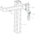
Fig. 1 is a schematic perspective view of an in-housing film laminating automation apparatus according to an embodiment of the present invention.
Fig. 2 is a schematic top view of the automated in-housing film laminating apparatus shown in fig. 1.
Fig. 3 is a schematic perspective view of a film peeling device in the automated in-shell film sticking apparatus shown in fig. 1.
Fig. 4 is a schematic perspective view of a film sticking device in the in-shell film sticking automation apparatus shown in fig. 1.
Fig. 5 is an enlarged schematic view of a portion of fig. 3.
Fig. 6 is a schematic perspective view of a material moving device in the in-shell film sticking automation equipment shown in fig. 1.
Fig. 7 is a schematic perspective view of a discharging device in the automatic in-shell film laminating apparatus shown in fig. 1.
Fig. 8 is a schematic perspective view of a rotary disk portion of the in-housing film-laminating automation apparatus shown in fig. 1.
Fig. 9 is a schematic perspective view of the feeding and discharging station part of the turntable shown in fig. 8.
Fig. 10 is a schematic perspective view of a film laminating station portion of the turntable shown in fig. 8.
Fig. 11 is a schematic perspective view of a material tape in the film stripping device shown in fig. 3.
Fig. 12 is a schematic perspective view of a half-section state of a finished product produced in the in-shell film-sticking automation apparatus shown in fig. 1.
Reference numbers in the figures: 0-machine table, 1-rotary table, 2-discharging device, 21-conveying track, 22-second CCD detection mechanism, 23-removing mechanism, 231-second driving module, 231-third driving piece, 233-second clamping jaw, 3-material moving device, 31-third mounting frame, 32-first driving module, 33-second driving piece, 34-first clamping jaw, 4-film removing device, 41-first mounting frame, 42-discharging roller, 43-material passing track, 44-material removing component, 441-material removing platform, 442-material guiding block, 443-mounting seat, 444-guide rod, 45-material pulling component, 451-driving motor, 452-driving guide roller, 453-material pressing guide roller, 454-sixth driving piece, 46-material receiving roller, 5-multi-shaft film sticking device, 51-mechanical arm, 52-first CCD detection mechanism, 53-material sticking mechanism 531, second mounting frame, 532-several material sucking components, 5321-first driving piece, 5322-sliding plate, 5323-sucking disc, 6-station carrier, 61-mounting plate, 611-hinge groove, 612-lug, 613-limiting block, 62-swing frame, 63-first spring, 64-elastic clamping assembly, 641-station block, 6411-station groove, 642-clamping plate, 643-sliding block, 644-first pulley, 645-second spring, 65-second pulley, 7-opening clamping assembly, 71-fourth driving piece, 72-pushing block, 8-overturning assembly, 81-fifth driving piece, 82-pushing block, a-shell, b-membrane body and c-material belt.
Detailed Description
The present invention will be described in further detail with reference to the accompanying drawings.
Fig. 1-2 schematically show an in-shell film-laminating automation device according to an embodiment of the present invention, which includes a machine table 0, and a turntable 1, a discharging device 2, a material moving device 3, a film peeling device 4, and a film laminating device 5 disposed on an end surface of the machine table 0, wherein the material moving device 3 and the film laminating device 5 are disposed at an edge position of the turntable 1 and are adjacently distributed, the film peeling device 4 is disposed at one side of the film laminating device 5, the discharging device 2 is disposed at one side of the material moving device 3, a plurality of station carriers 6 are circumferentially arrayed at an outer edge of the end surface of the turntable 1, a housing a is input into one of the station carriers 6 and moves to a working end of the film laminating device 5 and the material moving device 3 along with the turntable 1,
the peeling device 4 is configured to provide a film body b;
the film sticking device 5 is configured to transfer the film body b into the shell a;
the material moving device 3 is configured to move the transferred shell a into the discharging device 2;
the discharging device 2 is configured to discharge the transferred housing a.
The invention provides automatic equipment for sticking a sponge in a shell. In the working process of the equipment, a shell a is input from a supply carrier of one vacancy, and the shell a is sequentially input into the working ends of the film sticking device 5 and the material moving device 3 along with the rotation of the turntable 1; the film body b is transferred and pasted into the shell a by the film pasting device 5, and then the shell a after film pasting is input into the material moving device 3; the material moving device 3 inputs the finished product into the discharging device 2, and the discharging device 2 inputs the finished product into the next working procedure. The automatic transfer in the shell can be realized by the equipment, and the membrane body b is automatically transferred and pasted to the shell body a. This equipment satisfies the technology demand, and easy operation is changed, improves the efficiency of producing, improves the yield of producing, reduces artifical working strength, reduces the manpower demand.
With reference to fig. 3 and 11, the stripping device for the coil material sponge includes a first mounting frame 41, and a discharge roller 42, a material passing rail 43, a stripping assembly 44, a material pulling assembly 45, and a material receiving roller 46 which are arranged on the first mounting frame 41, wherein the stripping assembly 44 is located at the tail end of the material passing rail 43, the discharge roller 42 and the material receiving roller 46 are respectively located above and below the material passing rail 43, and the material pulling assembly 45 is located below the material passing rail 43; the material belt c is output from the discharging roller 42 and sequentially passes through the material passing rail 43, the material stripping assembly 44 and the material pulling assembly 45 to be input into the material receiving roller 46.
In the stripping device, a material belt c is output from a discharge roller 42, and under the driving of a material pulling assembly 45, after the material belt c passes through a material passing rail 43, a film body b on the material belt c is stripped to a stripping platform 441, and finally the waste material belt c is wound into a material receiving roller 46.
Referring to fig. 3, the stripping assembly 44 includes a stripping platform 441, a guide block 442, and a mounting base 443, wherein the stripping platform 441 and the guide block 442 are both disposed on the mounting base 443, the guide block 442 is located below the stripping platform 441, and a guide rod is disposed at a lower end of the guide block 442. When the material tape c passes through the stripping assembly 44, the material tape c is fed into the material guide block 442 via the material rail 43 and is fed into the material pulling assembly 45 around the material guide rod below the material guide block 442, and the film b on the material tape c is peeled off to the end surface of the stripping platform 441.
Referring to fig. 3, the drawing assembly 45 includes a driving motor 451, a driving guide roller 452, and a pressing guide roller 453, wherein the driving guide roller 452 and the pressing guide roller 453 are disposed on the first mounting frame 41 and distributed vertically, the driving motor 451 is disposed on the first mounting frame 41 and drivingly connected to the driving guide roller 452, the material belt c passes between the driving guide roller 452 and the pressing guide roller 453, and the driving motor 451 drives the driving guide roller 452, so as to draw the material belt c.
With reference to fig. 3, the first mounting frame 41 further includes a sixth driving element 454, the pressing guide roller 453 is disposed to slide up and down, and the sixth driving element 454 is disposed on the first mounting frame 41 and is drivingly connected to the pressing guide roller 453. The sixth driving element 454 drives the material pressing roller to cooperate with the driving guide roller 452 to extrude the material belt c, so as to increase the friction force of the material pulling.
With reference to fig. 4-5, the film pasting device 5 includes a multi-axis manipulator 51, a first CCD detection mechanism 52 and a pasting mechanism 53, the pasting mechanism 53 is disposed at a driving end of the multi-axis manipulator 51, the first CCD detection mechanism 52 is disposed on an end surface of the machine platform 0, the pasting mechanism 53 includes a second mounting bracket 531 and a plurality of film sucking assemblies 532, the second mounting bracket 531 is disposed at the driving end of the multi-axis manipulator 51, and the plurality of film sucking assemblies 532 are arrayed on the second mounting bracket 531. In the embodiment, the number of the membrane suction assemblies is four, the four membrane suction assemblies are distributed in an array manner, the four membrane suction assemblies work independently, and the four membrane suction assemblies can take four membrane materials at a time.
In the film sticking process of the film sticking device 5, the multi-axis manipulator 51 drives the sticking mechanism 53 to move, and after the sticking mechanism 53 takes the film body b, the position of the film body b is detected through the first CCD detection mechanism 52 and finally stuck to the shell a.
With reference to fig. 4-5, the membrane sucking assembly includes a first driving member 5321, a sliding plate 5322 and a sucking disc 5323, the first driving member 5321 is disposed at an upper end of the second mounting frame 531, the sliding plate 5322 is movably disposed at a lower end of the second mounting frame 531, the first driving member 5321 is drivingly connected to the sliding plate 5322, and the sucking disc 5323 is disposed at an end of the sliding plate 5322 far from the first driving member 5321.
In the membrane suction assembly, the first driving member 5321 can drive the sliding plate 5322 to move back and forth, so as to drive the suction cup 5323 to move back and forth, and thus the membrane body b is inserted into the shell a for rotary attachment.
Referring to fig. 6, the material moving device 3 includes a third mounting frame 31, a first driving module 32, a second driving member 33 and a first clamping jaw 34, the first driving module 32 is disposed on the third mounting frame 31 and located above the turntable 1, the second driving member 33 is disposed at the driving end of the first driving module 32, and the first clamping jaw 34 is disposed at the driving end of the second driving member 33.
In the material moving device 3, the first driving module 32 and the second driving member 33 drive the first clamping jaw 34 to move, and the first clamping jaw 34 grabs the shell a and moves the shell a to the discharging device 2.
With reference to fig. 7, the discharging device 2 includes a conveying rail 21, a second CCD detecting mechanism 22 and a rejecting mechanism 23, the conveying rail 21, the second CCD detecting mechanism 22 and the rejecting mechanism 23 are all fixed on the end surface of the machine table 0, the working end of the second CCD detecting mechanism 22 is located above the conveying rail 21, and the working end of the rejecting mechanism 23 is located on one side of the conveying rail 21. The shell a is placed in the conveying track 21 for conveying, the second CCD detection mechanism 22 carries out transfer detection on the shell a in the conveying process, qualified products are input into the next procedure through the conveying track 21, and unqualified products are removed through the removing mechanism 23.
Referring to fig. 7, the removing mechanism 23 includes a second driving module 231, a third driving member 231, and a second clamping jaw 233, the second driving module 231 is fixedly disposed, the third driving member 231 is disposed at the driving end of the second driving module 231, and the second clamping jaw 233 is disposed at the driving end of the third driving member 231.
In the lifting mechanism, the second driving module and the third driving element 231 jointly drive the second clamping jaw 233 to move, and the second clamping jaw 233 grabs unqualified products and moves the unqualified products out of the equipment.
With reference to fig. 8-10, the station carrier 6 includes a mounting plate 61, a swing frame 62, a first spring 63, and an elastic clamping assembly 64, the mounting plate 61 is fixed on the end surface of the turntable 1, a hinge groove 611 is formed on the mounting plate 61, the swing frame 62 is rotatably disposed in the hinge groove 611, a protrusion 612 is disposed at the lower end of the mounting plate 61, the protrusion 612 is located at one side of the hinge groove 611, the first spring 63 is hinged between the swing frame 62 and the protrusion 612, a limiting block 613 is disposed at the lower end of the mounting plate 61, the limiting block 613 is located at one end of the hinge groove 611, the limiting block 613 is detachably engaged with the swing frame 62, and the elastic clamping assembly 64 is disposed at the upper end. The shell a is inserted on the elastic clamping assembly 64, and the elastic clamping assembly 64 can swing on the mounting plate 61, so that the working steps are simplified.
With reference to fig. 8-10, the automatic in-shell film laminating equipment further includes two opening and clamping assemblies 7, the two opening and clamping assemblies 7 are both disposed on the end surface of the machine table 0, and the two opening and clamping assemblies 7 respectively correspond to the feeding station and the discharging station; the elastic clamping assembly 64 comprises a station block 641, two symmetrically distributed clamping plates 642 and two symmetrically distributed sliding blocks 643, the station block 641 is installed on the upper end face of the swing frame 62, station grooves 6411 are formed in two sides of the station block 641, the two clamping plates 642 are arranged on two sides of the station block 641 through the sliding blocks 643, the clamping plates 642 are matched with the station grooves 6411, and a second spring 645 is arranged between the two sliding blocks 643; the clamp opening assembly 7 comprises a fourth driving part 71 and a pushing block 72, wherein the pushing block 72 is arranged at the driving end of the fourth driving part 71, a first pulley 644 is arranged at the lower end of the clamping plate 642, and inclined planes which can be separated and matched with the first pulley 644 are arranged at both ends of the pushing block 72. The two clamping opening assemblies 7 are distributed corresponding to the feeding and discharging stations, and in the feeding and discharging process, the clamping opening assemblies 7 are used for clamping the elastic clamping assembly 64.
With reference to fig. 8-10, the in-shell film-laminating automation equipment further includes a turning assembly 8, the turning assembly 8 is disposed on the end surface of the machine table 0, the turning assembly 8 corresponds to the film-laminating station, the turning device includes a fifth driving element 81 and an ejector block 82, the ejector block 82 is disposed at the driving end of the fifth driving element 81, the tail end of the swing frame 62 is provided with a second pulley 65, and the upper end surface of the ejector block 82 is provided with an inclined surface which is detachably matched with the second pulley 65. The upset subassembly 8 corresponds the pad pasting station and distributes, and at the in-process of pad pasting, the drive of upset subassembly 8 overturns swing span 62 for whole elasticity clamping subassembly 64 realizes the upset, makes things convenient for the diaphragm body b to change and pastes.
In this embodiment, the first driving member 5321, the second driving member 33, the third driving member 231, the fourth driving member 71 and the fifth driving member 81 are all cylinders.
Referring to fig. 2 and 12, in the embodiment, four station carriers 6 are circumferentially arrayed on the end surface of the turntable 1, that is, the apparatus is provided with four stations, namely, a feeding station, a film pasting station, a discharging station and an idle station. The feeding station corresponds to the equipment of the previous process, and the equipment of the previous process inputs the shell a into the station carrier 6 of the station; the film sticking station corresponds to the stripping device and the sticking device and carries out a film sticking process; the discharging station corresponds to the material moving device 3 and the discharging device 2 and performs a discharging process; and, the idle station is an overrun station.
In the specific working process of this embodiment:
s1, feeding: the clamp opening assembly 7 of the feeding station works, the fourth driving piece 71 drives the pushing block 72 to ascend, and inclined planes at two ends of the pushing block 72 are in contact with the first pulley 644, so that the two clamping plates 642 of the elastic clamping assembly 64 are driven to move against the elastic force to open the clamp; the equipment of the previous process inputs the shell a into the station carrier 6 of the station; the clamp opening assembly 7 is reset, and the two clamp plates 642 are matched with the station groove 6411 under the action of elastic force, so that the shell a is clamped stably.
S2, film pasting: the shell a moves to a film sticking station along with the station carrier 6.
S2.1, stripping the film: the material belt c (fig. 11) is output from the discharging roller 42, and under the driving of the material pulling assembly 45, after the material belt c passes through the material passing rail 43, the film body b on the material belt c is respectively peeled off to the material peeling platform 441, and finally the waste material belt c is wound into the material receiving roller 46.
S2.2, film pasting: the multi-axis manipulator 51 drives the sticking mechanism 53 to move, the four film sticking assemblies of the sticking mechanism 53 take out the film body b, and the position of the film body b is detected by the first CCD detection mechanism 52; meanwhile, the overturning assembly 8 drives to overturn the whole elastic clamping assembly 64; after detection, the film pasting assemblies respectively work sequentially and independently, the first driving piece 5321 can drive the sliding plate 5322 to move back and forth, so that the sucking disc 5323 is driven to move back and forth, the film body b is inserted into the shell a to be pasted in a rotating mode, and the film body b is pasted into the shell a. After the film is pasted, the overturning assembly 8 resets, and the whole elastic clamping assembly 64 resets.
S3, discharging: the housing a is moved with the station carrier 6 into the discharge station.
S3.1, transferring: the first driving module 32 and the second driving member 33 drive the first clamping jaw 34 to move, and the first clamping jaw 34 grabs the shell a and moves the shell a to the discharging device 2.
S3.2, detection: the shell a is placed in the conveying track 21 for conveying, and the second CCD detection mechanism 22 carries out transfer detection on the shell a in the conveying process.
(unqualified products are removed by the removing mechanism 23, the second driving module and the third driving piece 231 jointly drive the second clamping jaw 233 to move, the unqualified products are grabbed by the second clamping jaw 233 and are moved out of the equipment)
S3.3, flowing into the next process: the qualified product is conveyed to the next process by the conveying track 21.
The automatic equipment for sticking the film in the shell is unified, adjustable and controllable; the speed is high, and the efficiency is high; only the materials are replaced and the products are collected manually, and one person can operate a plurality of devices, so that the labor is saved, and the cost is reduced; automatic production, less personnel and easy management; low production cost and good product quality, greatly improves the market competitive advantage and is suitable for wide popularization and use.
What has been described above are merely some embodiments of the present invention. It will be apparent to those skilled in the art that various changes and modifications can be made without departing from the inventive concept thereof, and these changes and modifications can be made without departing from the spirit and scope of the invention.
Claims (10)
1. The stripping device for the coil material sponge is characterized by comprising a first mounting frame (41), and a discharging roller (42), a passing rail (43), a stripping assembly (44), a pulling assembly (45) and a receiving roller (46) which are arranged on the first mounting frame (41), wherein the stripping assembly (44) is positioned at the tail end of the passing rail (43), the discharging roller (42) and the receiving roller (46) are respectively positioned above and below the passing rail (43), and the pulling assembly (45) is positioned below the passing rail (43); the material belt (c) is output from the material discharging roller (42) and sequentially passes through the material passing rail (43), the material stripping assembly (44) and the material pulling assembly (45) to be input into the material receiving roller (46).
2. The stripping device for the coil sponge according to claim 1, wherein the stripping assembly (44) comprises a stripping platform (441), a guide block (442) and a mounting seat (443), the stripping platform (441) and the guide block (442) are both arranged on the mounting seat (443), the guide block (442) is positioned below the stripping platform (441), and a guide rod is arranged at the lower end of the guide block (442).
3. The stripping device for the roll material sponge according to claim 1, characterized in that the material pulling assembly (45) comprises a driving motor (451), a driving guide roller (452), and a material pressing guide roller (453), wherein the driving guide roller (452) and the material pressing guide roller (453) are both arranged on the first mounting frame (41) and distributed up and down, and the driving motor (451) is arranged on the first mounting frame (41) and is in driving connection with the driving guide roller (452).
4. The stripping device for the coil sponge as claimed in claim 3, wherein the first mounting frame (41) further comprises a sixth driving member (454), the nip roller (453) is disposed slidably up and down, and the sixth driving member (454) is disposed on the first mounting frame (41) and is drivingly connected to the nip roller (453).
5. The automatic equipment for sticking the film in the shell comprises a film stripping device (4) according to any one of claims 1 to 4, and is characterized by further comprising a machine table (0), a turntable (1), a discharging device (2), a material moving device (3) and a film sticking device (5) which are arranged on the end surface of the machine table (0), wherein the film stripping device (4) is also arranged on the machine table, the material moving device (3) and the film sticking device (5) are positioned at the edge of the turntable (1) and are adjacently distributed, the film stripping device (4) is positioned at one side of the film sticking device (5), the discharging device (2) is positioned at one side of the material moving device (3), a plurality of station carriers (6) are arrayed along the circumference outside the end surface of the turntable (1), and a shell (a) is input into one of the station carriers (6) and moves to the working end of the film sticking device (5) and the film sticking device (3) along with the turntable (1),
the stripping device (4) is configured to provide a film body (b);
the film sticking device (5) is configured to transfer the film body (b) into the shell (a);
the material moving device (3) is configured to move the transferred shell (a) into the discharging device (2);
the discharging device (2) is configured to discharge the transferred shell (a).
6. The in-shell film laminating automation equipment of claim 5, wherein the film laminating device (5) comprises a multi-axis manipulator (51), a first CCD detection mechanism (52) and a laminating mechanism (53), the laminating mechanism (53) is arranged at the driving end of the multi-axis manipulator (51), the first CCD detection mechanism (52) is arranged on the end face of the machine platform (0), the laminating mechanism (53) comprises a second mounting frame (531) and a plurality of film suction assemblies (532), the second mounting frame (531) is arranged at the driving end of the multi-axis manipulator (51), and the plurality of film suction assemblies are arrayed on the second mounting frame (531).
7. The in-shell film laminating automation equipment of claim 5, wherein the material moving device (3) comprises a third mounting frame (31), a first driving module (32), a second driving member (33) and a first clamping jaw (34), the first driving module (32) is arranged on the third mounting frame (31) and is located above the turntable (1), the second driving member (33) is arranged at the driving end of the first driving module (32), and the first clamping jaw (34) is arranged at the driving end of the second driving member (33).
8. The in-shell film sticking automation device of claim 5, wherein the discharging device (2) comprises a conveying rail (21), a second CCD detection mechanism (22) and a rejecting mechanism (23), the conveying rail (21), the second CCD detection mechanism (22) and the rejecting mechanism (23) are all fixed on the end surface of the machine table (0), the working end of the second CCD detection mechanism (22) is located above the conveying rail (21), and the working end of the rejecting mechanism (23) is located on one side of the conveying rail (21).
9. The in-shell film laminating automation device according to claim 5, wherein the station carrier (6) comprises a mounting plate (61), a swing frame (62), a first spring (63) and an elastic clamping assembly (64), the mounting plate (61) is fixed on the end face of the turntable (1), the mounting plate (61) is provided with a hinge groove (611), the swing frame (62) is rotatably arranged in the hinge groove (611), the lower end of the mounting plate (61) is provided with a projection (612), the projection (612) is positioned at one side of the hinge groove (611), the first spring (63) is hinged between the swing frame (62) and the projection (612), the lower end of the mounting plate (61) is provided with a limit block (613), the limit block (613) is positioned at one end of the hinge groove (611), and the limit block (613) is detachably matched with the swing frame (62), the elastic clamping assembly (64) is arranged on the upper end face of the swing frame (62).
10. The automatic in-shell film laminating equipment according to claim 9, further comprising a turnover assembly (8) and two opening and clamping assemblies (7), wherein the two opening and clamping assemblies (7) are arranged on the end face of the machine table (0), the two opening and clamping assemblies (7) respectively correspond to a feeding station and a discharging station, and the opening and clamping assemblies (7) are matched with the elastic clamping assembly (64); the turnover component (8) is arranged on the end face of the machine table (0), the turnover component (8) corresponds to the film pasting station, and the turnover component (8) is matched with the swing frame (62).
Priority Applications (1)
| Application Number | Priority Date | Filing Date | Title |
|---|---|---|---|
| CN202110133304.5A CN112810883B (en) | 2021-01-29 | 2021-01-29 | Automatic equipment for sticking film in shell |
Applications Claiming Priority (1)
| Application Number | Priority Date | Filing Date | Title |
|---|---|---|---|
| CN202110133304.5A CN112810883B (en) | 2021-01-29 | 2021-01-29 | Automatic equipment for sticking film in shell |
Publications (2)
| Publication Number | Publication Date |
|---|---|
| CN112810883A true CN112810883A (en) | 2021-05-18 |
| CN112810883B CN112810883B (en) | 2022-11-22 |
Family
ID=75860553
Family Applications (1)
| Application Number | Title | Priority Date | Filing Date |
|---|---|---|---|
| CN202110133304.5A Active CN112810883B (en) | 2021-01-29 | 2021-01-29 | Automatic equipment for sticking film in shell |
Country Status (1)
| Country | Link |
|---|---|
| CN (1) | CN112810883B (en) |
Cited By (3)
| Publication number | Priority date | Publication date | Assignee | Title |
|---|---|---|---|---|
| CN112937994A (en) * | 2021-01-29 | 2021-06-11 | 赛尔康技术(深圳)有限公司 | Sponge laminating automation equipment in shell |
| CN113878164A (en) * | 2021-08-30 | 2022-01-04 | 赛尔康(贵港)有限公司 | Automatic feeding machine with steel belt positioning and pulling device |
| CN115256913A (en) * | 2022-07-08 | 2022-11-01 | 中迪机器人(盐城)有限公司 | Tectorial membrane paper uncovering equipment for steel belt stretching |
Citations (8)
| Publication number | Priority date | Publication date | Assignee | Title |
|---|---|---|---|---|
| JPH0369434A (en) * | 1989-08-10 | 1991-03-25 | Osaka Kiko Co Ltd | Tape attaching apparatus |
| CN210759229U (en) * | 2019-06-10 | 2020-06-16 | 深圳市迈越智能设备有限公司 | Full-automatic carousel formula laminating equipment |
| CN111762369A (en) * | 2020-07-14 | 2020-10-13 | 珠海市协正智能装备有限公司 | Film sticking machine |
| CN111994397A (en) * | 2020-09-07 | 2020-11-27 | 领胜城科技(江苏)有限公司 | Annular thick PC automatic transfer equipment |
| CN212024058U (en) * | 2020-03-03 | 2020-11-27 | 苏州工业园区精泰达自动化有限公司 | Continuous feeding, film pasting and discharging mechanism |
| CN212370612U (en) * | 2020-04-21 | 2021-01-19 | 苏州领裕电子科技有限公司 | Automatic detect packaging all-in-one machine |
| CN212370611U (en) * | 2019-12-20 | 2021-01-19 | 领胜城科技(江苏)有限公司 | Carousel formula CCD visual detection automation equipment |
| CN215323483U (en) * | 2021-01-29 | 2021-12-28 | 赛尔康技术(深圳)有限公司 | Material stripping device for coil material sponge and automatic equipment for applying film in shell |
-
2021
- 2021-01-29 CN CN202110133304.5A patent/CN112810883B/en active Active
Patent Citations (8)
| Publication number | Priority date | Publication date | Assignee | Title |
|---|---|---|---|---|
| JPH0369434A (en) * | 1989-08-10 | 1991-03-25 | Osaka Kiko Co Ltd | Tape attaching apparatus |
| CN210759229U (en) * | 2019-06-10 | 2020-06-16 | 深圳市迈越智能设备有限公司 | Full-automatic carousel formula laminating equipment |
| CN212370611U (en) * | 2019-12-20 | 2021-01-19 | 领胜城科技(江苏)有限公司 | Carousel formula CCD visual detection automation equipment |
| CN212024058U (en) * | 2020-03-03 | 2020-11-27 | 苏州工业园区精泰达自动化有限公司 | Continuous feeding, film pasting and discharging mechanism |
| CN212370612U (en) * | 2020-04-21 | 2021-01-19 | 苏州领裕电子科技有限公司 | Automatic detect packaging all-in-one machine |
| CN111762369A (en) * | 2020-07-14 | 2020-10-13 | 珠海市协正智能装备有限公司 | Film sticking machine |
| CN111994397A (en) * | 2020-09-07 | 2020-11-27 | 领胜城科技(江苏)有限公司 | Annular thick PC automatic transfer equipment |
| CN215323483U (en) * | 2021-01-29 | 2021-12-28 | 赛尔康技术(深圳)有限公司 | Material stripping device for coil material sponge and automatic equipment for applying film in shell |
Cited By (4)
| Publication number | Priority date | Publication date | Assignee | Title |
|---|---|---|---|---|
| CN112937994A (en) * | 2021-01-29 | 2021-06-11 | 赛尔康技术(深圳)有限公司 | Sponge laminating automation equipment in shell |
| CN113878164A (en) * | 2021-08-30 | 2022-01-04 | 赛尔康(贵港)有限公司 | Automatic feeding machine with steel belt positioning and pulling device |
| CN115256913A (en) * | 2022-07-08 | 2022-11-01 | 中迪机器人(盐城)有限公司 | Tectorial membrane paper uncovering equipment for steel belt stretching |
| CN115256913B (en) * | 2022-07-08 | 2023-06-06 | 中迪机器人(盐城)有限公司 | Tectorial membrane paper equipment of taking off is used in steel band extension |
Also Published As
| Publication number | Publication date |
|---|---|
| CN112810883B (en) | 2022-11-22 |
Similar Documents
| Publication | Publication Date | Title |
|---|---|---|
| CN215323483U (en) | Material stripping device for coil material sponge and automatic equipment for applying film in shell | |
| CN112810883B (en) | Automatic equipment for sticking film in shell | |
| CN106816608B (en) | Rubberizing equipment | |
| CN113042462A (en) | Glue removing equipment | |
| CN113752538A (en) | Sticker feeding device and method and mobile phone film pasting equipment | |
| CN110919964B (en) | Automatic connector assembly system and assembly method thereof | |
| CN110034478B (en) | Carbon crystal damping strip machine with brush holder assembly | |
| CN215323482U (en) | Sponge laminating automation equipment in shell | |
| CN113415465B (en) | Insulating film laminating machine | |
| CN213954102U (en) | Rubberizing complete machine structure | |
| CN114229153A (en) | Tear pad pasting integral type automation equipment | |
| CN212379833U (en) | OTP burns record equipment | |
| CN210064698U (en) | FPC rubberizing divides strip equipment | |
| CN113009725A (en) | Double-disc front-end machine for backlight plate | |
| CN112937994B (en) | Sponge laminating automation equipment in shell | |
| CN112141466A (en) | Automatic plate labeling device and labeling method | |
| CN111865003A (en) | Wire arranging device | |
| CN209896031U (en) | Crystal oscillator packaging film stripping device | |
| CN212071026U (en) | Automatic assembling equipment for gem holes | |
| CN214326647U (en) | Automatic disk changing device for photovoltaic solder strip production | |
| CN111941852B (en) | High-speed continuous welding equipment for ear straps of plane masks | |
| CN113290837A (en) | Automatic pad pasting device of digital product | |
| CN212024051U (en) | Get and put material device and backlight unit rubberizing equipment | |
| CN210174066U (en) | Device for embedding mesh cloth into embedding box | |
| CN112193834A (en) | Feeding module of rubberizing complete machine |
Legal Events
| Date | Code | Title | Description |
|---|---|---|---|
| PB01 | Publication | ||
| PB01 | Publication | ||
| SE01 | Entry into force of request for substantive examination | ||
| SE01 | Entry into force of request for substantive examination | ||
| GR01 | Patent grant | ||
| GR01 | Patent grant | ||
| PE01 | Entry into force of the registration of the contract for pledge of patent right | ||
| PE01 | Entry into force of the registration of the contract for pledge of patent right |
Denomination of invention: Automation equipment for film application inside the shell Effective date of registration: 20231201 Granted publication date: 20221122 Pledgee: Bank of China Limited Shenzhen Buji Sub branch Pledgor: SALCOMP (SHENZHEN) CO.,LTD. Registration number: Y2023980069019 |