CN112695600A - Sand-free concrete pavement slotting and slotting machine with adjustable depth - Google Patents
Sand-free concrete pavement slotting and slotting machine with adjustable depth Download PDFInfo
- Publication number
- CN112695600A CN112695600A CN202011526156.5A CN202011526156A CN112695600A CN 112695600 A CN112695600 A CN 112695600A CN 202011526156 A CN202011526156 A CN 202011526156A CN 112695600 A CN112695600 A CN 112695600A
- Authority
- CN
- China
- Prior art keywords
- gear
- wall
- slotting
- fixed
- shell
- Prior art date
- Legal status (The legal status is an assumption and is not a legal conclusion. Google has not performed a legal analysis and makes no representation as to the accuracy of the status listed.)
- Pending
Links
- XLYOFNOQVPJJNP-UHFFFAOYSA-N water Substances O XLYOFNOQVPJJNP-UHFFFAOYSA-N 0.000 claims abstract description 73
- 239000000428 dust Substances 0.000 claims abstract description 31
- 230000007246 mechanism Effects 0.000 claims abstract description 16
- 238000007790 scraping Methods 0.000 claims description 24
- 230000005540 biological transmission Effects 0.000 claims description 15
- 239000004744 fabric Substances 0.000 claims description 11
- 230000000694 effects Effects 0.000 claims description 8
- 239000007788 liquid Substances 0.000 claims description 8
- 238000005192 partition Methods 0.000 claims description 7
- 238000004062 sedimentation Methods 0.000 claims description 4
- 238000003466 welding Methods 0.000 claims description 4
- 238000010030 laminating Methods 0.000 claims description 3
- 229910001220 stainless steel Inorganic materials 0.000 claims description 3
- 239000010935 stainless steel Substances 0.000 claims description 3
- 244000309464 bull Species 0.000 claims 3
- 239000004576 sand Substances 0.000 claims 1
- 230000009467 reduction Effects 0.000 abstract description 16
- 239000000779 smoke Substances 0.000 abstract description 4
- 238000010586 diagram Methods 0.000 description 2
- 230000004075 alteration Effects 0.000 description 1
- 230000009286 beneficial effect Effects 0.000 description 1
- 230000000903 blocking effect Effects 0.000 description 1
- 238000010276 construction Methods 0.000 description 1
- 230000007423 decrease Effects 0.000 description 1
- 239000003651 drinking water Substances 0.000 description 1
- 235000020188 drinking water Nutrition 0.000 description 1
- 238000005516 engineering process Methods 0.000 description 1
- 238000000605 extraction Methods 0.000 description 1
- 238000001914 filtration Methods 0.000 description 1
- 238000009434 installation Methods 0.000 description 1
- 239000000463 material Substances 0.000 description 1
- 238000012986 modification Methods 0.000 description 1
- 230000004048 modification Effects 0.000 description 1
- 230000035699 permeability Effects 0.000 description 1
- 239000011148 porous material Substances 0.000 description 1
- 238000005086 pumping Methods 0.000 description 1
- 239000007921 spray Substances 0.000 description 1
- 238000006467 substitution reaction Methods 0.000 description 1
Images


Classifications
-
- E—FIXED CONSTRUCTIONS
- E01—CONSTRUCTION OF ROADS, RAILWAYS, OR BRIDGES
- E01C—CONSTRUCTION OF, OR SURFACES FOR, ROADS, SPORTS GROUNDS, OR THE LIKE; MACHINES OR AUXILIARY TOOLS FOR CONSTRUCTION OR REPAIR
- E01C23/00—Auxiliary devices or arrangements for constructing, repairing, reconditioning, or taking-up road or like surfaces
- E01C23/06—Devices or arrangements for working the finished surface; Devices for repairing or reconditioning the surface of damaged paving; Recycling in place or on the road
- E01C23/09—Devices or arrangements for working the finished surface; Devices for repairing or reconditioning the surface of damaged paving; Recycling in place or on the road for forming cuts, grooves, or recesses, e.g. for making joints or channels for markings, for cutting-out sections to be removed; for cleaning, treating, or filling cuts, grooves, recesses, or fissures; for trimming paving edges
- E01C23/0906—Devices or arrangements for working the finished surface; Devices for repairing or reconditioning the surface of damaged paving; Recycling in place or on the road for forming cuts, grooves, or recesses, e.g. for making joints or channels for markings, for cutting-out sections to be removed; for cleaning, treating, or filling cuts, grooves, recesses, or fissures; for trimming paving edges for forming, opening-out, cleaning, drying or heating cuts, grooves, recesses or, excluding forming, cracks, e.g. cleaning by sand-blasting or air-jet ; for trimming paving edges
- E01C23/0913—Devices or arrangements for working the finished surface; Devices for repairing or reconditioning the surface of damaged paving; Recycling in place or on the road for forming cuts, grooves, or recesses, e.g. for making joints or channels for markings, for cutting-out sections to be removed; for cleaning, treating, or filling cuts, grooves, recesses, or fissures; for trimming paving edges for forming, opening-out, cleaning, drying or heating cuts, grooves, recesses or, excluding forming, cracks, e.g. cleaning by sand-blasting or air-jet ; for trimming paving edges with non-powered tools, e.g. trailed router blade
- E01C23/092—Devices or arrangements for working the finished surface; Devices for repairing or reconditioning the surface of damaged paving; Recycling in place or on the road for forming cuts, grooves, or recesses, e.g. for making joints or channels for markings, for cutting-out sections to be removed; for cleaning, treating, or filling cuts, grooves, recesses, or fissures; for trimming paving edges for forming, opening-out, cleaning, drying or heating cuts, grooves, recesses or, excluding forming, cracks, e.g. cleaning by sand-blasting or air-jet ; for trimming paving edges with non-powered tools, e.g. trailed router blade rotary, e.g. edge trimmer disc
Abstract
The invention discloses a depth-adjustable road surface slotting and slitting machine for sand-free concrete road surfaces, which belongs to the technical field of road surface slotting and slitting, and comprises a frame, wherein a gear is fixed at the top of a rotary drum, the gear is meshed with one side opposite to a connecting gear, a threaded rod is sleeved in an internal thread of the rotary drum, lifting shells are fixed at the bottoms of two groups of threaded rods, slotting and slitting mechanisms are fixed at the bottoms of four groups of connecting pieces, when slitting is carried out, a supporting spring is reset to drive a fixing frame to approach to the ground, the fixing frame seals a cutting position, an air suction pump can enable a cover body to generate negative pressure, smoke dust generated by slitting is sent into a dust guide pipe to carry out dust fall work, external air enters a noise reduction shell through a through hole arranged on the fixing frame and a groove during slitting, the air pressure balance of an inner cavity of the noise reduction shell is maintained, the air after, the water pump pumps out the clean water, and then the clean water is sprayed out through the atomizing nozzle, so that secondary dust fall can be carried out.
Description
Technical Field
The invention relates to the technical field of road surface slotting and slotting, in particular to a sand-free concrete road surface slotting and slotting machine with adjustable depth.
Background
The road is divided into different types according to materials and purposes, a sand-free concrete pavement is one of a plurality of pavements, the sand-free concrete has low heat transfer performance and good water permeability due to large pores, and is widely applied in the field of road construction.
Disclosure of Invention
The invention aims to provide a road surface slotting and slotting machine for a sand-free concrete road surface with adjustable depth, which aims to solve the problems in the background technology.
In order to achieve the purpose, the invention provides the following technical scheme: a pavement slotting and slitting machine for sand-free concrete pavements with adjustable depth comprises a rack, wherein the outer walls of the left side and the right side of the rack are respectively provided with a movable wheel with a brake, the middle parts of the left side and the right side of the rack are respectively provided with a sliding groove, a sliding block is arranged in the sliding grooves in a sliding manner, a rotating rod is installed at the center of the top of the rack through a bearing, the outer wall of the rotating rod is provided with a connecting gear, the right side of the top of the rack is provided with a driving motor, the tops of the rotating rod and the driving motor are respectively provided with a driving gear, two groups of driving gear outer wall sleeves are provided with chains, the left side and the right side of the top of the rack and the connecting part of the rotating rod are respectively provided with a mounting hole, a bearing is installed in the mounting hole, the sliding block is fixed on the lifting shell, four groups of connecting pieces are arranged at the bottom of the lifting shell in a rectangular array, a grooving and joint-cutting mechanism is fixed at the bottom of each of the four groups of connecting pieces, and a cover body is connected to the top of the grooving and joint-cutting mechanism.
Further, the slotting joint cutting mechanism comprises a noise reduction shell welded at the bottom of the connecting piece, a mounting groove is formed in the center of the top of the noise reduction shell, a primary dust fall assembly is mounted in the mounting groove, the primary dust fall assembly is located in the inner cavity of the cover body, a driving box is welded at the bottom of the inner wall of the right side of the noise reduction shell, a rotating motor is mounted on the inner wall of the top of the driving box, a first gear is mounted on the left side of the rotating motor, mounting holes are formed in the bottoms of the left side and the right side of the driving box, bearings are mounted in the mounting holes, rotating rods are mounted in the inner rings of the two groups of bearings, a cutting tool is arranged at the left end of each rotating rod, a second gear is arranged on the outer wall of the inner cavity of the driving box, the second, both sides all are provided with the mounting hole around connecting the plate top, and the activity is inserted in the mounting hole and is equipped with the slide bar, the welding of slide bar bottom is on fixed frame, slide bar outer wall cover is equipped with supporting spring, supporting spring's both ends are connected respectively on connecting plate and fixed frame.
Further, the preliminary dust fall assembly comprises a shell, a waterproof cover is connected to the left side of the shell, a partition plate is arranged at the top of an inner cavity of the waterproof cover, a motor is mounted at the top of the partition plate, a rotating shaft is mounted at the bottom of the motor, a third gear and a bevel gear are sequentially arranged on the outer wall of the rotating shaft from top to bottom, a second screen is movably inserted at the bottom of the inner cavity of the shell, mounting holes are formed in the bottoms of the left side and the right side of the shell, bearings are mounted in the mounting holes, rod pieces are mounted in two groups of bearing inner rings, a transmission bevel gear is fixed at the left end of each rod piece, the right side of the bottom of each bevel gear is meshed with the top of the transmission bevel gear, a cam is arranged on the outer wall of the part of the rod piece, the guide rod is movably inserted into the top of the connecting block, the top of the guide rod is fixed to the bottom of the second screen mesh, a spring is sleeved on the outer wall of the guide rod, and two ends of the spring are fixed to the connecting block and the second screen mesh respectively.
Further, shells inner wall top is provided with the annular groove, it is provided with the annular movable block to slide in the annular groove, it strikes off the subassembly to be provided with the plug in the annular movable block, annular movable block outer wall cover is equipped with the ring gear, the ring gear meshes to one side with the gear three-phase, be provided with on the casing with gear three-phase complex opening, casing inner chamber top is provided with screen cloth one, screen cloth one bottom strikes off the laminating of subassembly top with the plug.
Further, the plug strikes off the subassembly including fixing the groove spare at annular movable block inner chamber, the activity of groove spare inner chamber is inserted and is equipped with the strip of scraping, the activity of groove spare bottom inner wall is inserted and is equipped with the guide bar, the guide bar top is fixed in scraping the strip bottom, guide bar outer wall cover is equipped with reset spring, reset spring's both ends are connected respectively on scraping strip bottom and groove spare bottom inner wall, scrape the strip laminating on screen cloth one, the groove spare, scrape strip and guide bar and be the stainless steel and make, the extension of scraping the strip is the third of scraping the strip height, it is provided with the rubber strip to scrape the strip top.
Further, a weight box, a water suction pump, an air suction pump and a sedimentation water tank are sequentially installed on the inner wall of the bottom of the lifting shell from left to right, the sedimentation water tank comprises a water tank, an exhaust pipe is inserted into the top of the water tank, a water inlet and a water outlet are respectively formed in the top and the bottom of the right side of the water tank, an upper filter screen and a lower filter screen are arranged in the inner cavity of the water tank, the filter screens are arranged at the bottom of the water tank and below the liquid level, the top filter screens are arranged below the water inlet, the top filter screens are arranged above the liquid level, an air inlet is arranged at the bottom of the left side of the water tank, the right end of the air inlet is connected with a dust guide pipe, the other end of the dust guide pipe penetrates through the bottom filter screen, the dust guide pipe is arranged below the liquid level, the, the other end of drinking-water pipe is connected on the delivery port, it is provided with the water distributor to fall shell inner chamber top of making an uproar, the water distributor bottom is provided with the atomizer, the water distributor left end is connected with the raceway, the other end of raceway is connected in the left side of suction pump.
Compared with the prior art, the invention has the beneficial effects that:
1. the dust-settling work during lancing is carried out, during the lancing work, the supporting spring resets to drive the fixing frame to approach the ground, the fixing frame seals the cutting position, the air pump can enable the cover body to generate negative pressure, smoke generated by the lancing is sent into the dust guide pipe to carry out the dust-settling work, external air enters the noise reduction shell through the through hole formed in the fixing frame and the groove during the lancing, the air pressure balance of the inner cavity of the noise reduction shell is maintained, the air subjected to dust settling by clean water is discharged through the exhaust pipe after being filtered by the top filter screen, clean water is pumped out by the water suction pump and then is sprayed out through the atomizing nozzle, and secondary dust settling can be carried out;
2. stifled work of preventing during the dust fall, the joint-cutting during operation carries out, the motor drives pivot and bevel gear and rotates, thereby drive bevel gear, transmission bevel gear and member are rotatory, the member drives the cam rotation, when the convex surface of cam rotates to the top, can two-way tops with the screen cloth, it is tensile with the spring, when the convex surface of cam revolves from the top, the spring resets and drives two decline of screen cloth, therefore the rotation of cam, can make two vibrations of screen cloth, shake down the plug of card on two of screen cloth, the pivot drives three and ring gear rotations, can make annular movable block and plug strike off the subassembly and rotate, strike off the plug of a screen cloth bottom, take place the jam condition when avoiding the dust fall.
Drawings
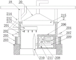
FIG. 1 is a schematic structural view of the present invention;
FIG. 2 is a schematic structural view of the grooving and slitting mechanism of the present invention;
FIG. 3 is a schematic diagram of a primary dustfall assembly of the present invention;
FIG. 4 is a schematic view of the installation of the housing and the annular movable block of the present invention;
fig. 5 is a schematic structural diagram of a settling tank of the present invention.
In the figure: 1. a frame; 2. a grooving and joint-cutting mechanism; 201. a noise reducing housing; 202. connecting the plate members; 203. a fixing frame; 204. a slide bar; 205. a support spring; 206. a drive box; 207. a rotating electric machine; 208. a first gear; 209. a rotating rod; 210. cutting a cutter; 211. a second gear; 212. a water distribution pipe; 213. an atomizing spray head; 214. a water delivery pipe; 215. a preliminary dust fall assembly; 21501. a housing; 21502. a waterproof cover; 21503. a partition plate; 21504. a motor; 21505. a rotating shaft; 21506. a third gear; 21507. a bevel gear; 21508. a first screen mesh; 21509. an annular groove; 21510. an annular movable block; 21511. a ring gear; 21512. a plug scraping assembly; 215121, a trough member; 215122, a wiper strip; 215123, a guide bar; 215124, a return spring; 21513. a second screen; 21514. a rod member; 21515. a cam; 21516. a drive bevel gear; 21517. an arc-shaped jacking block; 21518. a guide bar; 21519. connecting blocks; 21520. a spring; 3. a slider; 4. lifting the housing; 5. rotating the rod; 6. a drive motor; 7. a transmission gear; 8. a rotating drum; 9. a gear; 10. a connecting gear; 11. a threaded rod; 12. a weight box; 13. a water pump; 14. an air pump; 15. a settling water tank; 151. a water tank; 152. a water inlet; 153. a water outlet; 154. filtering with a screen; 155. a dust guide pipe; 156. an exhaust pipe; 157. an air inlet; 16. a water pumping pipe; 17. an air exhaust pipe; 18. a connecting member; 19. a moving wheel with a brake; 20. a cover body.
Detailed Description
The technical solutions in the embodiments of the present invention will be clearly and completely described below with reference to the drawings in the embodiments of the present invention, and it is obvious that the described embodiments are only a part of the embodiments of the present invention, and not all of the embodiments. All other embodiments, which can be derived by a person skilled in the art from the embodiments given herein without making any creative effort, shall fall within the protection scope of the present invention.
The invention provides a technical scheme that: a pavement slotting and slitting machine for sand-free concrete pavement with adjustable depth, please refer to fig. 1, which comprises a frame 1, wherein the outer walls of the left side and the right side of the frame 1 are respectively provided with a movable wheel 19 with a brake, when in use, a brake foot of the movable wheel 19 with the brake can be put down to avoid the misoperation of the frame 1, the middle parts of the left side and the right side of the frame 1 are respectively provided with a chute, a sliding block 3 is arranged in the chute in a sliding way, the center of the top of the frame 1 is provided with a rotating rod 5 through a bearing, the outer wall of the rotating rod 5 is provided with a connecting gear 10, the right side of the top of the frame 1 is provided with a driving motor 6, the tops of the rotating rod 5 and the driving motor 6 are respectively provided with a transmission gear 7, the outer walls of the two groups of transmission gears 7 are sleeved with chains, the, the gear 9 is meshed with one side opposite to the connecting gear 10, a threaded rod 11 is sleeved on an internal thread of the rotary drum 8, the driving motor 6 drives the transmission gear 7 and the rotary rod 5 to rotate, the rotary rod 5 drives the connecting gear 10, the gear 9 and the rotary drum 8 to rotate, the threaded rod 11 can extend out and retract, thereby changing the lifting movement of the lifting shell 4 and the slotting mechanism 2, when the slotting mechanism 2 descends, can perform grooving and cutting work, the descending height depends on the thickness of the pavement and the depth of the crack, the pavement near the crack is cut off smoothly, when filling and repairing are carried out, the appearance is attractive, the filling effect is good, the lifting shell 4 is fixed at the bottoms of the two groups of threaded rods 11, the sliding block 3 is fixed on the lifting shell 4, the four groups of connecting pieces 18 are arranged at the bottom of the lifting shell 4 in a rectangular array mode, the bottom of each group of connecting pieces 18 is fixed with the grooving and joint-cutting mechanism 2, and the top of the grooving and joint-cutting mechanism 2 is connected with the cover body 20;
referring to fig. 2, the slotting and lancing mechanism 2 includes a noise reduction housing 201 welded at the bottom of the connecting part 18, a mounting groove is arranged at the center of the top of the noise reduction housing 201, a primary dust fall assembly 215 is mounted in the mounting groove and mainly blocks debris to prevent the debris generated during lancing from blocking the air suction pump 14, the primary dust fall assembly 215 is located in the inner cavity of the cover body 20, a driving box 206 is welded at the bottom of the inner wall of the right side of the noise reduction housing 201, a rotating motor 207 is mounted on the inner wall of the top of the driving box 206, a first gear 208 is mounted on the left side of the rotating motor 207, mounting holes are formed in the bottoms of the left and right sides of the driving box 206, bearings are mounted in the mounting holes, rotating rods 209 are mounted in the inner rings of the two sets of bearings, a cutting tool 210 is arranged at the left end of the rotating rod 209, the rotating motor 207 drives the first, a second gear 211 is meshed with one side, opposite to the first gear 208, of the noise reduction shell 201, a fixing frame 203 is sleeved at the bottom of the outer wall of the noise reduction shell 201, connecting plate members 202 are welded at the middles of the left side and the right side of the noise reduction shell 201, mounting holes are formed in the front side and the rear side of the top of each connecting plate member 202, a sliding rod 204 is movably inserted in each mounting hole, the bottom of each sliding rod 204 is welded on the fixing frame 203, a supporting spring 205 is sleeved on the outer wall of each sliding rod 204, two ends of each supporting spring 205 are respectively connected to the corresponding connecting plate members 202 and the corresponding fixing frame 203, the supporting springs 205 reset to drive the fixing frames 203 to approach the ground, the cutting positions are sealed by the;
referring to fig. 3, the primary dust-settling assembly 215 includes a housing 21501, a waterproof case 21502 is connected to the left side of the housing 21501, a partition 21503 is disposed at the top of an inner cavity of the waterproof case 21502, a motor 21504 is mounted at the top of a partition 21503, a rotating shaft 21505 is mounted at the bottom of the motor 21504, a gear wheel 3 and a bevel gear 21507 are sequentially disposed on the outer wall of the rotating shaft 21505 from top to bottom, a screen wheel 21513 is movably inserted at the bottom of the inner cavity of the housing 21501, mounting holes are disposed at the bottoms of the left and right sides of the housing 21501, bearings are mounted in the mounting holes, rod members 21514 are mounted in the inner rings of the two sets of bearings, a transmission bevel gear 21516 is fixed at the left end of the rod member 21514, the right side of the bottom of the bevel gear 21507 is engaged with the top of the transmission bevel gear 21516, a cam 21515 is disposed on the outer wall of the inner cavity of the housing, a guide rod 21518 is movably inserted into the top of the connecting block 21519, the top of the guide rod 21518 is fixed to the bottom of the second screen mesh 21513, a spring 21520 is sleeved on the outer wall of the guide rod 21518, two ends of the spring 21520 are respectively fixed to the connecting block 21519 and the second screen mesh 21513, when the slitting work is performed, the motor 21504 drives the rotating shaft 21505 and the bevel gear 21507 to rotate, so that the bevel gear 21507, the transmission bevel gear 21516 and the rod 21514 are driven to rotate, the rod 21514 drives the cam 21515 to rotate, when the convex surface of the cam 21515 rotates to the top, the second screen mesh 21513 is pushed upwards to stretch the spring 21520, when the convex surface of the cam 21515 rotates away from the top, the spring 21520 resets to drive the second screen mesh 21513 to descend, so that the rotation of the cam 21515 can enable the second screen mesh 21513;
referring to fig. 3-4, an annular groove 21509 is formed in the top of the inner wall of the housing 21501, an annular movable block 21510 is slidably arranged in the annular groove 21509, a plug scraping assembly 21512 is arranged in the annular movable block 21510, a gear ring 21511 is sleeved on the outer wall of the annular movable block 21510, the gear ring 21511 is meshed with the opposite side of the gear ring 21506, an opening matched with the gear ring 21506 is formed in the housing 21501, a screen mesh 21508 is arranged at the top of the inner cavity of the housing 21501, the bottom of the screen mesh 21508 is attached to the top of the plug scraping assembly 21512, and the gear ring 21506 and the gear ring 21511 are driven by the rotating shaft 21505 to rotate, so that the annular movable block 21510 and the plug scraping assembly 21512 can rotate to scrape plugs at;
referring to fig. 4, the blockage scraping assembly 21512 includes a groove 215121 fixed in an inner cavity of the annular movable block 21510, a scraping strip 215122 is movably inserted in an inner cavity of the groove 215121, a guide rod 215123 is movably inserted in an inner wall of a bottom of the groove 215121, a top of the guide rod 215123 is fixed at a bottom of the scraping strip 215122, a return spring 215124 is sleeved on an outer wall of the guide rod 215123, two ends of the return spring 215124 are respectively connected to a bottom of the scraping strip 215122 and an inner wall of a bottom of the groove 215121, the scraping strip 215122 is attached to the first screen 21508, the groove 215121, the scraping strip 215122 and the guide rod 215123 are made of stainless steel, an extending portion of the scraping strip 215122 is one third of the height of the scraping strip 215122, a rubber strip is arranged at a top of the scraping strip 215122, the return spring 215124 can approach the scraping strip 215122 to the bottom of the first screen 21508 to scrape blockages at the bottom of the first screen 21508;
referring to fig. 1-5, a weight box 12, a water pump 13, an air pump 14 and a settling water tank 15 are sequentially installed on the inner wall of the bottom of a lifting shell 4 from left to right, the settling water tank 15 includes a water tank 151, an air exhaust pipe 156 is inserted into the top of the water tank 151, a water inlet 152 and a water outlet 153 are respectively formed in the top and the bottom of the right side of the water tank 151, an upper filter screen 154 and a lower filter screen 154 are arranged in the inner cavity of the water tank 151, the bottom filter screen 154 is located below the liquid level to mainly prevent the dusty turbidity from being extracted by the water exhaust pipe 16, the top filter screen 154 is located below the water inlet 152, the top filter screen 154 is located above the liquid level, an air inlet 157 is formed in the bottom of the left side of the water tank 151, a dust guide pipe 155 is connected to the right end of the air inlet 157, the other end of the, the other end of the extraction pipe 17 is connected to the cover body 20, the right end of the water suction pump 13 is connected with the water suction pipe 16, the other end of the water suction pipe 16 is connected to the water outlet 153, a water distribution pipe 212 is arranged above the inner cavity of the noise reduction shell 201, an atomizing nozzle 213 is arranged at the bottom of the water distribution pipe 212, the left end of the water distribution pipe 212 is connected with a water delivery pipe 214, the other end of the water delivery pipe 214 is connected to the left side of the water suction pump 13, the air suction pump 14 can enable the cover body 20 to generate negative pressure, smoke dust generated by cutting seams is delivered into a dust guide pipe 155 to perform dust falling work, air subjected to dust falling by clean water is filtered by a top filter screen 154 and then discharged by an exhaust pipe 156;
example (b):
1) the pavement joint cutting work is carried out, the rack 1 is moved to a crack position, then the driving motor 6 is started, the driving motor 6 drives the transmission gear 7 and the rotating rod 5 to rotate, the rotating rod 5 drives the connecting gear 10, the gear 9 and the rotary drum 8 to rotate, the threaded rod 11 can extend out and retract, the lifting shell 4 and the grooving mechanism 2 are further changed to carry out lifting movement, when the grooving mechanism 2 descends, the rotating motor 207 drives the gear I208 and the gear II 211 to rotate, the rotating rod 209 can drive the cutting tool 210 to rotate to perform joint cutting, the descending height depends on the thickness of the pavement and the depth of the crack, the pavement near the crack is cut off flatly, and the pavement is attractive and has better filling effect when filling and repairing are carried out;
2) the dust-settling work during lancing is carried out, the supporting spring 205 is reset to drive the fixing frame 203 to approach the ground, the fixing frame 203 closes the cutting position, the air suction pump 14 can enable the cover body 20 to generate negative pressure, smoke generated by lancing is sent into the dust guide pipe 155 to carry out dust-settling work, external air enters the noise reduction shell 201 through a through hole formed in the fixing frame 203 and a groove during lancing, the air pressure balance of the inner cavity of the noise reduction shell 201 is maintained, the air subjected to dust-settling by clean water is filtered by the top filter screen 154 and then is discharged through the exhaust pipe 156, the clean water is pumped out by the water suction pump 13 and then is sprayed out through the atomizing nozzle 213, and secondary dust settling can be carried;
3) anti-blocking work during dust fall, when slitting work is carried out, the motor 21504 drives the rotating shaft 21505 and the bevel gear 21507 to rotate, so that the bevel gear 21507, the transmission bevel gear 21516 and the rod member 21514 are driven to rotate, the rod member 21514 drives the cam 21515 to rotate, when the convex surface of the cam 21515 rotates to the top, the second screen 21513 is pushed upwards, the spring 21520 is stretched, when the convex surface of the cam 21515 rotates away from the top, the spring 21520 resets to drive the second screen 21513 to descend, so that the rotation of the cam 21515 can enable the second screen 21513 to vibrate up and down, a blockage clamped on the second screen 21513 is shaken down, the rotating shaft 21505 drives the third gear 21506 and the gear ring 21511 to rotate, the annular movable block 21510 and the blockage scraping assembly 21512 can rotate, the blockage at the bottom of the first screen 21508 is scraped, and the blockage situation is avoided during dust fall.
Although embodiments of the present invention have been shown and described, it will be appreciated by those skilled in the art that changes, modifications, substitutions and alterations can be made in these embodiments without departing from the principles and spirit of the invention, the scope of which is defined in the appended claims and their equivalents.
Claims (6)
1. The utility model provides a no sand concrete road surface of adjustable depth is with road surface fluting slotting machine, includes frame (1), frame (1) left and right sides outer wall all is equipped with area brake and removes wheel (19), its characterized in that: the middle part of the left side and the right side of the rack (1) is provided with a sliding groove, a sliding block (3) is arranged in the sliding groove, a rotating rod (5) is installed at the center of the top of the rack (1) through a bearing, a connecting gear (10) is arranged on the outer wall of the rotating rod (5), a driving motor (6) is arranged on the right side of the top of the rack (1), a transmission gear (7) is arranged at the top of the rotating rod (5) and the top of the driving motor (6), a chain is sleeved on the outer wall of the transmission gear (7), mounting holes are formed in the left side and the right side of the connecting part of the top of the rack (1) and the rotating rod (5), a bearing is installed in each mounting hole, a rotating cylinder (8) is fixed in each bearing inner ring, a gear (9) is fixed at the top of each, two sets of threaded rod (11) bottom is fixed with lift casing (4), sliding block (3) are fixed on lift casing (4), lift casing (4) bottom rectangle array is provided with four groups of connecting piece (18), and four groups connecting piece (18) bottom is fixed with fluting joint cutting mechanism (2), fluting joint cutting mechanism (2) top is connected with the cover body (20).
2. The depth-adjustable road surface slotting and slotting machine for sand-free concrete road surfaces as claimed in claim 1, wherein: slotting mechanism (2) including welding at the shell (201) of making an uproar of falling of connecting piece (18) bottom, it is provided with the mounting groove to fall shell (201) top center of making an uproar, installs preliminary dust fall subassembly (215) in the mounting groove, preliminary dust fall subassembly (215) are located cover body (20) inner chamber, the bottom welding of shell (201) right side inner wall of making an uproar has drive box (206), rotating electrical machines (207) are installed to drive box (206) top inner wall, gear (208) are installed in rotating electrical machines (207) left side, the bottom of drive box (206) left and right sides all is provided with the mounting hole, installs the bearing in the mounting hole, installs bull stick (209) in two sets of bearing inner circles, bull stick (209) left end is provided with cutting tool (210), bull stick (209) are located the outer wall of drive box (206) inner chamber part and are, gear two (211) and the meshing of the relative one side of gear one (208), it is equipped with fixed frame (203) to fall outer shell (201) outer wall bottom cover of making an uproar, the middle part of falling the outer shell (201) left and right sides of making an uproar all welds and connects plate (202), both sides all are provided with the mounting hole around connecting plate (202) top, and the activity is inserted in the mounting hole and is equipped with slide bar (204), the welding of slide bar (204) bottom is on fixed frame (203), slide bar (204) outer wall cover is equipped with supporting spring (205), the both ends of supporting spring (205) are connected respectively on connecting plate (202) and fixed frame (203).
3. The depth-adjustable road surface slotting and slotting machine for sand-free concrete road surfaces as claimed in claim 2, wherein the slotting machine comprises: the preliminary dust fall assembly (215) comprises a shell (21501), a waterproof cover (21502) is connected to the left side of the shell (21501), a partition plate (21503) is arranged at the top of an inner cavity of the waterproof cover (21502), a motor (21504) is installed at the top of the partition plate (21503), a rotating shaft (21505) is installed at the bottom of the motor (21504), a gear III (21506) and a bevel gear (21507) are sequentially arranged on the outer wall of the rotating shaft (21505) from top to bottom, a screen II (21513) is movably inserted at the bottom of the inner cavity of the shell (21501), mounting holes are formed in the bottoms of the left side and the right side of the shell (21501), bearings are installed in the mounting holes, rod pieces (21514) are installed in two sets of bearing inner rings, a transmission bevel gear (21516) is fixed to the left end of each rod piece (21514), the right side of the bottom of each bevel gear (21507) is meshed with the top of, the center of the bottom of the second screen (21513) is fixed with an arc-shaped top block (21517), the bottom of the arc-shaped top block (21517) is attached to the top of the cam (21515), connecting blocks (21519) are fixed to the middle portions of the front side and the rear side of the shell (21501), guide rods (21518) are movably inserted into the tops of the connecting blocks (21519), the tops of the guide rods (21518) are fixed to the bottom of the second screen (21513), springs (21520) are sleeved on the outer walls of the guide rods (21518), and two ends of the springs (21520) are fixed to the connecting blocks (21519) and the second screen (21513) respectively.
4. The depth-adjustable road surface slotting and slotting machine for sand-free concrete road surfaces as claimed in claim 3, wherein the slotting machine comprises: casing (21501) inner wall top is provided with annular groove (21509), it is provided with annular movable block (21510) to slide in annular groove (21509), it strikes off subassembly (21512) to be provided with the jam in annular movable block (21510), annular movable block (21510) outer wall cover is equipped with ring gear (21511), ring gear (21511) and the meshing of three (21506) relative one side of gear, be provided with on casing (21501) with three (21506) matched with opening of gear, casing (21501) inner chamber top is provided with screen cloth (21508), screen cloth (21508) bottom strikes off subassembly (21512) top with the jam and laminates.
5. The depth-adjustable road surface slotting and slitting machine for sand-free concrete road surfaces as claimed in claim 4, wherein the slotting machine comprises: the plug strikes off subassembly (21512) including fixing groove spare (215121) at annular movable block (21510) inner chamber, groove spare (215121) inner chamber activity is inserted and is equipped with scrapes strip (215122), groove spare (215121) bottom inner wall activity is inserted and is equipped with guide bar (215123), guide bar (215123) top is fixed in scraping strip (215122) bottom, guide bar (215123) outer wall cover is equipped with reset spring (215124), reset spring (215124)'s both ends are connected respectively on scraping strip (215122) bottom and groove spare (215121) bottom inner wall, scrape strip (215122) laminating on screen cloth (21508), groove spare (215121), scrape strip (215122) and guide bar (215123) and be the stainless steel and make, the extension of scraping strip (215122) is the third of scraping strip (215122) height, it is provided with the rubber strip to scrape strip (215122) top.
6. The depth-adjustable road surface slotting and slotting machine for sand-free concrete road surfaces as claimed in claim 5, wherein the slotting machine comprises: the inner wall of the bottom of the lifting shell (4) is sequentially provided with a weight box (12), a water suction pump (13), an air suction pump (14) and a sedimentation water tank (15) from left to right, the sedimentation water tank (15) comprises a water tank (151), an exhaust pipe (156) is inserted into the top of the water tank (151), the top and the bottom of the right side of the water tank (151) are respectively provided with a water inlet (152) and a water outlet (153), the inner cavity of the water tank (151) is provided with an upper filter screen and a lower filter screen (154), the bottom of the water tank (151) is positioned below the liquid level, the top of the water tank (154) is positioned below the water inlet (152), the top of the water tank (151) is positioned above the liquid level, the bottom of the left side of the water tank (151) is provided with an air inlet (157), the right end of the air inlet, lead dirt pipe (155) and be located the liquid level below, air inlet (157) are connected through pipeline and aspiration pump (14) left side, aspiration pump (14) left side is connected with aspiration tube (17), the other end of aspiration tube (17) is connected on the cover body (20), suction pump (13) right-hand member is connected with suction pipe (16), the other end of suction pipe (16) is connected on delivery port (153), it is provided with water distributor (212) to fall outer shell (201) inner chamber top of making an uproar, water distributor (212) bottom is provided with atomizer (213), water distributor (212) left end is connected with raceway (214), the left side at suction pump (13) is connected to the other end of raceway (214).
Priority Applications (1)
| Application Number | Priority Date | Filing Date | Title |
|---|---|---|---|
| CN202011526156.5A CN112695600A (en) | 2020-12-22 | 2020-12-22 | Sand-free concrete pavement slotting and slotting machine with adjustable depth |
Applications Claiming Priority (1)
| Application Number | Priority Date | Filing Date | Title |
|---|---|---|---|
| CN202011526156.5A CN112695600A (en) | 2020-12-22 | 2020-12-22 | Sand-free concrete pavement slotting and slotting machine with adjustable depth |
Publications (1)
| Publication Number | Publication Date |
|---|---|
| CN112695600A true CN112695600A (en) | 2021-04-23 |
Family
ID=75510113
Family Applications (1)
| Application Number | Title | Priority Date | Filing Date |
|---|---|---|---|
| CN202011526156.5A Pending CN112695600A (en) | 2020-12-22 | 2020-12-22 | Sand-free concrete pavement slotting and slotting machine with adjustable depth |
Country Status (1)
| Country | Link |
|---|---|
| CN (1) | CN112695600A (en) |
Cited By (3)
| Publication number | Priority date | Publication date | Assignee | Title |
|---|---|---|---|---|
| CN113529554A (en) * | 2021-09-15 | 2021-10-22 | 山东省路桥集团有限公司 | Environment-friendly joint cutting device with controllable joint cutting depth for bridge road construction |
| CN113550222A (en) * | 2021-08-11 | 2021-10-26 | 海堂 | Town road construction is with repairing way and making an uproar device of falling |
| CN114481786A (en) * | 2022-03-05 | 2022-05-13 | 王少波 | Grooving device with dustproof function for road construction |
Citations (8)
| Publication number | Priority date | Publication date | Assignee | Title |
|---|---|---|---|---|
| KR101746305B1 (en) * | 2015-12-30 | 2017-06-12 | 정세영 | A Moving Dust Collector for Tunnel Operations of Using Engine |
| CN208362870U (en) * | 2018-07-04 | 2019-01-11 | 河南省亚欧起重设备有限公司 | A kind of spray thrower for concrete road surface |
| CN209362062U (en) * | 2018-12-27 | 2019-09-10 | 苏州中用环保科技有限公司 | A kind of boiler flue gas purification bag filter |
| CN209952428U (en) * | 2019-04-04 | 2020-01-17 | 南通巨大机械制造有限公司 | Dust collector who has clean function of filter screen is used in building materials workshop |
| KR102069546B1 (en) * | 2019-02-14 | 2020-01-28 | (주)깨끗한도시 | Garbage truck for removing non-point pollutants on roads |
| CN210186801U (en) * | 2019-05-16 | 2020-03-27 | 徐州天蓝臭氧设备有限公司 | Environment-friendly industrial waste gas purification device |
| CN210596956U (en) * | 2019-08-21 | 2020-05-22 | 张兰升 | Height self-adjusting's highway road surface cutting device |
| CN211328543U (en) * | 2019-08-25 | 2020-08-25 | 何美美 | Self-cleaning cloth bag dust removal device for building material workshop |
-
2020
- 2020-12-22 CN CN202011526156.5A patent/CN112695600A/en active Pending
Patent Citations (8)
| Publication number | Priority date | Publication date | Assignee | Title |
|---|---|---|---|---|
| KR101746305B1 (en) * | 2015-12-30 | 2017-06-12 | 정세영 | A Moving Dust Collector for Tunnel Operations of Using Engine |
| CN208362870U (en) * | 2018-07-04 | 2019-01-11 | 河南省亚欧起重设备有限公司 | A kind of spray thrower for concrete road surface |
| CN209362062U (en) * | 2018-12-27 | 2019-09-10 | 苏州中用环保科技有限公司 | A kind of boiler flue gas purification bag filter |
| KR102069546B1 (en) * | 2019-02-14 | 2020-01-28 | (주)깨끗한도시 | Garbage truck for removing non-point pollutants on roads |
| CN209952428U (en) * | 2019-04-04 | 2020-01-17 | 南通巨大机械制造有限公司 | Dust collector who has clean function of filter screen is used in building materials workshop |
| CN210186801U (en) * | 2019-05-16 | 2020-03-27 | 徐州天蓝臭氧设备有限公司 | Environment-friendly industrial waste gas purification device |
| CN210596956U (en) * | 2019-08-21 | 2020-05-22 | 张兰升 | Height self-adjusting's highway road surface cutting device |
| CN211328543U (en) * | 2019-08-25 | 2020-08-25 | 何美美 | Self-cleaning cloth bag dust removal device for building material workshop |
Cited By (5)
| Publication number | Priority date | Publication date | Assignee | Title |
|---|---|---|---|---|
| CN113550222A (en) * | 2021-08-11 | 2021-10-26 | 海堂 | Town road construction is with repairing way and making an uproar device of falling |
| CN113550222B (en) * | 2021-08-11 | 2024-03-22 | 深圳市瑞荣达实业有限公司 | Road repair noise reduction device for municipal road construction |
| CN113529554A (en) * | 2021-09-15 | 2021-10-22 | 山东省路桥集团有限公司 | Environment-friendly joint cutting device with controllable joint cutting depth for bridge road construction |
| CN113529554B (en) * | 2021-09-15 | 2021-12-21 | 山东省路桥集团有限公司 | Environment-friendly joint cutting device with controllable joint cutting depth for bridge road construction |
| CN114481786A (en) * | 2022-03-05 | 2022-05-13 | 王少波 | Grooving device with dustproof function for road construction |
Similar Documents
| Publication | Publication Date | Title |
|---|---|---|
| CN112695600A (en) | Sand-free concrete pavement slotting and slotting machine with adjustable depth | |
| CN216617484U (en) | Anti-clogging resin sand screen | |
| CN112827588A (en) | Material collecting and processing device and method for intelligent manufacturing | |
| CN110410133B (en) | Portable small-area dust removal device for underground coal mine | |
| CN208167630U (en) | A kind of road administration environmental protection catkin removing machine | |
| CN216369456U (en) | Dust fall equipment is used in reclaimed sand production | |
| CN115897698A (en) | Reservoir underwater walking type sludge suction and discharge device | |
| CN215748077U (en) | Scraper type chip removal machine | |
| CN214262905U (en) | A cleaning device for producing PC component mould platform | |
| CN112515566A (en) | Be used for workshop deashing equipment | |
| CN213408024U (en) | Chambered pulse bag type dust collector | |
| CN110656610B (en) | Road ponding treatment facility for municipal administration | |
| CN114307486A (en) | Building construction environmental protection dust device | |
| CN210876426U (en) | Stainless steel sintering net sweeps device | |
| CN209243643U (en) | A kind of green construction road cleaning device | |
| CN108722073B (en) | Road construction is with earthwork excavation raise dust processing apparatus | |
| CN210021373U (en) | Improved micro-filter | |
| CN216999362U (en) | Crack pouring auxiliary equipment for bridge construction | |
| CN210560300U (en) | Natural gas conveying air pressure adjusting device | |
| CN213195504U (en) | Crushing regenerator | |
| CN219701352U (en) | Filter for separating and extracting water slag | |
| CN216788511U (en) | Oil pump with double oil outlets | |
| CN214552187U (en) | Waste gas recovery equipment | |
| CN216475282U (en) | Silt cleaning device is used in river course water environment prevention and cure | |
| CN219972893U (en) | Pipeline slotting device |
Legal Events
| Date | Code | Title | Description |
|---|---|---|---|
| PB01 | Publication | ||
| PB01 | Publication | ||
| SE01 | Entry into force of request for substantive examination | ||
| SE01 | Entry into force of request for substantive examination | ||
| RJ01 | Rejection of invention patent application after publication | ||
| RJ01 | Rejection of invention patent application after publication |
Application publication date: 20210423 |