CN112681627A - Energy-saving building - Google Patents
Energy-saving building Download PDFInfo
- Publication number
- CN112681627A CN112681627A CN202110032481.4A CN202110032481A CN112681627A CN 112681627 A CN112681627 A CN 112681627A CN 202110032481 A CN202110032481 A CN 202110032481A CN 112681627 A CN112681627 A CN 112681627A
- Authority
- CN
- China
- Prior art keywords
- groove
- water collecting
- fixedly connected
- top end
- collecting pipe
- Prior art date
- Legal status (The legal status is an assumption and is not a legal conclusion. Google has not performed a legal analysis and makes no representation as to the accuracy of the status listed.)
- Pending
Links
Images


Abstract
The invention discloses an energy-saving building, which comprises a building body, wherein a water collecting and storing mechanism is arranged at the top end of the building body, a filtering and cleaning mechanism is arranged at the top end of the building body, a switching mechanism is arranged inside the building body, the water collecting and storing mechanism comprises an attic, the attic is arranged at the top end inside the building body, and a water storage tank is fixedly connected to the center of the surface of the bottom end inside the attic: carry out the retaining at partial regional roof, can effective water economy resource, reduce the energy consumption when supplying water simultaneously, when collecting the rainwater, carry out the prefilter through the net piece on sleeve surface, the doctor-bar is scraped the net piece and is wiped away, the mud that is blockked drops to in the dirty groove of collection, prevent to block up, through setting up the automatic drainage or catchment of controlling of switching mechanism, when the inside liquid level of water storage box is lower, the rainwater gets into the inside of water storage box, when the liquid level risees, the rainwater passes through the drainage outer tube and discharges, through liquid level floater automatic control retaining and drainage.
Description
Technical Field
The invention relates to the technical field of buildings, in particular to an energy-saving building.
Background
The energy-saving building refers to a low-energy-consumption building designed by researching building planning subareas, groups, monomers, building orientation, space, solar radiation, wind direction and external space environment according to a basic method for climate design and energy saving. The total amount of building energy consumption of 1/3 China, which accounts for the total social energy consumption, is increased year by year, and the proportion of the total energy consumption is increased to 27.45 percent from 10 percent at the end of seventies of the last century. And the building energy consumption of the international developed countries generally accounts for about 33 percent of the total national energy consumption. Based on the conclusion, research of science and technology department of the national ministry of construction shows that with the acceleration of urbanization and the improvement of the quality of life of people, the building energy consumption proportion of China finally rises to about 35%. With such a large specific gravity, the building energy consumption becomes a soft rib for economic development in China.
In order to save energy, different forms of energy-saving buildings are designed in various places through local natural environments, and the energy-saving buildings comprise wind energy utilization, solar power generation, rainwater collection and the like, wherein the wind energy and the solar energy are converted into electric energy to be directly used, the rainwater is simply treated after being collected and can be used for mopping, flushing a toilet and the like, energy consumption during water supply of a high-rise building is saved, rainwater resources are effectively utilized, when the existing energy-saving buildings collect rainwater, dust and sundries on the roof can block a collecting device, so that the collected rainwater is rich in impurities and dust, excessive filtering consumables are consumed during subsequent treatment, and meanwhile, accumulated water on the roof is difficult to drain in time after a water storage device is full.
Disclosure of Invention
The invention aims to provide an energy-saving building to solve the problems in the background technology.
In order to achieve the purpose, the invention provides the following technical scheme: the energy-saving building comprises a building body, wherein a water collecting and storing mechanism is arranged on the top end of the building body, a filtering and cleaning mechanism is arranged on the top end of the building body, and a switching mechanism is arranged in the building body.
Preferably, the water collecting and storing mechanism comprises an attic, the attic is arranged at the top end inside the building body, a water storage tank is fixedly connected to the center of the surface of the bottom end inside the attic, a compensating valve is fixedly communicated with the center of the surface of the top end of the water storage tank, a water collecting tank is arranged at the top end of the building body, and a drainage groove is formed in an extending edge of the bottom end inside the water collecting tank.
Preferably, it includes the dirty groove of collection to cross to filter the clearance mechanism, the dirty groove of collection is seted up on the bottom surface of drainage groove, the slot has been seted up to the bottom surface center department in the dirty groove of collection, the inside fixed grafting of slot has the collector pipe, the sealed setting of junction of collector pipe and slot, the fixed cover of top surface of collector pipe has connect the sleeve, telescopic shape is cylindrical, telescopic inside bottom is linked together with the top of collector pipe, the sleeve has been close to the lateral wall surface on top and has seted up the annular, the inside fixed grafting of annular has the net piece, telescopic top surface center department fixedly connected with carousel bearing, the dirt of collection groove is collected to the dirt of crossing, the dirt of collection
The upper surface of the turntable bearing is rotatably connected with a circular plate, the periphery of the bottom surface of the circular plate is fixedly connected with a plurality of scraping blades, the bottom ends of the scraping blades are fixedly connected with a same bottom plate, the shape of the bottom plate is circular, the surface center of the bottom plate is provided with a through groove, the lower surface of the bottom plate is fixedly connected with an annular tooth groove, a through hole is formed in the surface of one side of the inner wall of the water collecting pipe close to the top end, the inside of the through hole is rotatably connected with a sealing bearing, the inside of the sealing bearing is rotatably connected with a rotating shaft, one end of the rotating shaft is fixedly connected with a rotating wheel, the rotating wheel is positioned inside the water collecting pipe, the inside top end of the water collecting pipe is provided with a funnel-shaped diversion trench, one end of the rotating shaft far away, the drain is located inside the attic.
Preferably, the switching mechanism includes a side groove, the side groove is formed in the surface of the side wall of the attic, a cylindrical barrel is sleeved on the outer surface of the bottom end of the water collecting pipe, a sealing sliding groove is formed between the upper surface and the lower surface of the cylindrical barrel, a discharge hole is formed in the surface of one side of the bottom end of the water collecting pipe, a discharge groove is formed in the bottom end of the surface of one side, close to the discharge hole, of the cylindrical barrel, a first hose is fixedly connected to the surface of one end, close to the discharge groove, of the cylindrical barrel through a pipe connector, a drainage outer pipe is fixedly inserted into the building body through a groove, a collection hole is formed in the end, far away
The collecting tank is arranged on the side surface, one end, close to the collecting tank, of the cylindrical barrel is fixedly connected with a second hose through a pipe connector, a sliding hole is formed in the top end surface, close to the side groove, of the water storage tank, a sliding rod is connected inside the sliding hole in a sliding mode, a liquid level floating ball is fixedly connected to the bottom end of the sliding rod, a cross rod is fixedly connected to the top end of the sliding rod, one end, far away from the sliding rod, of the cross rod is fixedly connected with the outer wall of the cylindrical barrel, a collecting pipe is fixedly communicated with the side surface of one end, close to the sliding hole, of the water storage tank, and.
Preferably, the scraping sheets are in contact with the outer surface of the net piece, the water collecting pipe is located inside the through groove and is in rotating connection, and the gear is meshed with the annular tooth groove.
Preferably, the top end of the side groove is communicated with the slot, and the bottom end of the water collecting pipe is located inside the side groove.
Preferably, the cross section of the sealing chute is circular, and the sealing chute is connected with the bottom end of the water collecting pipe in a sliding manner.
Preferably, the discharge groove is matched with the discharge hole, the first hose is communicated with the discharge groove, one end of the outer drainage pipe is fixedly communicated with the first hose, the collecting tank is communicated with the second hose, and the collecting tank is matched with the collecting hole.
Compared with the prior art, the invention has the beneficial effects that: store water at partial region roof, can effective water economy resource, reduce the energy consumption when supplying water simultaneously, when collecting the rainwater, carry out prefilter through the net piece on sleeve surface, the rainwater enters into telescopic inside through the net piece, erodees one side of runner when the rainwater descends, and the rainwater drives the runner and rotates, finally drives
The scraping piece is rotatory, and the scraping piece drives the plectane rotation on top simultaneously, and the scraping piece is scraped the net piece and is wiped away, and the mud that is blockked drops in the dirty groove of collection, prevents to block up.
Control drainage or catchment through setting up switching mechanism, when the liquid level of water storage box inside is lower, the liquid level floater is unsettled this moment, the horizontal pole is located the extreme lower position, make collection hole and collecting vat align, the rainwater passes through the collector pipe decline, and loop through the collection hole, the collecting vat gets into the inside of water storage box, when the liquid level risees, the liquid level floater rises, it shifts up to drive the slide bar, the slide bar drives the horizontal pole and shifts up, the horizontal pole drives a cylinder section of thick bamboo and goes up, make the collecting vat misplace with the collection hole, and make the drain tank align with the discharge hole, the rainwater passes through the drainage outer tube and discharges.
Drawings
FIG. 1 is a front view of the structure of the present invention;
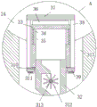
FIG. 2 is an enlarged view of a portion A of FIG. 1 according to the present invention;
FIG. 3 is an enlarged view of the portion B of FIG. 1;
FIG. 4 is a side view of the filter cleaning mechanism of the present invention;
FIG. 5 is a bottom view of the base plate structure of the present invention;
fig. 6 is a perspective view of the sleeve structure of the present invention.
In the figure: 1. a building body; 2. a water collecting and storing mechanism; 21. an attic; 22. a water storage tank; 23. a water collecting tank; 24. a drainage groove; 25. a compensation valve; 3. an over-filtration cleaning mechanism; 31. a slot; 32. a water collection pipe; 33. a sleeve; 34. a ring groove; 35. a mesh sheet; 36. a turntable bearing; 37. a circular plate; 38. scraping a blade; 39. a base plate; 310. a through groove; 311. an annular gullet; 312. a rotating wheel; 313. a rotating shaft; 314. a through hole; 315. sealing the bearing; 316. a gear; 317. a sewage collecting tank; 318. a sewage draining outlet; 4. a switching mechanism; 41. a side groove; 42. a cylindrical barrel; 43. sealing the chute; 44. a discharge hole; 45. a collection well; 46. a discharge tank; 47. a first hose; 48. an outer drainage pipe; 49. collecting tank; 410. a second hose; 411. a collection pipe; 412. a cross bar; 413. a slide bar; 414. a slide hole; 415. and a liquid level floating ball.
Detailed Description
The technical solutions in the embodiments of the present invention will be clearly and completely described below with reference to the drawings in the embodiments of the present invention, and it is obvious that the described embodiments are only a part of the embodiments of the present invention, and not all of the embodiments. All other embodiments, which can be derived by a person skilled in the art from the embodiments given herein without making any creative effort, shall fall within the protection scope of the present invention.
Referring to fig. 1-6, the present invention provides a technical solution: the energy-saving building comprises a building body 1, wherein a water collecting and storing mechanism 2 is arranged at the top end of the building body 1, a filtering and cleaning mechanism 3 is arranged at the top end of the building body 1, and a switching mechanism 4 is arranged in the building body 1.
The over-filtering cleaning mechanism 3 comprises a dirt collecting groove 317, the dirt collecting groove 317 is formed in the bottom end surface of the drainage groove 24, a slot 31 is formed in the center of the bottom end surface of the dirt collecting groove 317, a water collecting pipe 32 is fixedly inserted in the slot 31, the joint of the water collecting pipe 32 and the slot 31 is sealed, a sleeve 33 is fixedly sleeved on the outer surface of the top end of the water collecting pipe 32, the sleeve 33 is cylindrical, the bottom end of the inner portion of the sleeve 33 is communicated with the top end of the water collecting pipe 32, an annular groove 34 is formed in the side wall surface of the sleeve 33 close to the top end, a net 35 is fixedly inserted in the annular groove 34, a turntable bearing 36 is fixedly connected to the center of the top end surface of the sleeve 33, a circular plate 37 is rotatably connected to the upper surface of the turntable bearing 36, a plurality of scraping blades 38 are fixedly connected to the, the bottom plate 39 is circular, a through groove 310 is formed in the center of the surface of the bottom plate 39, an annular tooth groove 311 is fixedly connected to the lower surface of the bottom plate 39, a through hole 314 is formed in the surface of one side of the inner wall of the water collecting pipe 32 close to the top end, a sealing bearing 315 is rotatably connected to the inside of the through hole 314, a rotating shaft 313 is rotatably connected to the inside of the sealing bearing 315, a rotating wheel 312 is fixedly connected to one end of the rotating shaft 313, the rotating wheel 312 is located inside the water collecting pipe 32, a funnel-shaped guide groove is formed in the top end of the inside of the water collecting pipe 32, a gear 316 is fixedly connected to one end of the rotating shaft 313, which is far away from the rotating wheel 312, the gear 316 is located outside the water collecting pipe 32, a sewage discharge outlet 318 is formed in the surface of one side of the, the rainwater enters into the inside of sleeve 33 through net piece 35, descend through collector pipe 32, one side that erodes runner 312 when the rainwater descends drives runner 312 and rotates, it is rotatory finally to drive bottom plate 39, bottom plate 39 drives doctor-bar 38 rotatory, doctor-bar 38 drives the plectane 37 on top rotatory simultaneously, doctor-bar 38 is scraped net piece 35 and is wiped away, the mud that is blockked falls in collection dirt groove 317, can be through opening drain 318, perhaps with in drain 318 passes through the valve access drainage system, reach the effect of discharging mud.
Switching mechanism 4 includes side channel 41, side channel 41 sets up the lateral wall surface at attic 21, cylinder 42 has been cup jointed to water collection pipe 32's bottom surface, sealed spout 43 has been seted up between cylinder 42's the upper and lower surface, discharge hole 44 has been seted up to water collection pipe 32's bottom side surface, cylinder 42 has been close to discharge hole 44 side surface bottom and has been seted up discharge groove 46, cylinder 42 is close to the one end surface of discharge groove 46 and has been passed through the first hose 47 of connector fixedly connected with, building 1's inside has drainage outer tube 48 through the fixed grafting of fluting, discharge hole 45 has been seted up to the one end that discharge hole 44 was kept away from to water collection pipe 32's bottom, cylinder 42 has been close to one side surface of collection hole 45 and has been seted up 49, cylinder 42 is close to
The device is fixedly connected with a second hose 410, a sliding hole 414 is formed in the top end surface of one side of the water storage tank 22 close to the side groove 41, a sliding rod 413 is connected in the sliding hole 414 in a sliding mode, a liquid level floating ball 415 is fixedly connected to the bottom end of the sliding rod 413, a cross rod 412 is fixedly connected to the top end of the sliding rod 413, one end, far away from the sliding rod 413, of the cross rod 412 is fixedly connected with the outer wall of the cylindrical barrel 42, a collecting pipe 411 is fixedly communicated with the side surface of one end, close to the sliding hole 414, of the water storage tank 22, one end, far away from the water storage tank 22, of the collecting pipe 411 is fixedly communicated with the second hose 410 through a pipe connector, when the liquid level in the water storage tank 22 is low, the collecting hole 45 is aligned with the collecting tank 49 and enters the water storage tank 22, when, by offsetting the collection trough 49 from the collection aperture 45 and aligning the discharge trough 46 with the discharge aperture 44, rainwater drains through the outer drain tube 48, with automatic control of the water accumulation and drainage by the level float 415.
The scraping blades 38 are arranged in contact with the outer surface of the net sheet 35, the water collecting pipe 32 is located inside the through groove 310 and is connected in a rotating mode, and the gear 316 is meshed with the annular tooth groove 311, so that the scraping blades 38 are driven to clean the surface of the net sheet 35 conveniently.
The top end of the side groove 41 is communicated with the slot 31, and the bottom end of the water collecting pipe 32 is positioned inside the side groove 41, so that rainwater can be collected conveniently.
The cross-sectional shape of sealed spout 43 is circular, and sealed spout 43 and the bottom sliding connection of collector pipe 32 are convenient for switch the interface through the lift of a cylinder 42, carry out catchmenting and drainage.
The discharge groove 46 is matched with the discharge hole 44, the first hose 47 is communicated with the discharge groove 46, one end of the outer drain pipe 48 is fixedly communicated with the first hose 47, and the collecting tank 49 is connected with the second hose 410
And the collecting groove 49 is matched with the collecting hole 45, so that rainwater can be collected or discharged conveniently.
Specifically, when the invention is used, rainwater is stored on the roof of a part of areas, so that water resources can be effectively saved, and energy consumption in water supply is reduced, wherein a water collecting tank 23 on the roof collects rainwater and then discharges the rainwater into a drainage groove 24, and finally enters a water storage tank 22 of an attic 21, the rainwater descends through natural gravity after being simply processed for use by a user, a compensating valve 25 is arranged in the water storage tank 22 and is used for compensating the air pressure change in the tank body when the liquid level rises or falls, wherein the water overflows into a sewage collecting groove 317, primary filtration is carried out through a net 35 on the surface of a sleeve 33, the rainwater enters the sleeve 33 through the net 35 and descends through a water collecting pipe 32, and the inside of the water collecting pipe 32 close to the top end is arranged in a semi-funnel shape when the rainwater passes through the water collecting pipe 32,
when rainwater falls, the rainwater washes one side of the rotating wheel 312, the rotating wheel 312 is driven by the rainwater to rotate, the rotating shaft 313 is driven by the rotating wheel 312 to rotate, the gear 316 drives the annular tooth groove 311 to rotate, the annular tooth groove 311 drives the bottom plate 39 to rotate, the bottom plate 39 drives the scraping blade 38 to rotate, the scraping blade 38 simultaneously drives the circular plate 37 at the top end to rotate, the scraping blade 38 scrapes the net piece 35, the blocked mud falls into the sewage collecting groove 317, the effect of discharging the mud can be achieved by opening the sewage discharge opening 318 or connecting the sewage discharge opening 318 into a drainage system through a valve, when the liquid level in the water storage tank 22 is low, the sliding rod 413 is positioned at the position close to the top end in the water storage tank 22 due to the limiting of the transverse rod 412, the liquid level floating ball 415 is suspended at the moment, the transverse rod 412 is positioned at, rainwater descends through the water collecting pipe 32 and sequentially passes through the collecting hole 45 and the collecting groove 49, the second hose 410 and the collecting pipe 411 enter the water storage tank 22, when the liquid level rises, the liquid level floating ball 415 rises to drive the sliding rod 413 to move upwards, the sliding rod 413 drives the cross rod 412 to move upwards, the cross rod 412 drives the cylindrical barrel 42 to slide upwards, the collecting groove 49 and the collecting hole 45 are staggered, the drainage groove 46 and the drainage hole 44 are aligned, rainwater is drained through the drainage outer pipe 48, and water storage and drainage are automatically controlled through the liquid level floating ball 415.
In the description of the present invention, it is to be understood that the terms "coaxial," "bottom," "one end," "top," "middle," "other end," "upper," "one side," "top," "inner," "front," "center," "two ends," and the like are used in the orientations and positional relationships indicated in the drawings for the purpose of convenience and simplicity of description, and do not indicate or imply that the referenced device or element must have a particular orientation, be constructed and operated in a particular orientation, and thus not be necessarily oriented or oriented
And are to be construed as limiting the invention.
Furthermore, the terms "first", "second", "third", "fourth" are used for descriptive purposes only and are not to be construed as indicating or implying a relative importance or implicitly indicating the number of technical features indicated, whereby the features defined as "first", "second", "third", "fourth" may explicitly or implicitly include at least one such feature.
In the present invention, unless otherwise expressly specified or limited, the terms "mounted," "disposed," "connected," "secured," "screwed" and the like are to be construed broadly, e.g., as meaning fixedly connected, detachably connected, or integrally formed; can be mechanically or electrically connected; the terms may be directly connected or indirectly connected through an intermediate, and may be communication between two elements or interaction relationship between two elements, unless otherwise specifically limited, and the specific meaning of the terms in the present invention will be understood by those skilled in the art according to specific situations.
Although embodiments of the present invention have been shown and described, it will be appreciated by those skilled in the art that changes, modifications, substitutions and alterations can be made in these embodiments without departing from the principles and spirit of the invention, the scope of which is defined in the appended claims and their equivalents.
Claims (8)
1. The energy-saving building comprises a building body (1) and is characterized in that a water collecting and storing mechanism (2) is arranged at the top end of the building body (1), a filtering and cleaning mechanism (3) is arranged at the top end of the building body (1), and a switching mechanism (4) is arranged in the building body (1).
2. An energy saving building according to claim 1 wherein: catchment retaining mechanism (2) include loft (21), the top in the building body (1) is seted up in loft (21), the inside bottom surface center fixedly connected with water storage box (22) of loft (21), fixed intercommunication in water storage box (22) top surface center department has compensating valve (25), catch basin (23) have been seted up on the top of the building body (1), drainage groove (24) have been seted up on the inside bottom of catch basin (23) extension limit.
3. An energy saving building according to claim 1 wherein: the filter cleaning mechanism (3) comprises a dirt collecting groove (317), the dirt collecting groove (317) is arranged on the bottom surface of the drainage groove (24), a slot (31) is formed in the center of the bottom surface of the dirt collecting groove (317), a water collecting pipe (32) is fixedly inserted into the inner part of the slot (31), the water collecting pipe (32) is hermetically arranged at the joint of the slot (31), a sleeve (33) is fixedly connected to the outer surface of the top end of the water collecting pipe (32), the sleeve (33) is cylindrical, the inner bottom end of the sleeve (33) is communicated with the top end of the water collecting pipe (32), an annular groove (34) is formed in the surface of the side wall, close to the top end, of the sleeve (33), a net piece (35) is fixedly inserted into the inner part of the annular groove (34), a turntable bearing (36) is fixedly connected to the center of the surface of the top end of the sleeve (33), and a circular plate (37) is rotatably connected to the, the bottom end surface of the circular plate (37) is fixedly connected with a plurality of scraping blades (38) all around, the bottom ends of the scraping blades (38) are fixedly connected with the same bottom plate (39), the bottom plate (39) is circular, a through groove (310) is formed in the center of the surface of the bottom plate (39), an annular tooth groove (311) is fixedly connected to the lower surface of the bottom plate (39), a through hole (314) is formed in the surface of one side, close to the top end, of the inner wall of the water collecting pipe (32), the through hole (314) is rotatably connected with a sealing bearing (315), a rotating shaft (313) is rotatably connected to the inside of the sealing bearing (315), one end of the rotating shaft (313) is fixedly connected with a rotating wheel (312), the rotating wheel (312) is located inside the water collecting pipe (32), a funnel-shaped diversion trench is formed in the top end of the water collecting pipe (32), and one end, far away, the gear (316) is located outside the water collecting pipe (32), a sewage draining outlet (318) is formed in the surface of one side of the bottom end of the sewage collecting groove (317), and the sewage draining outlet (318) is located inside the attic (21).
4. An energy saving building according to claim 1 wherein: the switching mechanism (4) comprises side grooves (41), the side grooves (41) are formed in the surface of the side wall of the attic (21), a cylindrical barrel (42) is sleeved on the outer surface of the bottom end of the water collecting pipe (32), a sealing sliding groove (43) is formed between the upper surface and the lower surface of the cylindrical barrel (42), a discharging hole (44) is formed in the surface of one side of the bottom end of the water collecting pipe (32), a discharging groove (46) is formed in the bottom end of the surface of one side, close to the discharging hole (44), of the cylindrical barrel (42), a first hose (47) is fixedly connected to the surface of one end, close to the discharging groove (46), of the cylindrical barrel (42), an outer drainage pipe (48) is fixedly inserted into the building body (1) through a groove, a collecting hole (45) is formed in one end, far away from the discharging hole (44), of the bottom end of the water collecting pipe (32), a collecting groove (, one end, close to the collecting tank (49), of the cylindrical barrel (42) is fixedly connected with a second hose (410) through a pipe connector, a sliding hole (414) is formed in the top end surface of one side, close to the side groove (41), of the water storage tank (22), a sliding rod (413) is connected inside the sliding hole (414) in a sliding mode, a liquid level floating ball (415) is fixedly connected to the bottom end of the sliding rod (413), a cross rod (412) is fixedly connected to the top end of the sliding rod (413), one end, far away from the sliding rod (413), of the cross rod (412) is fixedly connected with the outer wall of the cylindrical barrel (42), a collecting pipe (411) is fixedly communicated with the side surface of one end, close to the sliding hole (414), of the water storage tank (22) is fixedly communicated with the second hose (410) through the pipe connector, and.
5. An energy saving building according to claim 3 wherein: the scraping blades (38) are arranged in contact with the outer surface of the net piece (35), the water collecting pipe (32) is positioned in the through groove (310) and is connected in a rotating mode, and the gear (316) is meshed with the annular tooth groove (311).
6. An energy saving building according to claim 3 wherein: the top end of the side groove (41) is communicated with the insertion groove (31), and the bottom end of the water collecting pipe (32) is positioned inside the side groove (41).
7. An energy saving building according to claim 4 wherein: the cross-sectional shape of sealed spout (43) is circular, sealed spout (43) and the bottom sliding connection of collector pipe (32).
8. An energy saving building according to claim 4 wherein: the drainage groove (46) is matched with the drainage hole (44), the first hose (47) is communicated with the drainage groove (46), one end of the outer drainage pipe (48) is fixedly communicated with the first hose (47), the collection groove (49) is communicated with the second hose (410), and the collection groove (49) is matched with the collection hole (45).
Priority Applications (1)
| Application Number | Priority Date | Filing Date | Title |
|---|---|---|---|
| CN202110032481.4A CN112681627A (en) | 2021-01-11 | 2021-01-11 | Energy-saving building |
Applications Claiming Priority (1)
| Application Number | Priority Date | Filing Date | Title |
|---|---|---|---|
| CN202110032481.4A CN112681627A (en) | 2021-01-11 | 2021-01-11 | Energy-saving building |
Publications (1)
| Publication Number | Publication Date |
|---|---|
| CN112681627A true CN112681627A (en) | 2021-04-20 |
Family
ID=75457240
Family Applications (1)
| Application Number | Title | Priority Date | Filing Date |
|---|---|---|---|
| CN202110032481.4A Pending CN112681627A (en) | 2021-01-11 | 2021-01-11 | Energy-saving building |
Country Status (1)
| Country | Link |
|---|---|
| CN (1) | CN112681627A (en) |
Cited By (2)
| Publication number | Priority date | Publication date | Assignee | Title |
|---|---|---|---|---|
| CN113499633A (en) * | 2021-07-15 | 2021-10-15 | 宋世杰 | Purifier is collected with rainwater that has clear stifled mechanism to energy-conserving building |
| CN114108964A (en) * | 2021-11-19 | 2022-03-01 | 和发峰 | A green roof device for sponge city construction |
Citations (10)
| Publication number | Priority date | Publication date | Assignee | Title |
|---|---|---|---|---|
| AU1805670A (en) * | 1969-07-28 | 1972-02-03 | Gulf General Atomic Incorporated | Filter assembly |
| JPH0716408A (en) * | 1993-06-14 | 1995-01-20 | Hachinohe Seiren Kk | Method for detaching filter cake from leaf filter |
| JP2004351400A (en) * | 2003-05-26 | 2004-12-16 | Chowa Kogyo Kk | Muddy water thickening method and muddy water thickening pump apparatus |
| CN107559578A (en) * | 2017-10-25 | 2018-01-09 | 连三琼 | A kind of automatic vacuum drainage arrangement |
| CN109138047A (en) * | 2018-09-08 | 2019-01-04 | 芜湖市高科电子有限公司 | A kind of intelligent villa rainwater recovery device that can be picked up rainwater and be re-used |
| CN210674407U (en) * | 2019-09-16 | 2020-06-05 | 山东立德环境工程有限公司 | Environment-friendly efficient sewage filtering device |
| CN211286342U (en) * | 2019-09-12 | 2020-08-18 | 李向如 | Architectural design roof eaves mouth waterproof construction |
| CN211622308U (en) * | 2019-08-13 | 2020-10-02 | 杜玉梅 | Greening drainage equipment mounted on roof |
| CN211881538U (en) * | 2020-04-10 | 2020-11-10 | 景德镇学院 | Automatic collect ware of watering flowers of rainwater |
| CN212317333U (en) * | 2020-05-27 | 2021-01-08 | 栾霞霞 | Roof eaves mouth waterproof construction that architectural design used |
-
2021
- 2021-01-11 CN CN202110032481.4A patent/CN112681627A/en active Pending
Patent Citations (10)
| Publication number | Priority date | Publication date | Assignee | Title |
|---|---|---|---|---|
| AU1805670A (en) * | 1969-07-28 | 1972-02-03 | Gulf General Atomic Incorporated | Filter assembly |
| JPH0716408A (en) * | 1993-06-14 | 1995-01-20 | Hachinohe Seiren Kk | Method for detaching filter cake from leaf filter |
| JP2004351400A (en) * | 2003-05-26 | 2004-12-16 | Chowa Kogyo Kk | Muddy water thickening method and muddy water thickening pump apparatus |
| CN107559578A (en) * | 2017-10-25 | 2018-01-09 | 连三琼 | A kind of automatic vacuum drainage arrangement |
| CN109138047A (en) * | 2018-09-08 | 2019-01-04 | 芜湖市高科电子有限公司 | A kind of intelligent villa rainwater recovery device that can be picked up rainwater and be re-used |
| CN211622308U (en) * | 2019-08-13 | 2020-10-02 | 杜玉梅 | Greening drainage equipment mounted on roof |
| CN211286342U (en) * | 2019-09-12 | 2020-08-18 | 李向如 | Architectural design roof eaves mouth waterproof construction |
| CN210674407U (en) * | 2019-09-16 | 2020-06-05 | 山东立德环境工程有限公司 | Environment-friendly efficient sewage filtering device |
| CN211881538U (en) * | 2020-04-10 | 2020-11-10 | 景德镇学院 | Automatic collect ware of watering flowers of rainwater |
| CN212317333U (en) * | 2020-05-27 | 2021-01-08 | 栾霞霞 | Roof eaves mouth waterproof construction that architectural design used |
Cited By (3)
| Publication number | Priority date | Publication date | Assignee | Title |
|---|---|---|---|---|
| CN113499633A (en) * | 2021-07-15 | 2021-10-15 | 宋世杰 | Purifier is collected with rainwater that has clear stifled mechanism to energy-conserving building |
| CN114108964A (en) * | 2021-11-19 | 2022-03-01 | 和发峰 | A green roof device for sponge city construction |
| CN114108964B (en) * | 2021-11-19 | 2023-02-28 | 和发峰 | A green roof device for sponge city construction |
Similar Documents
| Publication | Publication Date | Title |
|---|---|---|
| CN112681627A (en) | Energy-saving building | |
| CN203947567U (en) | Wastewater of residential buildings and rainwater automatic filtering unit | |
| CN214144441U (en) | Rainwater collecting system of pitched roof | |
| CN213915336U (en) | Anti-pollution sealed domestic water tank | |
| CN209845875U (en) | Hold and arrange integrative rainwater height and utilize ecological irrigation equipment | |
| CN210737273U (en) | Town road drainage structures | |
| CN110905130A (en) | Steel construction roof water retaining structure | |
| CN216108889U (en) | Environment-friendly garden permeable road structure with rainwater collection and purification functions | |
| CN216130460U (en) | Building energy-saving house | |
| CN214033992U (en) | Urban drainage system is with preventing blockking up sump pit | |
| CN213062304U (en) | Sponge urban water storage circulation system | |
| CN212926260U (en) | Buffer memory device is collected to pleasing to eye change of municipal garden rainwater | |
| CN210127534U (en) | Sponge is inspection shaft lid for city | |
| CN111877497A (en) | Automatic rainwater discarding device | |
| CN206844738U (en) | Building top swimming system | |
| CN218076707U (en) | Sewage lifting solid-liquid separation device | |
| CN112049213A (en) | Municipal administration rainwater recycle device | |
| CN216075338U (en) | Building roof rainwater collection device | |
| CN214363779U (en) | Small-size domestic rainwater collecting system | |
| CN220666417U (en) | Anti-blocking device for water supply and drainage | |
| CN220247070U (en) | Rainwater collecting and filtering device for saving water | |
| CN204920024U (en) | Rainwater collection holds system | |
| CN204899057U (en) | Roof rainwater collects filter equipment | |
| CN215053466U (en) | Water saving fixtures for green building | |
| CN216552176U (en) | Follow-on building energy saving rainwater collection device |
Legal Events
| Date | Code | Title | Description |
|---|---|---|---|
| PB01 | Publication | ||
| PB01 | Publication | ||
| SE01 | Entry into force of request for substantive examination | ||
| SE01 | Entry into force of request for substantive examination |