CN112658399A - Aluminum bar peeling machine - Google Patents
Aluminum bar peeling machine Download PDFInfo
- Publication number
- CN112658399A CN112658399A CN202011414951.5A CN202011414951A CN112658399A CN 112658399 A CN112658399 A CN 112658399A CN 202011414951 A CN202011414951 A CN 202011414951A CN 112658399 A CN112658399 A CN 112658399A
- Authority
- CN
- China
- Prior art keywords
- cylinder
- guide
- rod
- oil cylinder
- aluminum bar
- Prior art date
- Legal status (The legal status is an assumption and is not a legal conclusion. Google has not performed a legal analysis and makes no representation as to the accuracy of the status listed.)
- Pending
Links
Images


Landscapes
- Automatic Assembly (AREA)
Abstract
The invention relates to an aluminum bar peeling machine which comprises a rack, wherein a front beam assembly is arranged on the rack, an oil cylinder mounting plate is arranged behind the front beam assembly, a main guide assembly is arranged between the front beam assembly and the top of the oil cylinder mounting plate, and an oil cylinder is arranged on the oil cylinder mounting plate; the main guide assembly comprises a fixing frame, a main guide rail is arranged at the bottom of the fixing frame along the front-back direction, a front sliding seat and a rear sliding seat are arranged on the main guide rail, a rod clamping mechanism is arranged on the front sliding seat, a rod ejecting mechanism is arranged on the rear sliding seat, the end of an oil cylinder piston rod is connected with the rod ejecting mechanism, a guide air cylinder is arranged at the top of the fixing frame, and the end of the piston rod of the guide air cylinder is connected with the front sliding seat. The invention has compact structure, reduces the space occupied by the equipment and greatly reduces the production and manufacturing cost of the equipment.
Description
Technical Field
The invention relates to an aluminum bar peeling machine, and belongs to the technical field of aluminum profile production equipment.
Background
The aluminum bar product has wide application, can be used in the manufacturing of materials such as aircrafts, automobiles, various buildings and the like, and along with continuous development, the quality requirements of the industries on the aluminum bar are higher and higher, and the oxide skin on the surface of the aluminum bar is a very important reason for influencing the quality of the aluminum bar. Recognizing this point, all aluminum material factories producing high quality products have added a process, that is, before extrusion production, the oxide skin on the outer surface of the aluminum bar is peeled off together with dust, so as to ensure the cleanness of the aluminum bar for production and provide the aluminum bar with excellent quality for high-end industrial aluminum profile extrusion.
At present, most domestic aluminum product factories use a method of brushing the surface layer of the aluminum bar with a steel brush or turning the surface layer with a lathe when peeling the surface of the aluminum bar. The two processing methods can be used for completely processing the surface of the bar, but the working hours are long, a large amount of electric energy needs to be consumed, the surface of the peeled bar is rough, and the quality of a subsequent extruded product is influenced; the skins of the stripped bars are changed into aluminum scraps, and even if the bars are packed into aluminum scrap blocks and then put into a smelting furnace again for melting, the burning loss is serious, and the aluminum scrap blocks are greatly wasted; and when turning with the lathe, because can't form efficiency assorted production line with the heating before the extrusion, the aluminium bar after the wagon is accomplished must be placed alone and waits for production, not only accounts for the factory building like this, and is a waste of overstocking of products, and more serious is under the aluminium bar after the wagon laying time of overlength, the aerial dust of surface will deposit to can take place reoxidation, can not reach and carry out clear primary purpose to the rod surface, make this process of skinning become complete waste.
The invention patent with the application number of 201710514560.2 discloses a multi-station aluminum bar peeling machine which comprises a machine frame, wherein an oil cylinder fixing plate, a peeling knife fixing plate and a bar discharging roller way are sequentially arranged on the machine frame from back to front, a bar ejecting oil cylinder is arranged on the oil cylinder fixing plate, a peeling knife is arranged on the peeling knife fixing plate, a bar discharging assembly is arranged on the bar discharging roller way, a bar moving assembly is arranged above the oil cylinder fixing plate and the peeling knife fixing plate, and a bar feeding assembly is arranged between the oil cylinder fixing plate and the peeling knife fixing plate. The multi-station operation of material moving, feeding, discharging and returning can be realized on the peeling machine, the labor intensity of workers is greatly reduced, and the production efficiency is improved. The above described barker still suffers from the following disadvantages:
1. the whole structure is complex, the occupied space is large, and the production and manufacturing cost of the equipment is increased;
2. the rod feeding assembly cannot effectively clamp the aluminum rod, the centering performance is poor, and the peeling effect of the aluminum rod cannot be effectively ensured;
3. the deflector of aluminium bar ejector pin hydro-cylinder front end leads through the guide bar between hydro-cylinder fixed plate and the broach fixed plate, and goes out excellent subassembly and lead through linear guide, and both ends direction benchmark is different around the aluminium bar, can't effectively guarantee the accuracy of aluminium bar location and direction.
Disclosure of Invention
The technical problem to be solved by the invention is to provide the aluminum bar peeling machine aiming at the prior art, which has a compact structure, reduces the space occupied by equipment, and reduces the production and manufacturing cost of the equipment.
The technical scheme adopted by the invention for solving the problems is as follows: an aluminum bar peeling machine comprises a rack, wherein a front beam assembly is arranged on the rack, an oil cylinder mounting plate is arranged behind the front beam assembly, a main guide assembly is arranged between the front beam assembly and the top of the oil cylinder mounting plate, and an oil cylinder is arranged on the oil cylinder mounting plate; the main guide assembly comprises a fixing frame, a main guide rail is arranged at the bottom of the fixing frame along the front-back direction, a front sliding seat and a rear sliding seat are arranged on the main guide rail, a rod clamping mechanism is arranged on the front sliding seat, a rod ejecting mechanism is arranged on the rear sliding seat, the end of an oil cylinder piston rod is connected with the rod ejecting mechanism, a guide air cylinder is arranged at the top of the fixing frame, and the end of the piston rod of the guide air cylinder is connected with the front sliding seat.
Optionally, the rod clamping mechanism comprises a guide support, rod clamping rods are hinged to the left side and the right side of the guide support, rod clamping cylinders are transversely arranged on the guide support, a piston rod end and a cylinder body end of each rod clamping cylinder are respectively provided with a cylinder connector and a first cylinder seat, and the cylinder connectors and the first cylinder seats are hinged to the front ends of the left rod clamping rod and the right rod clamping rod through hinge pins respectively.
Optionally, the ejector rod mechanism comprises an ejector rod, the front end of the ejector rod is provided with an ejector head, the rear end of the ejector rod is provided with a second compression ring, and the end of the piston rod of the oil cylinder is connected with the second compression ring.
Optionally, a stopper is arranged between the left and right rod clamping rods, and guide cones are arranged on the left and right sides of the stopper.
Optionally, a plurality of positioning cones are arranged on the front end face of the plug.
Optionally, the front beam assembly comprises a fixed plate, a peeling knife is arranged on the rear side of the fixed plate, a material returning ring is arranged on the periphery of the peeling knife, a material returning cylinder is arranged on the front side of the fixed plate, and the piston rod end of the material returning cylinder is connected with the material returning ring.
Optionally, a nozzle is arranged on the material returning ring.
Optionally, a transverse guide assembly is arranged between the front beam assembly and the oil cylinder mounting plate; the transverse guide assembly comprises a transverse guide seat, a transverse guide rail is arranged at the top of the transverse guide seat, a positioning sliding plate and a pressing sliding plate are arranged on the transverse guide rail, a guide wheel mounting plate is arranged on the positioning sliding plate, an upper guide wheel set and a lower guide wheel set are arranged on the guide wheel mounting plate, a pressing wheel mounting block is arranged on the pressing sliding plate, a middle pressing wheel is arranged on the pressing wheel mounting block, a supporting wheel frame is further arranged on the positioning sliding plate and is located on the inner side of the guide wheel mounting plate, and a plurality of supporting wheels are arranged on the supporting wheel frame.
Optionally, a second cylinder block is arranged on the transverse guide seat, a compressing cylinder is arranged on the second cylinder block, the compressing cylinder is located below the positioning sliding plate, and a piston rod end of the compressing cylinder is connected with the compressing sliding plate through a second cylinder connecting piece.
Optionally, a rod moving mechanism is arranged on one side of the main guide assembly; move excellent mechanism including moving excellent frame, it is provided with along the fore-and-aft direction and moves excellent guide rail to move in the excellent frame, it is provided with on the excellent guide rail and moves excellent slide to move, it is provided with the ejector pin pole to move excellent slide bottom, it is provided with cylinder angle seat to move excellent slide rear, be provided with on the cylinder angle seat and move excellent cylinder, it is connected with moving excellent slide to move excellent cylinder piston rod end.
Compared with the prior art, the invention has the advantages that:
1. the aluminum bar peeling machine is compact in structure, the space occupied by equipment is reduced, and the production and manufacturing cost of the equipment is reduced;
2. the transverse guide assembly can compress the aluminum bar, the aluminum bar has good centering property, and the peeling effect of the aluminum bar can be effectively ensured;
3. according to the invention, the front end and the rear end of the aluminum bar are supported by the ejector rod and the bar clamping rod of the main guide assembly in the peeling process, and the ejector rod and the bar clamping rod are positioned and guided by the linear guide rail (the same guide rail) of the main guide assembly, so that the positioning and guiding precision of the aluminum bar can be effectively improved, and the peeling effect of the aluminum bar is ensured;
4. the material returning ring on the front beam assembly can push down waste materials remained on the skinning knife after skinning, so that the cleaning operation of workers is avoided, the labor intensity of the workers is greatly reduced, and the production efficiency is improved;
5. the invention adopts the transverse guide assembly to replace the rod feeding assembly, and can make room for subsequent aluminum skin cleaning.
Drawings
Fig. 1 is a schematic perspective view of an aluminum bar peeling machine according to the present invention.
Fig. 2 is a schematic perspective view of another perspective view of an aluminum bar peeling machine according to the present invention.
Fig. 3 is a perspective view of the front beam assembly of fig. 1.
Fig. 4 is a front view of fig. 3.
Fig. 5 is a sectional view a-a of fig. 4.
Fig. 6 is a perspective view of the main guide assembly of fig. 1.
Fig. 7 is a perspective view of the main guide assembly of fig. 1 from another perspective.
Fig. 8 is a front view of fig. 6.
Fig. 9 is a top view of fig. 8.
Fig. 10 is a perspective view of the lateral guide assembly of fig. 1.
Fig. 11 is a schematic view of the lateral guidance assembly of fig. 1 from another perspective.
Fig. 12 is a front view of fig. 10.
Fig. 13 is a top view of fig. 12.
Fig. 14 is a schematic perspective view of the rod moving mechanism in fig. 1.
Fig. 15 is a front view of fig. 14.
Fig. 16 is a top view of fig. 15.
Wherein:
frame 1
Backing ring 26
Oil cylinder mounting plate 3
Main guide assembly 4
Fixing frame 41
Clamping rod cylinder 47
Positioning cone 419
Transverse guide assembly 5
Positioning slide plate 53
Compacting slide 54
Guide wheel mounting plate 55
Pinch roller mounting block 57
Supporting roller frame 59
Riding wheel 510
Hold-down cylinder 512
Rod moving guide rail 62
Rod moving sliding plate 63
Push rod 64
Cylinder support assembly 8
The rod feeding transition roller assembly 10.
Detailed Description
The invention is described in further detail below with reference to the accompanying examples.
As shown in fig. 1 to 16, the aluminum bar peeling machine in the embodiment includes a frame 1, a front beam assembly 2 is disposed on the frame 1, an oil cylinder mounting plate 3 is disposed behind the front beam assembly 2, a main guide assembly 4 is disposed between the front beam assembly 2 and the top of the oil cylinder mounting plate 3, and an oil cylinder 7 is disposed on the oil cylinder mounting plate 3;
the front beam assembly 2 comprises a fixing plate 21, a peeling knife 22 is arranged on the rear side of the fixing plate 21, a material returning ring 23 is arranged on the periphery of the peeling knife 22, a material returning cylinder 24 is arranged on the front side of the fixing plate 21, and the piston rod end of the material returning cylinder 24 is connected with the material returning ring 23;
the peeling knife 22 is fixedly arranged on the fixing plate 21 through a first pressing ring 25;
a backing ring 26 is arranged between the peeling knife 22 and the fixing plate 21;
the material returning ring 23 is provided with a nozzle 27;
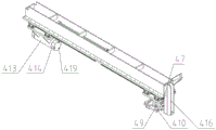
the main guide assembly 4 comprises a fixed frame 41, a main guide rail 42 is arranged at the bottom of the fixed frame 41 along the front-back direction, a front sliding seat 43 and a rear sliding seat 44 are arranged on the main guide rail 42, a guide bracket 45 is arranged on the front sliding seat 43, rod clamping rods 46 are hinged to the left side and the right side of the guide bracket 45, a rod clamping cylinder 47 is transversely arranged on the guide bracket 45, a piston rod end and a cylinder body end of the rod clamping cylinder 47 are respectively provided with a cylinder connector 48 and a first cylinder seat 49, and the cylinder connector 48 and the first cylinder seat 49 are respectively hinged to the front ends of the left rod clamping rod 46 and the right rod clamping rod 46 through a pin shaft 410;
a stop head 411 is arranged between the left and the right clamping rod rods 46;
guide cones 412 are arranged on the left side and the right side of the stop head 411;
a top rod 413 is arranged on the rear sliding seat 44, a top head 414 is arranged at the front end of the top rod 413, a second pressing ring 415 is arranged at the rear end of the top rod 413, and the piston rod end of the oil cylinder 7 is connected with the second pressing ring 415;
a bar blocking plate 416 is arranged on the front side of the fixed frame 41;
a guide cylinder 417 is arranged at the top of the fixed frame 41, and the front end of the guide cylinder 417 is connected with the front sliding seat 43 through a first cylinder connecting piece 418;
a plurality of positioning cones 419 are arranged on the front end face of the top head 414;
a transverse guide assembly 5 is arranged between the front beam assembly 2 and the oil cylinder mounting plate 3;
the transverse guide assembly 5 comprises a transverse guide seat 51, a transverse guide rail 52 is arranged at the top of the transverse guide seat 51, a positioning sliding plate 53 and a pressing sliding plate 54 are arranged on the transverse guide rail 52, a guide wheel mounting plate 55 is arranged on the positioning sliding plate 53, an upper group of guide wheels 56 and a lower group of guide wheels 56 are arranged on the guide wheel mounting plate 55, a pressing wheel mounting block 57 is arranged on the pressing sliding plate 54, a middle pressing wheel 58 is arranged on the pressing wheel mounting block 57, a supporting roller frame 59 is also arranged on the positioning sliding plate 53, the supporting roller frame 59 is positioned on the inner side of the guide wheel mounting plate 55, and a plurality of supporting rollers 510 are arranged on the supporting roller frame 59;
the upper and lower guide wheels 56 are arranged in a V shape, and the middle pressing wheel 58 is positioned between the upper and lower guide wheels 56;
a second cylinder block 511 is arranged on the transverse guide seat 51, a pressing cylinder 512 is arranged on the second cylinder block 511, the pressing cylinder 512 is positioned below the positioning sliding plate 53, and the piston rod end of the pressing cylinder 512 is connected with a pressing sliding plate 54 through a second cylinder connecting piece 513;
a rod moving mechanism 6 is arranged on one side of the main guide assembly 4;
the rod moving mechanism 6 comprises a rod moving rack 61, a rod moving guide rail 62 is arranged on the rod moving rack 61 along the front-back direction, a rod moving sliding plate 63 is arranged on the rod moving guide rail 62, a rod pushing rod 64 is arranged at the bottom of the rod moving sliding plate 63, a cylinder corner seat 65 is arranged behind the rod moving sliding plate 63, a rod moving cylinder 66 is arranged on the cylinder corner seat 65, and the piston rod end of the rod moving cylinder 66 is connected with the rod moving sliding plate 63;
an oil cylinder supporting component 8 is arranged behind the oil cylinder mounting plate 3, and the upper end of the oil cylinder supporting component 8 is abutted against the rear part of the oil cylinder 7;
a plurality of upright posts 9 are connected between the fixed plate 21 and the oil cylinder mounting plate 3;
and a rod feeding transition roller assembly 10 is arranged on one side of the front beam assembly 2.
In addition to the above embodiments, the present invention also includes other embodiments, and any technical solutions formed by equivalent transformation or equivalent replacement should fall within the scope of the claims of the present invention.
Claims (10)
1. The utility model provides an aluminium bar peeler which characterized in that: the hydraulic oil cylinder device comprises a rack (1), wherein a front beam assembly (2) is arranged on the rack (1), an oil cylinder mounting plate (3) is arranged behind the front beam assembly (2), a main guide assembly (4) is arranged between the front beam assembly (2) and the top of the oil cylinder mounting plate (3), and an oil cylinder (7) is arranged on the oil cylinder mounting plate (3); main guide subassembly (4) are including mount (41), mount (41) bottom is provided with main guide rail (42) along the fore-and-aft direction, be provided with preceding slide (43) and back slide (44) on main guide rail (42), be provided with clamping bar mechanism on preceding slide (43), be provided with ejector rod mechanism on back slide (44), hydro-cylinder (7) tailpiece of the piston rod end is connected with ejector rod mechanism, mount (41) top is provided with guide cylinder (417), guide cylinder (417) tailpiece of the piston rod end with be connected with preceding slide (43).
2. An aluminum bar peeling machine according to claim 1, characterized in that: the clamping rod mechanism comprises a guide support (45), clamping rod rods (46) are hinged to the left side and the right side of the guide support (45), a clamping rod cylinder (47) is transversely arranged on the guide support (45), a piston rod end and a cylinder body end of the clamping rod cylinder (47) are respectively provided with a cylinder joint (48) and a first cylinder seat (49), and the cylinder joint (48) and the first cylinder seat (49) are hinged to the front ends of the left clamping rod (46) and the right clamping rod (46) through a pin shaft (410).
3. An aluminum bar peeling machine according to claim 1, characterized in that: the ejector rod mechanism comprises an ejector rod (413), the front end of the ejector rod (413) is provided with an ejector head (414), the rear end of the ejector rod (413) is provided with a second pressing ring (415), and the piston rod end of the oil cylinder (7) is connected with the second pressing ring (415).
4. An aluminum bar peeling machine according to claim 2, characterized in that: a stop head (411) is arranged between the left and the right clamping rod rods (46), and guide cones (412) are arranged on the left and the right sides of the stop head (411).
5. An aluminum bar peeling machine according to claim 3, characterized in that: a plurality of positioning cones (419) are arranged on the front end face of the top head (414).
6. An aluminum bar peeling machine according to claim 1, characterized in that: the front beam assembly (2) comprises a fixing plate (21), a peeling knife (22) is arranged on the rear side of the fixing plate (21), a material returning ring (23) is arranged on the periphery of the peeling knife (22), a material returning cylinder (24) is arranged on the front side of the fixing plate (21), and the piston rod end of the material returning cylinder (24) is connected with the material returning ring (23).
7. An aluminum bar peeling machine according to claim 6, characterized in that: and a nozzle (27) is arranged on the material returning ring (23).
8. An aluminum bar peeling machine according to claim 1, characterized in that: a transverse guide assembly (5) is arranged between the front beam assembly (2) and the oil cylinder mounting plate (3); the transverse guide assembly (5) comprises a transverse guide seat (51), a transverse guide rail (52) is arranged at the top of the transverse guide seat (51), a positioning sliding plate (53) and a pressing sliding plate (54) are arranged on the transverse guide rail (52), a guide wheel mounting plate (55) is arranged on the positioning sliding plate (53), an upper guide wheel set and a lower guide wheel set (56) are arranged on the guide wheel mounting plate (55), a pressing wheel mounting block (57) is arranged on the pressing sliding plate (54), a middle pressing wheel (58) is arranged on the pressing wheel mounting block (57), a supporting wheel frame (59) is further arranged on the positioning sliding plate (53), the supporting wheel frame (59) is located on the inner side of the guide wheel mounting plate (55), and a plurality of supporting wheels (510) are arranged on the supporting wheel frame (59).
9. An aluminum bar peeling machine according to claim 8, characterized in that: the transverse guide seat (51) is provided with a second air cylinder seat (511), the second air cylinder seat (511) is provided with a pressing air cylinder (512), the pressing air cylinder (512) is located below the positioning sliding plate (53), and the piston rod end of the pressing air cylinder (512) is connected with the pressing sliding plate (54) through a second air cylinder connecting piece (513).
10. An aluminum bar peeling machine according to claim 1, characterized in that: a rod moving mechanism (6) is arranged on one side of the main guide assembly (4); move excellent mechanism (6) including moving excellent frame (61), it moves excellent guide rail (62) to be provided with along the fore-and-aft direction on excellent frame (61) to move, it moves excellent slide (63) to move to be provided with on excellent guide rail (62), it is provided with ejector pin pole (64) to move excellent slide (63) bottom, it is provided with cylinder angle seat (65) to move excellent slide (63) rear, be provided with on cylinder angle seat (65) and move excellent cylinder (66), it is connected with moving excellent slide (63) to move excellent cylinder (66) tailpiece of the piston rod.
Priority Applications (1)
| Application Number | Priority Date | Filing Date | Title |
|---|---|---|---|
| CN202011414951.5A CN112658399A (en) | 2020-12-07 | 2020-12-07 | Aluminum bar peeling machine |
Applications Claiming Priority (1)
| Application Number | Priority Date | Filing Date | Title |
|---|---|---|---|
| CN202011414951.5A CN112658399A (en) | 2020-12-07 | 2020-12-07 | Aluminum bar peeling machine |
Publications (1)
| Publication Number | Publication Date |
|---|---|
| CN112658399A true CN112658399A (en) | 2021-04-16 |
Family
ID=75401272
Family Applications (1)
| Application Number | Title | Priority Date | Filing Date |
|---|---|---|---|
| CN202011414951.5A Pending CN112658399A (en) | 2020-12-07 | 2020-12-07 | Aluminum bar peeling machine |
Country Status (1)
| Country | Link |
|---|---|
| CN (1) | CN112658399A (en) |
Cited By (1)
| Publication number | Priority date | Publication date | Assignee | Title |
|---|---|---|---|---|
| CN113523446A (en) * | 2021-08-02 | 2021-10-22 | 四川福蓉科技股份公司 | Aluminum bar peeling and falling device |
-
2020
- 2020-12-07 CN CN202011414951.5A patent/CN112658399A/en active Pending
Cited By (2)
| Publication number | Priority date | Publication date | Assignee | Title |
|---|---|---|---|---|
| CN113523446A (en) * | 2021-08-02 | 2021-10-22 | 四川福蓉科技股份公司 | Aluminum bar peeling and falling device |
| CN113523446B (en) * | 2021-08-02 | 2022-07-05 | 四川福蓉科技股份公司 | Aluminum bar peeling and falling device |
Similar Documents
| Publication | Publication Date | Title |
|---|---|---|
| CN107186284B (en) | Multi-station aluminum bar peeler | |
| CN109926810B (en) | Automatic extrusion angle sign indicating number mechanism of photovoltaic short frame | |
| CN209969266U (en) | Plate rolling machine | |
| CN108145249B (en) | A kind of groover of rosette | |
| CN112658399A (en) | Aluminum bar peeling machine | |
| CN214867761U (en) | Aluminum bar peeling machine | |
| CN210359504U (en) | But automatic discharge's panel is opened material and is cut device | |
| CN210632843U (en) | Bending and cutting device for steel structure production and processing | |
| CN210115359U (en) | Automobile exhaust mixing pipe forming equipment | |
| CN214264062U (en) | Plate shearing machine with automatic feeding structure | |
| CN215787047U (en) | Segmentation device for waste aluminum recovery rolled product | |
| CN214022595U (en) | Device is decided with calendering to solder strip | |
| CN206613944U (en) | A kind of automatic tube expander | |
| CN211275919U (en) | High-precision aluminum material extruding machine | |
| CN212703978U (en) | Full-automatic production line for stamping and shearing metal plates | |
| CN211072030U (en) | Aluminium alloy interrupt saw | |
| CN210908827U (en) | Photovoltaic short frame automatic extrusion angle code mechanism | |
| CN114558946A (en) | Stamping device for reinforced steel sheet and machining method thereof | |
| CN218340720U (en) | Steel plate right-angle bending structure | |
| CN107199374B (en) | Material returning assembly of aluminum bar peeler | |
| CN213826469U (en) | Automatic direct squaring extrusion device leads | |
| CN113198936B (en) | Stamping device is used in aluminium alloy ex-trusions processing | |
| CN215747640U (en) | Machine for automatically producing steel pipe nut pressing machine | |
| CN212634161U (en) | Automatic production system for steel bar welding | |
| CN219856119U (en) | Hydraulic press convenient for taking materials |
Legal Events
| Date | Code | Title | Description |
|---|---|---|---|
| PB01 | Publication | ||
| PB01 | Publication | ||
| SE01 | Entry into force of request for substantive examination | ||
| SE01 | Entry into force of request for substantive examination |