CN112647730A - Building skirting line glue filling equipment with measurement function - Google Patents
Building skirting line glue filling equipment with measurement function Download PDFInfo
- Publication number
- CN112647730A CN112647730A CN202110070316.8A CN202110070316A CN112647730A CN 112647730 A CN112647730 A CN 112647730A CN 202110070316 A CN202110070316 A CN 202110070316A CN 112647730 A CN112647730 A CN 112647730A
- Authority
- CN
- China
- Prior art keywords
- rotating shaft
- wall
- fixedly arranged
- bevel gear
- linkage
- Prior art date
- Legal status (The legal status is an assumption and is not a legal conclusion. Google has not performed a legal analysis and makes no representation as to the accuracy of the status listed.)
- Granted
Links
Images


Classifications
-
- E—FIXED CONSTRUCTIONS
- E04—BUILDING
- E04G—SCAFFOLDING; FORMS; SHUTTERING; BUILDING IMPLEMENTS OR AIDS, OR THEIR USE; HANDLING BUILDING MATERIALS ON THE SITE; REPAIRING, BREAKING-UP OR OTHER WORK ON EXISTING BUILDINGS
- E04G23/00—Working measures on existing buildings
- E04G23/02—Repairing, e.g. filling cracks; Restoring; Altering; Enlarging
- E04G23/0296—Repairing or restoring facades
Landscapes
- Engineering & Computer Science (AREA)
- Architecture (AREA)
- Chemical & Material Sciences (AREA)
- Chemical Kinetics & Catalysis (AREA)
- Electrochemistry (AREA)
- Mechanical Engineering (AREA)
- Civil Engineering (AREA)
- Structural Engineering (AREA)
- A Measuring Device Byusing Mechanical Method (AREA)
- Coating Apparatus (AREA)
Abstract
The invention discloses a building skirting line glue-filling device with a measuring function, which comprises a glue-filling device, wherein a working cavity is arranged in the glue-filling device, a lower wall through hole communicated with the outside is arranged on the inner wall of the lower side of the working cavity, a detection butt rod is arranged in the invention, a gap between a skirting line and a floor can be detected in the advancing process of the glue-filling device, and when the detection butt rod extends into the gap, a fifth bevel gear and a sixth bevel gear can be meshed and connected, so that a linkage push block has power for moving leftwards, and colloid in a glass rubber tube is extruded out through a gun barrel, thereby realizing automatic glue-filling work, saving time and labor, having higher efficiency, displaying the consumption condition of the glass rubber on a measuring display screen through the collision of a fixed rod and a hinged rotating rod, facilitating the timely replacement of the glass rubber by workers, recording the quantity of the rubber, and facilitating the price calculation of customers and decoration companies, reducing the occurrence of price dispute.
Description
Technical Field
The invention relates to the field of building construction equipment, in particular to building skirting line glue supplementing equipment with a measuring function.
Background
The existing floor with fine decoration is not very optimistic in decoration quality due to a plurality of reasons such as external wrapping. In particular, gaps are formed between a plurality of skirting lines and a floor, which not only affects the appearance, but also easily causes the phenomena of mildew and the like because foreign matters such as garbage and the like easily enter when residents live, and sometimes additional decoration companies are required to perform glue repairing work.
At present, when some renovation companies in charge of repair are in repair, a length measurement and statistics tool for glue filling is not provided, so that the problem of charging is often caused.
Disclosure of Invention
The invention aims to solve the technical problem of providing a building skirting line glue supplementing device with a measuring function, and the building skirting line glue supplementing device overcomes the problems.
The invention is realized by the following technical scheme.
The invention relates to a building skirting line glue-filling device with a measuring function, which comprises a glue-filling device, wherein a working cavity is arranged in the glue-filling device, a lower wall through hole communicated with the outside is arranged on the inner wall of the lower side of the working cavity, a detection control assembly is arranged in the working cavity, the detection control assembly comprises a vertical transverse plate which is fixedly arranged on the inner wall of the upper side of the working cavity and extends to the outside through the lower wall through hole, a detection butt-joint rod which is arranged at the lower end of the vertical transverse plate and can be contacted with the contact part of a skirting line and the ground, a linkage hole which is arranged in the vertical transverse plate and penetrates left and right, a spring bracket which is in sliding connection with the inner wall of the rear side of the linkage hole, a connecting spring which is connected between the spring bracket and the inner wall of the lower side of the linkage hole, a linkage slide block which is in sliding connection with the left end of the, still be equipped with in the working chamber and mend and glue measuring subassembly, mend glue measuring subassembly including set firmly in the barrel through-hole of working chamber rear side inner wall is located just upside open-ended glass glues the rifle in the barrel through-hole, locates glass glues rifle left side inner wall and with the communicating barrel through-hole of working chamber can place the glass rubber tube in glass glues the rifle, set firmly in the glass rubber tube left end just passes through the barrel through-hole extends to barrel in the working chamber locates glass glues rifle right side inner wall and with the communicating push rod spout of working chamber, sliding connection in the linkage push rod that extends about the push rod spout sets firmly in the linkage ejector pad of linkage push rod left end, still be equipped with power transmission assembly in the working chamber.
The detection control assembly further comprises an arc-shaped support fixedly arranged at the right end of the spring support, a first rotating shaft rotatably connected to the lower end of the arc-shaped support, a driving friction wheel fixedly arranged on the first rotating shaft, a second rotating shaft rotatably connected to the inner wall of the rear side of the working cavity, and a driven friction wheel fixedly arranged on the second rotating shaft and capable of being in friction connection with the driving friction wheel.
Wherein, the glue-filling measuring component also comprises a fixed support plate fixedly arranged at the right end of the linkage push rod, a fixed block is fixedly arranged on the inner wall of the rear side of the working cavity, a linkage spring is connected between the fixed block and the fixed support plate, the inner wall of the rear side of the working cavity is rotatably connected with a third rotating shaft, a linkage friction wheel which is in friction connection with the lower end of the linkage push rod is fixedly arranged on the third rotating shaft, a ratchet wheel is fixedly arranged on the third rotating shaft, a hinged pawl which can be abutted against the pawl on the ratchet wheel is hinged on the inner wall of the rear side of the working cavity, a telescopic spring is connected between the hinged pawl and the fixed block, a movable limiting block which can slide left and right and is positioned at the lower side of the hinged pawl is arranged on the inner wall of the rear side of the working cavity, the movable limiting block can be abutted against the, and a power friction wheel in friction connection with the linkage friction wheel is fixedly arranged on the fourth rotating shaft.
Beneficially, set firmly in the fourth pivot and be located the fixed runner of power friction pulley front side, set firmly the dead lever on the fixed runner, working chamber rear side inner wall set firmly be located the detection piece support of fixed casing downside, it detects the piece to detect piece support lower extreme and has set firmly the signal detection piece, working chamber rear side inner wall articulates to be located detect piece support downside and can with the dead lever and the articulated bull stick of signal detection piece butt, articulated bull stick with be connected with the bull stick spring between the detection piece support, working chamber rear side inner wall set firmly be located the measurement display screen of fixed casing upside, just the measurement display screen with signal detection piece electric connection.
Wherein, the power transmission component comprises two fifth rotating shafts which are rotationally connected with the rear inner wall of the working cavity in a bilateral symmetry way and extend forwards to the front inner wall of the working cavity, each fifth rotating shaft is fixedly provided with two wheels which are contacted with the ground through the lower wall through hole in a front-back symmetry way, the fifth rotating shaft at the right side is fixedly provided with a first bevel gear positioned between the two wheels, the inner wall at the right side of the working cavity is fixedly provided with a horizontal transverse plate which extends leftwards, the horizontal transverse plate is rotationally connected with a sixth rotating shaft which extends upwards and downwards and is connected with the first rotating shaft in a spline connection way, the sixth rotating shaft positioned at the lower side of the horizontal transverse plate is fixedly provided with a second bevel gear meshed with the first bevel gear, the sixth rotating shaft positioned at the upper side of the horizontal transverse plate is fixedly provided with a third bevel gear, and the upper end of the horizontal, a seventh rotating shaft which extends leftwards and rightwards is rotatably connected to the vertical support, a fourth bevel gear which is meshed with the third bevel gear is fixedly arranged on the seventh rotating shaft which is positioned on the right side of the vertical support, a driven sliding block which can slide leftwards and rightwards and is positioned on the right side of the vertical support is arranged at the upper end of the horizontal transverse plate, a reset spring is connected between the driven sliding block and the vertical support, a rotating shaft through hole which is communicated leftwards and rightwards is arranged on the driven sliding block, a connecting rod is fixedly arranged at the left end of the driven sliding block, a suspension support is fixedly arranged at the lower end of the connecting rod, an eighth rotating shaft which extends leftwards and rightwards and is connected with the seventh rotating shaft through a spline is rotatably connected to the suspension support, a fifth bevel gear is fixedly arranged on the eighth rotating shaft which is positioned on the left side of the suspension support, and a sixth bevel gear which is positioned on the front side of the fixed rotating, the second pivot on set firmly be located driven friction pulley rear side and can with the butt runner of driven slider butt, the linkage branch has set firmly on the butt runner, linkage branch right-hand member has set firmly the arc fixed block, be equipped with upside open-ended arc chamber in the arc fixed block, working chamber right side inner wall has set firmly the fixed bolster, the fixed bolster lower extreme has set firmly the arc slider, just the arc slider with arc intracavity wall sliding connection, the arc slider with be connected with the intracavity spring between the arc chamber downside inner wall, working chamber right side inner wall has set firmly the motor, motor left end power is connected with the ninth pivot, set firmly in the ninth pivot with the seventh bevel gear that third bevel gear meshing is connected.
The invention has the beneficial effects that: the invention is provided with the detection butt joint rod, can detect the gap between the skirting line and the floor in the advancing process of the glue supplementing equipment, and can ensure that the linkage push block has power for moving leftwards by meshing and connecting the fifth bevel gear and the sixth bevel gear when the detection butt joint rod extends into the gap, thereby extruding glue in the glass glue tube through the gun barrel, realizing automatic glue supplementing work, saving time and labor, having higher efficiency, displaying the consumption condition of the glass glue on the measurement display screen through the collision of the fixed rod and the hinged rotating rod, facilitating the timely replacement of the glass glue by workers, also displaying the quantity of the glue for recording, facilitating the price calculation of customers and decoration companies and reducing the occurrence of price disputes.
Drawings
In order to more clearly illustrate the embodiments of the invention or the technical solutions in the prior art, the drawings used in the description of the embodiments or the prior art will be briefly described below, and it is obvious that the drawings in the following description are only some embodiments of the invention, and it is obvious for those skilled in the art that other drawings can be obtained based on these drawings without creative efforts.
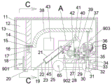
FIG. 1 is a schematic structural diagram of an embodiment of the present invention;
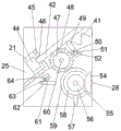
FIG. 2 is a schematic enlarged view of the structure of "A" of FIG. 1;
FIG. 3 is a schematic enlarged view of the structure of "B" of FIG. 1;
FIG. 4 is a schematic view of the structure in the direction "C-C" of FIG. 1.
Detailed Description
The invention will now be described in detail with reference to fig. 1-4, wherein for ease of description the orientations described hereinafter are now defined as follows: the up, down, left, right, and front-back directions described below correspond to the up, down, left, right, and front-back directions in the projection relationship of fig. 1 itself.
The building skirting line glue supplementing device with the measurement function, which is described in conjunction with the attached drawings 1-4, comprises a glue supplementing device 11, wherein a working cavity 12 is arranged in the glue supplementing device 11, a lower wall through hole 19 communicated with the outside is arranged on the inner wall of the lower side of the working cavity 12, a detection control assembly 901 is arranged in the working cavity 12, the detection control assembly 901 comprises a vertical transverse plate 13 which is fixedly arranged on the inner wall of the upper side of the working cavity 12 and extends to the outside through the lower wall through hole 19, a detection butt rod 20 which is arranged at the lower end of the vertical transverse plate 13 and can be contacted with the contact part of a skirting line and the ground, a linkage hole 14 which is arranged in the vertical transverse plate 13 and penetrates left and right, a spring support 15 which is slidably connected with the inner wall of the rear side of the linkage hole 14, a connecting spring 17 which is connected between the spring support 15 and the inner wall of the lower side of the linkage hole 14, and a linkage slide block, a hinge rod 18 hinged between the linkage sliding block 16 and the detection butt rod 20, when there is a gap between the skirting line and the ground, under the action of a connecting spring 17, the detection butt rod 20 extends into the gap, the working chamber 12 is further provided with a glue filling measuring component 902, the glue filling measuring component 902 comprises a barrel through hole 23 fixedly arranged on the inner wall of the rear side of the working chamber 12, a glass glue gun 21 arranged in the barrel through hole 23 and having an opening at the upper side, a barrel through hole 23 arranged on the inner wall of the left side of the glass glue gun 21 and communicated with the working chamber 12, a glass glue tube 25 capable of being placed in the glass glue gun 21, a barrel 22 fixedly arranged on the left end of the glass glue tube 25 and extending into the working chamber 12 through the barrel through hole 23, a push rod chute 46 arranged on the inner wall of the right side of the glass glue gun 21 and communicated with the working chamber 12, and a push rod 42 slidably connected to the push rod linkage chute 46 and extending left and right, the linkage push block 44 is fixedly arranged at the left end of the linkage push rod 42, the linkage push block 44 moves leftwards, so that glass cement in the glass cement pipe 25 can be extruded to a skirting line gap, and a power transmission component 903 for realizing linkage between components and advancing of the cement supplementing device 11 is further arranged in the working cavity 12.
According to an embodiment, the detection control assembly 901 is described in detail below, the detection control assembly 901 further includes an arc support 38 fixed to the right end of the spring support 15, a first rotating shaft 37 rotatably connected to the lower end of the arc support 38, a driving friction wheel 76 fixed to the first rotating shaft 37, a second rotating shaft 69 rotatably connected to the inner wall of the rear side of the working chamber 12, and a driven friction wheel 68 fixed to the second rotating shaft 69 and capable of being in friction connection with the driving friction wheel 76, and the driving friction wheel 76 and the driven friction wheel 68 are controlled to be in friction connection by the upward movement of the arc support 38.
According to the embodiment, the following detailed description will be made on the glue filling measuring assembly 902, the glue filling measuring assembly 902 further includes a fixing support plate 40 fixedly disposed at the right end of the linkage push rod 42, a fixing block 49 is fixedly disposed on the inner wall of the rear side of the working chamber 12, a linkage spring 41 is connected between the fixing block 49 and the fixing support plate 40, the inner wall of the rear side of the working chamber 12 is rotatably connected with a third rotating shaft 60, a linkage friction wheel 48 frictionally connected with the lower end of the linkage push rod 42 is fixedly disposed on the third rotating shaft 60, a ratchet wheel 47 is fixedly disposed on the third rotating shaft 60, a hinge pawl 51 capable of abutting against a pawl on the ratchet wheel 47 is hinged to the inner wall of the rear side of the working chamber 12, an extension spring 50 is connected between the hinge pawl 51 and the fixing block 49, a movable limiting block 52 capable of sliding left and right and disposed on the lower side of the hinge pawl 51, and the movable limiting block 52 can be abutted against the movable limiting block 52 of the hinged pawl 51, the inner wall of the rear side of the working cavity 12 is rotatably connected with a fourth rotating shaft 55, and a power friction wheel 59 in friction connection with the linkage friction wheel 48 is fixedly arranged on the fourth rotating shaft 55.
Beneficially, a fixed rotating wheel 58 located in front of the power friction wheel 59 is fixedly arranged on the fourth rotating shaft 55, a fixed rod 57 is fixedly arranged on the fixed rotating wheel 58, a detection block support 64 located on the lower side of the fixed shell 45 is fixedly arranged on the inner wall of the rear side of the working chamber 12, a signal detection block 61 is fixedly arranged at the lower end of the detection block support 64, a hinged rotating rod 62 located on the lower side of the detection block support 64 and capable of abutting against the fixed rod 57 and the signal detection block 61 is hinged to the inner wall of the rear side of the working chamber 12, a rotating rod spring 63 is connected between the hinged rotating rod 62 and the detection block support 64, a measurement display screen 43 located on the upper side of the fixed shell 45 is fixedly arranged on the inner wall of the rear side of the working chamber 12, and the measurement display screen 43 is electrically connected with the signal detection block 61.
According to the embodiment, the power transmission assembly 903 is described in detail below, the power transmission assembly 903 includes two fifth rotating shafts 65 which are connected to the inner wall of the rear side of the working chamber 12 in a left-right symmetric manner and extend forward to the inner wall of the front side of the working chamber 12, two wheels 31 which contact the ground through the lower wall through hole 19 are symmetrically and fixedly arranged on each of the fifth rotating shafts 65, a first bevel gear 30 is fixedly arranged on the fifth rotating shaft 65 on the right side between the two wheels 31, a horizontal transverse plate 34 which extends leftward is fixedly arranged on the inner wall of the right side of the working chamber 12, a sixth rotating shaft 33 which extends up and down and is in splined connection with the first rotating shaft 37 is rotatably connected to the horizontal transverse plate 34, a gear 32 which is engaged with the first bevel gear 30 is fixedly arranged on the sixth rotating shaft 33 on the lower side of the horizontal transverse plate 34, a third bevel gear 80 is fixedly arranged on the sixth rotating shaft 33 on the upper side of the horizontal transverse plate 34, a vertical bracket 29 is fixedly arranged at the upper end of the horizontal transverse plate 34, a seventh rotating shaft 78 extending left and right is rotatably connected to the vertical bracket 29, a fourth bevel gear 77 engaged with the third bevel gear 80 is fixedly arranged on the seventh rotating shaft 78 positioned at the right side of the vertical bracket 29, a driven slider 66 capable of sliding left and right and positioned at the right side of the vertical bracket 29 is arranged at the upper end of the horizontal transverse plate 34, a return spring 35 is connected between the driven slider 66 and the vertical bracket 29, a left and right through rotating shaft through hole 79 is arranged on the driven slider 66, the seventh rotating shaft 78 extends right through the rotating shaft through hole 79, a connecting rod 39 is fixedly arranged at the left end of the driven slider 66, a suspension bracket 27 is fixedly arranged at the lower end of the connecting rod 39, and an eighth rotating shaft 28 extending left and right and connected with the seventh rotating shaft 78 through splines is rotatably connected to the suspension bracket 27, a fifth bevel gear 54 is fixedly arranged on the eighth rotating shaft 28 positioned at the left side of the hanging bracket 27, a sixth bevel gear 56 which is positioned at the front side of the fixed rotating wheel 58 and can be meshed and connected with the fifth bevel gear 54 is fixedly arranged on the fourth rotating shaft 55, an abutting rotating wheel 67 which is positioned at the rear side of the driven friction wheel 68 and can be abutted against the driven sliding block 66 is fixedly arranged on the second rotating shaft 69, a linkage supporting rod 75 is fixedly arranged on the abutting rotating wheel 67, an arc-shaped fixed block 72 is fixedly arranged at the right end of the linkage supporting rod 75, an arc-shaped cavity 73 with an opening at the upper side is arranged in the arc-shaped fixed block 72, a fixed bracket 36 is fixedly arranged on the inner wall at the right side of the working cavity 12, an arc-shaped sliding block 70 is fixedly arranged at the lower end of the fixed bracket 36, the arc-shaped sliding block 70 is slidably connected with the inner wall of, a motor 81 is fixedly arranged on the inner wall of the right side of the working cavity 12, a ninth rotating shaft 82 is dynamically connected to the left end of the motor 81, and a seventh bevel gear 83 meshed with the third bevel gear 80 is fixedly arranged on the ninth rotating shaft 82.
In the initial state, the fifth bevel gear 54 is not meshed with the sixth bevel gear 56, the linkage push block 44 is located at the right limit position, and the spring support 15 is located at the upper limit position.
Application method
During operation, the glue supplementing device 11 is moved, so that the detection butting rod 20 is attached to a contact position between a skirting line and the ground, the detection butting rod 20 moves forwards, the detection butting rod 20 moving forwards drives the spring support 15 to move downwards through the hinge rod 18 and the linkage sliding block 16, the connecting spring 17 accumulates elastic potential energy, and the spring support 15 moving upwards drives the driving friction wheel 76 to be not in friction connection with the driven friction wheel 68 through the arc-shaped support 38 and the first rotating shaft 37;
at this time, the motor 81 is started, so that the ninth rotating shaft 82 rotates, the rotating ninth rotating shaft 82 drives the third bevel gear 80 to rotate, the rotating third bevel gear 80 sequentially passes through the fourth bevel gear 77, the seventh rotating shaft 78 and the eighth rotating shaft 28 to drive the fifth bevel gear 54 to rotate, the rotating third bevel gear 80 drives the sixth rotating shaft 33 to rotate, the rotating sixth rotating shaft 33 drives the driving friction wheel 76 to rotate through the first rotating shaft 37, the rotating sixth rotating shaft 33 drives the right wheel 31 to rotate counterclockwise through the second bevel gear 32, the first bevel gear 30 and the right fifth rotating shaft 65, and thus the glue replenishing device 11 advances leftward;
when the detection butting rod 20 moves to the gap between the skirting line and the ground, the connecting spring 17 releases elastic potential energy and drives the spring support 15 to move upwards, the upward moving spring support 15 drives the detection butting rod 20 to enter the gap through the linkage sliding block 16 and the hinge rod 18, the upward moving spring support 15 drives the driving friction wheel 76 and the driven friction wheel 68 to be in friction connection through the arc support 38 and the first rotating shaft 37, so that the rotating driving friction wheel 76 drives the butting rotating wheel 67 to rotate anticlockwise through the driven friction wheel 68 and the second rotating shaft 69, the rotating butting rotating wheel 67 and the driven sliding block 66 butt against and drive the driven sliding block 66 to move leftwards along with the rotation of the butting rotating wheel 67, the rotating butting rotating wheel 67 drives the arc fixing block 72 to rotate through the linkage supporting rod 75, the spring 74 in the cavity accumulates elastic potential energy, and when the arc fixing block 72 and the fixing support 36 butt against each other, the driven friction wheel 68 is not driven to rotate any more by the friction of the driving friction wheel 76 on the driven friction wheel 68, the driven slide block 66 moving leftwards drives the fifth bevel gear 54 and the sixth bevel gear 56 to be meshed and connected through the connecting rod 39, the suspension bracket 27 and the eighth rotating shaft 28, so that the rotating fifth bevel gear 54 drives the fourth rotating shaft 55 to rotate clockwise through the sixth bevel gear 56, the clockwise rotating fourth rotating shaft 55 drives the linkage push rod 42 and the fixed support plate 40 to move leftwards through the power friction wheel 59 and the linkage friction wheel 48, the linkage spring 41 stores elastic potential energy, the linkage push rod 42 moving leftwards enables the linkage push block 44 to push glass cement in the glass cement pipe 25 to be extruded to a gap through the gun barrel 22, the cement supplementing work is completed, and in the rotating process of the abutting rotating wheel 67, the time delay function can be realized by utilizing the time interval when the abutting rotating wheel 67 and the driven slide block 66 abut against, that is, when the detecting abutting rod 20 on the left side of the barrel 22 is located at the gap, the barrel 22 will not immediately discharge glue, when the left end of the barrel 22 moves to the gap, the abutting rotary wheel 67 will abut against the driven slide block 66 and drive the driven slide block 66 to move leftwards, when the barrel 22 and the gap are no longer located at the gap, the driven slide block 66 will not reset rightwards, and the barrel 22 can perform glue filling work on the rest part of the gap, in the movement of the above-mentioned linkage push rod 42, under the limitation of the hinge pawl 51 and the movable limit block 52, the linkage push rod 42 will not reset rightwards, the rotating fourth rotary shaft 55 drives the fixed rod 57 to rotate through the fixed rotary wheel 58, when the fixed rod 57 collides with the hinge rotary rod 62 and drives the hinge rotary rod 62 to rotate, the signal detecting block 61 can record the number of rotations of the hinge rotary rod 62, and when the hinge rotary rod 62 rotates each time, the measurement display screen 43 records and displays data, so that workers can conveniently check the consumption condition of the glass cement in the glass cement tube 25;
when the detection abutting rod 20 is no longer positioned at the gap along with the advancing of the glue supplementing device 11, the detection abutting rod 20 moves backwards again, the abutting rotating wheel 67 rotates reversely and resets under the action of the cavity spring 74, and the fifth bevel gear 54 is no longer in meshing connection with the sixth bevel gear 56 under the action of the resetting spring 35;
when the glass rubber tube 25 needs to be used up and needs to be replaced, the motor 81 is turned off, the movable limiting block 52 is manually shifted rightwards, the movable limiting block 52 does not limit the hinged pawl 51 any more, the linkage spring 41 releases elastic potential energy and drives the linkage push rod 42 to reset rightwards through the fixed support plate 40 and the linkage push rod 42, a worker can take out the used glass rubber tube 25 and install a new glass rubber tube 25 at the moment, and after the glass rubber tube 25 is installed, the movable limiting block 52 resets leftwards, and the device recovers to an initial state.
The above embodiments are merely illustrative of the technical ideas and features of the present invention, and the purpose thereof is to enable those skilled in the art to understand the contents of the present invention and implement the present invention, and not to limit the protection scope of the present invention. All equivalent changes and modifications made according to the spirit of the present invention should be covered within the protection scope of the present invention.
Claims (5)
1. The utility model provides a building skirting line mends gluey equipment with measurement function, includes to mend gluey equipment, be equipped with the working chamber in the benefit gluey equipment, working chamber downside inner wall is equipped with and external communicating lower wall through-hole, its characterized in that:
the detection control assembly is arranged in the working cavity and comprises a vertical transverse plate, a detection butt rod, a linkage hole, a spring support, a connecting spring, a linkage slide block and a hinge rod, wherein the vertical transverse plate is fixedly arranged on the inner wall of the upper side of the working cavity and extends to the outside through the lower wall through hole;
still be equipped with in the working chamber and mend and glue measuring subassembly, mend glue measuring subassembly including set firmly in the barrel through-hole of working chamber rear side inner wall is located just upside open-ended glass glues the rifle in the barrel through-hole, locates glass glues rifle left side inner wall and with the communicating barrel through-hole of working chamber can place the glass rubber tube in glass glues the rifle, set firmly in the glass rubber tube left end just passes through the barrel through-hole extends to barrel in the working chamber locates glass glues rifle right side inner wall and with the communicating push rod spout of working chamber, sliding connection in the linkage push rod that extends about the push rod spout sets firmly in the linkage ejector pad of linkage push rod left end, still be equipped with power transmission assembly in the working chamber.
2. The building skirting line glue filling equipment with the measurement function of claim 1, characterized in that: the detection control assembly further comprises an arc-shaped support fixedly arranged at the right end of the spring support, a first rotating shaft rotatably connected to the lower end of the arc-shaped support, a driving friction wheel fixedly arranged on the first rotating shaft, a second rotating shaft rotatably connected to the inner wall of the rear side of the working cavity, and a driven friction wheel fixedly arranged on the second rotating shaft and capable of being in friction connection with the driving friction wheel.
3. The building skirting line glue filling equipment with the measurement function of claim 1, characterized in that: the glue-supplementing measuring component also comprises a fixed support plate fixedly arranged at the right end of the linkage push rod, a fixed block is fixedly arranged on the inner wall of the rear side of the working cavity, a linkage spring is connected between the fixed block and the fixed support plate, the inner wall of the rear side of the working cavity is rotatably connected with a third rotating shaft, a linkage friction wheel in friction connection with the lower end of the linkage push rod is fixedly arranged on the third rotating shaft, a ratchet wheel is fixedly arranged on the third rotating shaft, a hinged pawl capable of being abutted against the pawl on the ratchet wheel is hinged to the inner wall of the rear side of the working cavity, a telescopic spring is connected between the hinged pawl and the fixed block, a movable limiting block capable of sliding left and right and positioned at the lower side of the hinged pawl is arranged on the inner wall of the rear side of the working cavity, the movable limiting block can be abutted against the hinged pawl, and a power friction wheel in friction connection with the linkage friction wheel is fixedly arranged on the fourth rotating shaft.
4. The building skirting line glue filling equipment with the measurement function of claim 3, characterized in that: the fixed runner that is located the power friction wheel front side has set firmly in the fourth pivot, the dead lever has set firmly on the fixed runner, working chamber rear side inner wall set firmly be located the detection piece support of fixed casing downside, it sets firmly the signal detection piece to detect piece support lower extreme, working chamber rear side inner wall articulates to be located detect piece support downside and can with the dead lever and the articulated bull stick of signal detection piece butt, articulated bull stick with be connected with the bull stick spring between the detection piece support, working chamber rear side inner wall set firmly be located the measurement display screen of fixed casing upside, just the measurement display screen with signal detection piece electric connection.
5. The building skirting line glue filling equipment with the measurement function of claim 1, characterized in that: the power transmission assembly comprises two fifth rotating shafts which are bilaterally symmetrically and rotationally connected to the inner wall of the rear side of the working cavity and extend forwards to the inner wall of the front side of the working cavity, two wheels which are contacted with the ground through the lower wall through hole are symmetrically and fixedly arranged on each fifth rotating shaft in a front-back manner, a first bevel gear positioned between the two wheels is fixedly arranged on the fifth rotating shaft on the right side, a horizontal transverse plate which extends leftwards is fixedly arranged on the inner wall of the right side of the working cavity, a sixth rotating shaft which extends vertically and is in spline connection with the first rotating shaft is rotationally connected to the horizontal transverse plate, a second bevel gear meshed with the first bevel gear is fixedly arranged on the sixth rotating shaft positioned on the lower side of the horizontal transverse plate, a third bevel gear is fixedly arranged on the sixth rotating shaft positioned on the upper side of the horizontal transverse plate, a vertical support is fixedly arranged at the upper end of the horizontal transverse plate, and a, a fourth bevel gear meshed with the third bevel gear is fixedly arranged on the seventh rotating shaft positioned on the right side of the vertical support, a driven sliding block capable of sliding left and right and positioned on the right side of the vertical support is arranged at the upper end of the horizontal transverse plate, a reset spring is connected between the driven sliding block and the vertical support, a left-right through rotating shaft through hole is formed in the driven sliding block, the seventh rotating shaft extends rightwards through the rotating shaft through hole, a connecting rod is fixedly arranged at the left end of the driven sliding block, a suspension support is fixedly arranged at the lower end of the connecting rod, an eighth rotating shaft extending left and right and connected with the seventh rotating shaft through a spline is rotatably connected to the suspension support, a fifth bevel gear is fixedly arranged on the eighth rotating shaft positioned on the left side of the suspension support, and a sixth bevel gear positioned in front of the fixed rotating wheel and meshed with the fifth bevel gear is fixedly arranged on the, the second pivot on set firmly be located driven friction pulley rear side and can with the butt runner of driven slider butt, the linkage branch has set firmly on the butt runner, linkage branch right-hand member has set firmly the arc fixed block, be equipped with upside open-ended arc chamber in the arc fixed block, working chamber right side inner wall has set firmly the fixed bolster, the fixed bolster lower extreme has set firmly the arc slider, just the arc slider with arc intracavity wall sliding connection, the arc slider with be connected with the intracavity spring between the arc chamber downside inner wall, working chamber right side inner wall has set firmly the motor, motor left end power is connected with the ninth pivot, set firmly in the ninth pivot with the seventh bevel gear that third bevel gear meshing is connected.
Priority Applications (1)
| Application Number | Priority Date | Filing Date | Title |
|---|---|---|---|
| CN202110070316.8A CN112647730B (en) | 2021-01-19 | 2021-01-19 | Building skirting line glue supplementing equipment with measurement function |
Applications Claiming Priority (1)
| Application Number | Priority Date | Filing Date | Title |
|---|---|---|---|
| CN202110070316.8A CN112647730B (en) | 2021-01-19 | 2021-01-19 | Building skirting line glue supplementing equipment with measurement function |
Publications (2)
| Publication Number | Publication Date |
|---|---|
| CN112647730A true CN112647730A (en) | 2021-04-13 |
| CN112647730B CN112647730B (en) | 2023-06-13 |
Family
ID=75370673
Family Applications (1)
| Application Number | Title | Priority Date | Filing Date |
|---|---|---|---|
| CN202110070316.8A Active CN112647730B (en) | 2021-01-19 | 2021-01-19 | Building skirting line glue supplementing equipment with measurement function |
Country Status (1)
| Country | Link |
|---|---|
| CN (1) | CN112647730B (en) |
Citations (20)
| Publication number | Priority date | Publication date | Assignee | Title |
|---|---|---|---|---|
| GB8719330D0 (en) * | 1987-07-03 | 1987-09-23 | Konishi Co Ltd | Injecting adhesives |
| EP0457963A2 (en) * | 1990-05-22 | 1991-11-27 | SCHOTTEN & HANSEN GmbH | Device for applying glue to grooves and hairline cracks in woods, particularly for gluing loose knots in planks |
| WO2003006178A1 (en) * | 2001-07-12 | 2003-01-23 | Vkr Holding A/S | Method and arrangement for applying a viscous material with means for regulating the material supply |
| CN102053062A (en) * | 2010-12-08 | 2011-05-11 | 中国建筑科学研究院 | Structural adhesive on-site detection method and device |
| CN204730891U (en) * | 2015-06-17 | 2015-10-28 | 厦门优路达汽车科技股份有限公司 | Vapour-pressure type glue sprayer flowmeter, vapour-pressure type glue sprayer and doughnut glue spraying equipment |
| CN206083015U (en) * | 2016-09-14 | 2017-04-12 | 广州福耀玻璃有限公司 | Glue squeezing apparatus |
| CN107178217A (en) * | 2017-07-25 | 2017-09-19 | 江苏省苏中建设集团股份有限公司 | One kind repaiies hollowing glue rifle |
| CN206844602U (en) * | 2017-06-12 | 2018-01-05 | 安阳建工(集团)有限责任公司 | A kind of track-type multi-function gluing device |
| CN109057273A (en) * | 2018-09-11 | 2018-12-21 | 洛阳理工学院 | A kind of automatic Mei Feng robot and its application method |
| CN109697497A (en) * | 2017-10-22 | 2019-04-30 | 赵香宇 | A kind of sealing-tape machine counts drive system automatically |
| CN110158986A (en) * | 2019-06-10 | 2019-08-23 | 中鼎国际工程有限责任公司 | A kind of construction processes wall crazing restorative procedure and equipment |
| CN110461481A (en) * | 2018-02-07 | 2019-11-15 | 深圳市大疆百旺科技有限公司 | It is a kind of for glue component and its gluing equipment of application |
| CN110961314A (en) * | 2019-12-19 | 2020-04-07 | 广东博智林机器人有限公司 | Glue applying robot and glue applying device thereof |
| CN210828224U (en) * | 2019-07-08 | 2020-06-23 | 许钱江 | Automatic seam beautifying machine for ceramic tiles |
| CN111636657A (en) * | 2020-07-01 | 2020-09-08 | 金华惺忪科技有限公司 | Automatic seam beautifying device for floor tiles |
| CN111946031A (en) * | 2020-08-11 | 2020-11-17 | 台州八鑫工贸股份有限公司 | Walking trolley of automatic seam beautifying machine |
| CN111980374A (en) * | 2020-09-08 | 2020-11-24 | 福州台江爱企时电子科技有限公司 | Accurate beautiful seam equipment of ceramic tile for fitment |
| CN112031454A (en) * | 2020-09-08 | 2020-12-04 | 上海城建职业学院 | Automatic gluing machine for wall joints of prefabricated buildings |
| CN112127601A (en) * | 2020-09-29 | 2020-12-25 | 上海富艺幕墙工程有限公司 | Automatic sealant coating device for unit curtain wall and assembling system |
| CN112227163A (en) * | 2020-10-13 | 2021-01-15 | 广州新程北斗信息科技有限公司 | Internet of vehicles road detection equipment |
-
2021
- 2021-01-19 CN CN202110070316.8A patent/CN112647730B/en active Active
Patent Citations (20)
| Publication number | Priority date | Publication date | Assignee | Title |
|---|---|---|---|---|
| GB8719330D0 (en) * | 1987-07-03 | 1987-09-23 | Konishi Co Ltd | Injecting adhesives |
| EP0457963A2 (en) * | 1990-05-22 | 1991-11-27 | SCHOTTEN & HANSEN GmbH | Device for applying glue to grooves and hairline cracks in woods, particularly for gluing loose knots in planks |
| WO2003006178A1 (en) * | 2001-07-12 | 2003-01-23 | Vkr Holding A/S | Method and arrangement for applying a viscous material with means for regulating the material supply |
| CN102053062A (en) * | 2010-12-08 | 2011-05-11 | 中国建筑科学研究院 | Structural adhesive on-site detection method and device |
| CN204730891U (en) * | 2015-06-17 | 2015-10-28 | 厦门优路达汽车科技股份有限公司 | Vapour-pressure type glue sprayer flowmeter, vapour-pressure type glue sprayer and doughnut glue spraying equipment |
| CN206083015U (en) * | 2016-09-14 | 2017-04-12 | 广州福耀玻璃有限公司 | Glue squeezing apparatus |
| CN206844602U (en) * | 2017-06-12 | 2018-01-05 | 安阳建工(集团)有限责任公司 | A kind of track-type multi-function gluing device |
| CN107178217A (en) * | 2017-07-25 | 2017-09-19 | 江苏省苏中建设集团股份有限公司 | One kind repaiies hollowing glue rifle |
| CN109697497A (en) * | 2017-10-22 | 2019-04-30 | 赵香宇 | A kind of sealing-tape machine counts drive system automatically |
| CN110461481A (en) * | 2018-02-07 | 2019-11-15 | 深圳市大疆百旺科技有限公司 | It is a kind of for glue component and its gluing equipment of application |
| CN109057273A (en) * | 2018-09-11 | 2018-12-21 | 洛阳理工学院 | A kind of automatic Mei Feng robot and its application method |
| CN110158986A (en) * | 2019-06-10 | 2019-08-23 | 中鼎国际工程有限责任公司 | A kind of construction processes wall crazing restorative procedure and equipment |
| CN210828224U (en) * | 2019-07-08 | 2020-06-23 | 许钱江 | Automatic seam beautifying machine for ceramic tiles |
| CN110961314A (en) * | 2019-12-19 | 2020-04-07 | 广东博智林机器人有限公司 | Glue applying robot and glue applying device thereof |
| CN111636657A (en) * | 2020-07-01 | 2020-09-08 | 金华惺忪科技有限公司 | Automatic seam beautifying device for floor tiles |
| CN111946031A (en) * | 2020-08-11 | 2020-11-17 | 台州八鑫工贸股份有限公司 | Walking trolley of automatic seam beautifying machine |
| CN111980374A (en) * | 2020-09-08 | 2020-11-24 | 福州台江爱企时电子科技有限公司 | Accurate beautiful seam equipment of ceramic tile for fitment |
| CN112031454A (en) * | 2020-09-08 | 2020-12-04 | 上海城建职业学院 | Automatic gluing machine for wall joints of prefabricated buildings |
| CN112127601A (en) * | 2020-09-29 | 2020-12-25 | 上海富艺幕墙工程有限公司 | Automatic sealant coating device for unit curtain wall and assembling system |
| CN112227163A (en) * | 2020-10-13 | 2021-01-15 | 广州新程北斗信息科技有限公司 | Internet of vehicles road detection equipment |
Non-Patent Citations (1)
| Title |
|---|
| 张文波等: "楼层局部渗漏与防治", 《工程质量》 * |
Also Published As
| Publication number | Publication date |
|---|---|
| CN112647730B (en) | 2023-06-13 |
Similar Documents
| Publication | Publication Date | Title |
|---|---|---|
| CN113323165B (en) | Waterproof sealing construction equipment and construction method for assembly type building outer wall joint | |
| CN111633062A (en) | Device for leveling and repairing sunken part of metal surface | |
| CN111775755A (en) | Charging pile for automatic charging of vehicle | |
| CN112647730A (en) | Building skirting line glue filling equipment with measurement function | |
| CN209836307U (en) | Laser repairing device for metal panel | |
| CN111335522A (en) | Glass curtain wall capable of being automatically disassembled | |
| CN112012455A (en) | Ceramic tile crack filling device for building | |
| CN111929185A (en) | Device for detecting surface flatness and surface humidity attachment of red bricks | |
| CN217149816U (en) | Road and bridge bituminous pavement crack depth detection device | |
| CN113250426B (en) | Automatic floor joint filling machine | |
| CN111229731A (en) | Quick cleaning device of display | |
| CN114381997B (en) | Municipal administration is with road patching device to different crack sizes | |
| CN216238054U (en) | Road surface repairing vehicle for highway engineering | |
| CN117515348A (en) | Intelligent building monitoring device | |
| CN212579758U (en) | Monitoring robot convenient to move for constructional engineering | |
| CN112140920A (en) | Convenient charging system of new energy automobile | |
| CN111085477A (en) | Billboard display device capable of being automatically replaced and cleaned | |
| CN213886766U (en) | Fire control is installed pipeline surface paint spraying apparatus | |
| CN220487179U (en) | Wall repairing device | |
| CN111255198A (en) | Automatic painting device | |
| CN110253355A (en) | A kind of marble floor watermill polishing machine device | |
| CN221255171U (en) | Highway crack processing apparatus that highway engineering was used | |
| CN218540312U (en) | Road pavement crack detection device | |
| CN113389310B (en) | Reinforcing method for processing building energy-saving floor slab | |
| CN219889544U (en) | Pulverized coal nozzle device |
Legal Events
| Date | Code | Title | Description |
|---|---|---|---|
| PB01 | Publication | ||
| PB01 | Publication | ||
| SE01 | Entry into force of request for substantive examination | ||
| SE01 | Entry into force of request for substantive examination | ||
| TA01 | Transfer of patent application right | ||
| TA01 | Transfer of patent application right |
Effective date of registration: 20230518 Address after: No. 03, Group 3, Gulibashi Village, Kezilsu Township, Jiashi County, Kashgar Prefecture, Xinjiang Uygur Autonomous Region, 844000 Applicant after: Xinjiang Dabang Construction Group Co.,Ltd. Address before: 3800 Jinxiu Avenue, Jinjiang District, Chengdu, Sichuan 610011 Applicant before: Sichuan hengzhu Jiancheng Construction Engineering Co.,Ltd. |
|
| GR01 | Patent grant | ||
| GR01 | Patent grant |