CN112639979B - Write time based interference management - Google Patents
Write time based interference management Download PDFInfo
- Publication number
- CN112639979B CN112639979B CN201980055628.2A CN201980055628A CN112639979B CN 112639979 B CN112639979 B CN 112639979B CN 201980055628 A CN201980055628 A CN 201980055628A CN 112639979 B CN112639979 B CN 112639979B
- Authority
- CN
- China
- Prior art keywords
- memory
- memory cell
- time
- drift
- neighboring
- Prior art date
- Legal status (The legal status is an assumption and is not a legal conclusion. Google has not performed a legal analysis and makes no representation as to the accuracy of the status listed.)
- Active
Links
Images


Classifications
-
- G—PHYSICS
- G11—INFORMATION STORAGE
- G11C—STATIC STORES
- G11C16/00—Erasable programmable read-only memories
- G11C16/02—Erasable programmable read-only memories electrically programmable
- G11C16/06—Auxiliary circuits, e.g. for writing into memory
- G11C16/34—Determination of programming status, e.g. threshold voltage, overprogramming or underprogramming, retention
- G11C16/3418—Disturbance prevention or evaluation; Refreshing of disturbed memory data
- G11C16/3431—Circuits or methods to detect disturbed nonvolatile memory cells, e.g. which still read as programmed but with threshold less than the program verify threshold or read as erased but with threshold greater than the erase verify threshold, and to reverse the disturbance via a refreshing programming or erasing step
-
- G—PHYSICS
- G11—INFORMATION STORAGE
- G11C—STATIC STORES
- G11C13/00—Digital stores characterised by the use of storage elements not covered by groups G11C11/00, G11C23/00, or G11C25/00
- G11C13/0002—Digital stores characterised by the use of storage elements not covered by groups G11C11/00, G11C23/00, or G11C25/00 using resistive RAM [RRAM] elements
- G11C13/0021—Auxiliary circuits
- G11C13/0033—Disturbance prevention or evaluation; Refreshing of disturbed memory data
-
- G—PHYSICS
- G06—COMPUTING; CALCULATING OR COUNTING
- G06F—ELECTRIC DIGITAL DATA PROCESSING
- G06F12/00—Accessing, addressing or allocating within memory systems or architectures
- G06F12/02—Addressing or allocation; Relocation
- G06F12/0223—User address space allocation, e.g. contiguous or non contiguous base addressing
- G06F12/023—Free address space management
- G06F12/0238—Memory management in non-volatile memory, e.g. resistive RAM or ferroelectric memory
- G06F12/0246—Memory management in non-volatile memory, e.g. resistive RAM or ferroelectric memory in block erasable memory, e.g. flash memory
-
- G—PHYSICS
- G06—COMPUTING; CALCULATING OR COUNTING
- G06F—ELECTRIC DIGITAL DATA PROCESSING
- G06F3/00—Input arrangements for transferring data to be processed into a form capable of being handled by the computer; Output arrangements for transferring data from processing unit to output unit, e.g. interface arrangements
- G06F3/06—Digital input from, or digital output to, record carriers, e.g. RAID, emulated record carriers or networked record carriers
- G06F3/0601—Interfaces specially adapted for storage systems
- G06F3/0602—Interfaces specially adapted for storage systems specifically adapted to achieve a particular effect
- G06F3/0614—Improving the reliability of storage systems
- G06F3/0619—Improving the reliability of storage systems in relation to data integrity, e.g. data losses, bit errors
-
- G—PHYSICS
- G06—COMPUTING; CALCULATING OR COUNTING
- G06F—ELECTRIC DIGITAL DATA PROCESSING
- G06F3/00—Input arrangements for transferring data to be processed into a form capable of being handled by the computer; Output arrangements for transferring data from processing unit to output unit, e.g. interface arrangements
- G06F3/06—Digital input from, or digital output to, record carriers, e.g. RAID, emulated record carriers or networked record carriers
- G06F3/0601—Interfaces specially adapted for storage systems
- G06F3/0628—Interfaces specially adapted for storage systems making use of a particular technique
- G06F3/0655—Vertical data movement, i.e. input-output transfer; data movement between one or more hosts and one or more storage devices
- G06F3/0659—Command handling arrangements, e.g. command buffers, queues, command scheduling
-
- G—PHYSICS
- G06—COMPUTING; CALCULATING OR COUNTING
- G06F—ELECTRIC DIGITAL DATA PROCESSING
- G06F3/00—Input arrangements for transferring data to be processed into a form capable of being handled by the computer; Output arrangements for transferring data from processing unit to output unit, e.g. interface arrangements
- G06F3/06—Digital input from, or digital output to, record carriers, e.g. RAID, emulated record carriers or networked record carriers
- G06F3/0601—Interfaces specially adapted for storage systems
- G06F3/0668—Interfaces specially adapted for storage systems adopting a particular infrastructure
- G06F3/0671—In-line storage system
- G06F3/0673—Single storage device
-
- G—PHYSICS
- G11—INFORMATION STORAGE
- G11C—STATIC STORES
- G11C13/00—Digital stores characterised by the use of storage elements not covered by groups G11C11/00, G11C23/00, or G11C25/00
- G11C13/0002—Digital stores characterised by the use of storage elements not covered by groups G11C11/00, G11C23/00, or G11C25/00 using resistive RAM [RRAM] elements
- G11C13/0004—Digital stores characterised by the use of storage elements not covered by groups G11C11/00, G11C23/00, or G11C25/00 using resistive RAM [RRAM] elements comprising amorphous/crystalline phase transition cells
-
- G—PHYSICS
- G11—INFORMATION STORAGE
- G11C—STATIC STORES
- G11C16/00—Erasable programmable read-only memories
- G11C16/02—Erasable programmable read-only memories electrically programmable
- G11C16/06—Auxiliary circuits, e.g. for writing into memory
- G11C16/10—Programming or data input circuits
-
- G—PHYSICS
- G11—INFORMATION STORAGE
- G11C—STATIC STORES
- G11C13/00—Digital stores characterised by the use of storage elements not covered by groups G11C11/00, G11C23/00, or G11C25/00
- G11C13/0002—Digital stores characterised by the use of storage elements not covered by groups G11C11/00, G11C23/00, or G11C25/00 using resistive RAM [RRAM] elements
- G11C13/0021—Auxiliary circuits
- G11C13/003—Cell access
-
- G—PHYSICS
- G11—INFORMATION STORAGE
- G11C—STATIC STORES
- G11C13/00—Digital stores characterised by the use of storage elements not covered by groups G11C11/00, G11C23/00, or G11C25/00
- G11C13/0002—Digital stores characterised by the use of storage elements not covered by groups G11C11/00, G11C23/00, or G11C25/00 using resistive RAM [RRAM] elements
- G11C13/0021—Auxiliary circuits
- G11C13/004—Reading or sensing circuits or methods
-
- G—PHYSICS
- G11—INFORMATION STORAGE
- G11C—STATIC STORES
- G11C13/00—Digital stores characterised by the use of storage elements not covered by groups G11C11/00, G11C23/00, or G11C25/00
- G11C13/0002—Digital stores characterised by the use of storage elements not covered by groups G11C11/00, G11C23/00, or G11C25/00 using resistive RAM [RRAM] elements
- G11C13/0021—Auxiliary circuits
- G11C13/0061—Timing circuits or methods
-
- G—PHYSICS
- G11—INFORMATION STORAGE
- G11C—STATIC STORES
- G11C13/00—Digital stores characterised by the use of storage elements not covered by groups G11C11/00, G11C23/00, or G11C25/00
- G11C13/0002—Digital stores characterised by the use of storage elements not covered by groups G11C11/00, G11C23/00, or G11C25/00 using resistive RAM [RRAM] elements
- G11C13/0021—Auxiliary circuits
- G11C13/0069—Writing or programming circuits or methods
-
- G—PHYSICS
- G11—INFORMATION STORAGE
- G11C—STATIC STORES
- G11C2213/00—Indexing scheme relating to G11C13/00 for features not covered by this group
- G11C2213/70—Resistive array aspects
- G11C2213/71—Three dimensional array
-
- G—PHYSICS
- G11—INFORMATION STORAGE
- G11C—STATIC STORES
- G11C2213/00—Indexing scheme relating to G11C13/00 for features not covered by this group
- G11C2213/70—Resistive array aspects
- G11C2213/77—Array wherein the memory element being directly connected to the bit lines and word lines without any access device being used
Abstract
An example method includes: determining a time between in-place writes to a particular memory cell; incrementing an interferometer corresponding to a neighboring memory cell by a particular count increment based on the time between the writes to the particular memory cell; and determining whether to check a write disturb state of the neighboring memory cell based on the incremented disturb count.
Description
Technical Field
The present disclosure relates generally to memory and methods, and more particularly, to write time based disturb management.
Background
The memory subsystem may be a memory system, such as a Solid State Drive (SSD), and may include one or more memory components that store data. For example, the memory component can be a non-volatile memory component and/or a volatile memory component. In general, host systems may utilize a memory subsystem to store data at and retrieve data from memory components.
Disclosure of Invention
In one aspect, the present disclosure provides a method for interference management, comprising: determining a time between in-situ writes to a memory cell; incrementing a disturb count corresponding to a neighboring memory cell by a particular amount based on the time between the in-place writes to the memory cell; and performing a refresh operation on the neighboring cell in response to the disturb count reaching a threshold count.
In another aspect, the present disclosure further provides a system comprising: a memory component comprising a number of physical managed elements; a processing device coupled to the memory component and configured to: in response to receiving a write command to a particular physical managed unit, determining an amount of time since the particular physical managed unit was last written to; incrementing an interference count corresponding to a neighboring physical managed element by a particular amount based on the determined amount of time; and in response to the interference count reaching a threshold count, performing a refresh operation on the neighboring physical managed unit.
In yet another aspect, the present disclosure provides an apparatus comprising: a memory component; a controller coupled to the memory component and configured to: determining a time between successive in-place writes to memory cells in the memory component; incrementing a disturb count corresponding to a neighboring memory cell in the memory component by a particular amount based on the time between the successive in-place writes to the memory cell; and performing a refresh operation on the neighboring cell in response to the disturb count reaching a threshold count.
Drawings
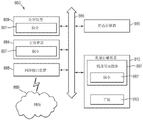
Fig. 1 illustrates a block diagram of an apparatus in the form of a computing system configured to perform interference management, in accordance with a number of embodiments of the present disclosure.
Fig. 2 illustrates an example of components associated with managing adjacent interference in accordance with several embodiments of the present disclosure.
FIG. 3 illustrates an example of an entry of a memory management unit address data structure configured for interference management, according to several embodiments of the present disclosure.
Fig. 4 illustrates an example of entries of a drift entry data structure configured for interference management, in accordance with several embodiments of the present disclosure.
FIG. 5 is an example of a curve illustrating a relationship between write disturb and time since last write to a particular location, in accordance with several embodiments of the present disclosure.
Fig. 6 is a flow diagram of an example of a method for interference management in accordance with several embodiments of the present disclosure.
Fig. 7 is a flow diagram of an example of a method that may include write disturb management and drift management, in accordance with several embodiments of the present disclosure.
Fig. 8 is a block diagram of an example apparatus in the form of a computer system in which embodiments of the present disclosure may operate in accordance with several embodiments of the present disclosure.
Detailed Description
Aspects of the present disclosure relate to write disturb management in a memory subsystem. An example of a memory subsystem is a storage system, such as a Solid State Drive (SSD). In some embodiments, the memory subsystem is a hybrid memory/storage subsystem. In general, a host system may utilize a memory subsystem that includes one or more memory components. The host system may provide data to be stored in the memory subsystem and may request data to be retrieved from the memory subsystem.
Various embodiments provide technical improvements, such as improved handling of neighbor interference compared to existing approaches. For example, various embodiments provide a more accurate determination of thermal write disturb for a resistance variable memory cell (e.g., victim) that is adjacent to the resistance variable memory cell being written (e.g., aggressor) by basing the determination on the time between writes to the aggressor (e.g., the frequency of writes to the aggressor). This allows a more accurate determination of when to refresh the victim to correct thermal disturbances than existing methods.
For example, the write disturb count corresponding to the victim may be incremented by an increment based on the time count between in-situ writes to the aggressor. In response to the disturbance count reaching a threshold count, a refresh operation may be performed on the victim.
The respective states (e.g., stored data values) of the resistance variable memory cells can depend on the respective programmed resistances of the memory cells corresponding to the respective threshold voltages (Vt) of the cells. In some examples, the resistance variable memory cell may be rewritten by overwriting the resistance variable memory cell without first erasing the resistance variable memory cell. This may be referred to as in-situ writing. The state of a resistance variable memory cell can be determined (e.g., read), for example, by sensing a current through the cell in response to an applied sensing (e.g., read) voltage.
When an aggressor resistance variable cell is written in situ, the temperature of the aggressor cell can rise, particularly when the aggressor cell is repeatedly written over a short period of time (e.g., within about 10 to 20 milliseconds). As the temperature of the aggressor cell increases, more heat is transferred to the victim cell, resulting in an increase in the temperature of the victim cell. The amount by which the victim cell temperature rises may depend on the time between writes to the aggressor cell. For example, the shorter the time between writes to the aggressor cell, the greater the temperature rise of the victim cell.
The elevated temperature may cause the programmed resistance of the victim cell to change, making it difficult to read the victim with the predetermined read voltage. This may be referred to as a hot write disturb. For example, the amount of thermal write disturb to a victim cell may depend on the time between writes to aggressor cells. The victim cell may be refreshed by rewriting it back to its properly programmed resistance state.
The interference counter may be used to record interference to the victim unit. If the disturb count is greater than the threshold, the victim cell may be refreshed. In existing approaches, the counter may be incremented by increments that do not depend on the time between writes (e.g., consecutive writes) to the aggressor cell, and thus may not accurately account for thermal disturbances. For example, in existing approaches, the counter may be incremented at the same rate for all victim cells. However, in situations where an aggressor experiences relatively frequent writes over a relatively short time interval, this may result in victim cell refresh frequencies that are too low. For example, writing an aggressor frequently in a short time interval may cause more interference to the victim than the same number of writes to the aggressor over a longer period. In such examples, a victim who has experienced a large disturb is more likely to experience a read error, although the same number of disturb events due to writes to an aggressor have been experienced.
Incrementing the disturb count by a disturb count increment based on the time between writes may be used to account for the amount of thermal disturb to the victim. For example, the disturb count may be accelerated for a short time between writes (e.g., greater thermal disturb) as compared to the disturb count for a longer time between writes (e.g., less thermal disturb). This may provide the ability to refresh the victim at a more appropriate time (e.g., before the time the victim is disturbed to the point where it stores an erroneous data value).
Fig. 1 illustrates a block diagram of an apparatus in the form of a computing system 100 configured to perform interference management, in accordance with a number of embodiments of the present disclosure. As used herein, "device" may refer to, but is not limited to, various structures or combinations of structures. For example, the memory system 104, the controller 108, and the memory components 110-1 through 110-N may be considered "devices" individually.
The memory system 104 may be, for example, a storage system such as a Solid State Drive (SSD), an embedded multimedia controller (eMMC) device, a Universal Flash Storage (UFS) device, and the like, and may include an interface 106, a controller 108, and a number of memory components 110-1 through 110-N, which may be collectively referred to as memory 110. The memory component 110 may provide storage capacity for the memory system 104; however, one or more of the memory components 110 may be used as main memory for the system 100. In several embodiments, the memory system 104 is a memory subsystem, a hybrid memory/storage system, or the like.
As illustrated in fig. 1, the memory system 104 may be coupled to the host 102 via an interface 106. The host 102 may be a host system, such as a personal laptop computer, a desktop computer, a digital camera, a mobile device (e.g., a cellular phone), a web server, an internet of things (IoT) enabled device, or a memory card reader, among various other types of hosts. The host 102 may include a number of memory access devices (e.g., a number of processors) capable of accessing the memory components 110 (e.g., via the controller 108).
In the example illustrated in fig. 1, the controller 108 is coupled to the memory component 110 via a plurality of channels and may be used to transfer data between the memory system 104 and the host 102 (e.g., via the interface 106). The interface 106 may be in the form of a standardized interface. For example, when memory system 104 is used for data storage in computing system 100, interface 106 may be a Serial Advanced Technology Attachment (SATA), peripheral component interconnect express (PCIe), or Universal Serial Bus (USB), among other connectors and interfaces. In general, however, the interface 106 may provide an interface for passing control, address, data, and other signals between the memory system 104 and the host 102 with compatible receptors for the interface 106.
The controller 108 may communicate with the memory component 110 to control data read, write, and erase operations, among other operations. Although not specifically illustrated, in some embodiments, the controller 108 may include a discrete memory channel controller for each channel coupling the controller 108 to the memory components 110. The controller 108 may include a number of components, e.g., in the form of hardware (e.g., one or more integrated circuits) and/or software (e.g., instructions, which may be in the form of firmware), for controlling access to a number of memory components 110 and/or for facilitating data transfers between the host 102 and the memory components 110. In general, the controller 108 may receive commands (e.g., operations) from the host 102 and may convert the commands into instructions or appropriate commands to achieve the desired access to the memory components 110.
As further described herein, the controller 108 may be responsible for memory management operations such as interference management (e.g., mitigation) operations, drift management operations, error detection and/or correction operations, and address translation operations, among other operations, as well as various other operations associated with the memory component 110. The controller may perform memory management in association with performing background operations and/or foreground operations. Foreground operations may include operations initiated by a host (e.g., host 102), such as read and/or write access commands. Background operations may include operations initiated by a controller (e.g., 108) and/or whose execution may be transparent to a host (e.g., host 102), such as neighbor interference mitigation operations performed in accordance with embodiments of the present disclosure.
As used herein, a storage element refers to a programmable portion of a memory cell. For example, the memory component 110 may be a 3D cross-point device, the cells of which may include a "stacked" structure in which storage elements and switching elements are coupled in series, and which may be referred to herein as 3D Phase Change Material and Switch (PCMS) devices. The 3D-PCMS cell may include, for example, a two-terminal chalcogenide memory element coupled in series with a two-terminal chalcogenide switching element, such as an Ovonic Threshold Switch (OTS). In several embodiments, the memory cells can be self-selecting memory (SSM) cells, where a single material can serve as both a storage element and a memory element. The SSM unit may comprise a chalcogenide alloy; however, the embodiments are not limited thereto.
As a non-limiting example, the memory cells of memory component 110 may include a phase change material (e.g., a phase change chalcogenide alloy), such as an indium (In) -antimony (Sb) -tellurium (Te) (IST) material (e.g., In)2Sb2Te5、In1Sb2Te4、In1Sb4Te7Etc.) or germanium (Ge) -antimony (Sb) -tellurium (Te) (GST) materials (e.g., Ge2Sb2Te5、Ge1Sb2Te4、Ge1Sb4Te7Etc.). Hyphenated chemical composition notation, as used herein, indicates the elements included in a particular mixture or compound, and is intended to represent all stoichiometric ratios related to the indicated elements. Other memory cell materials may include GeTe, In-Se, Sb2Te3、GaSb、InSb、As-Te、Al-Te、Ge-Sb-Te、Te-Ge-As、In-Sb-Te、Te-Sn-Se、Ge-Se-Ga、Bi-Se-Sb、Ga-Se-Te、Sn-Sb-Te、In-Sb-Ge、Te-Ge-Sb-S、Te-Ge-Sn-O、Te-Ge-Sn-Au、Pd-Te-Ge-Sn、In-Se-Ti-Co、Ge-Sb-Te-Pd、Ge-Sb-Te-Co、Sb-Te-Bi-Se、Ag-In-Sb-Te、Ge-Sb-Se-Te、Ge-Sn-Sb-Te、Ge-Te-Sn-Ni, Ge-Te-Sn-Pd, and Ge-Te-Sn-Pt, as well as various other materials.
As shown in fig. 1, according to embodiments described herein, the controller 108 includes a processing device 109 and a memory management component 111 configured to perform various memory management operations. In this example, the memory management component 111 includes a neighboring interference management component 113, a drift management component 117, and an error detection/correction component 115 (e.g., an Error Correction Code (ECC) engine). The memory management component 111 also includes a number of data structures 114. As used herein, "data structure" refers to a format for organizing and/or storing data, examples of which include tables, arrays, files, list records, queues, trees, and the like. As described further below, the data structures 114 may include logical-to-physical (L2P) address mapping data structures (e.g., tables) for mapping logical Managed Unit Address (MUA) addresses to Physical Managed Units (PMUs) stored in the memory 110 and the drift table. In some examples, the data structure 114 may include a lookup table for determining a disturb increment for incrementing a disturb count corresponding to a memory cell adjacent to a memory cell being in-situ written as a function of time between in-situ writes to the memory cell. It should be noted that the terms "table" and "list" used to describe a particular data structure 114 are intended only as non-limiting examples.
The various components 113, 114, 115, and 117 of the memory management component 111 may be discrete components, such as Application Specific Integrated Circuits (ASICs), or the components may reflect functionality provided by circuitry within the controller 108 that does not necessarily have a discrete physical form separate from other portions of the controller 108. Although illustrated in FIG. 1 as a component within memory management component 111, each of components 113, 114, 115, and 117, or portions thereof, may be external to memory management component 111 and/or external to controller 108. For example, the error detection/correction component 115 may include a number of error correction coding circuits located on the controller 108 and a number of error correction coding circuits located external to the controller 108.
Fig. 2 illustrates an example of components associated with managing neighbor disturbs (e.g., thermal write disturbs) in accordance with several embodiments of the present disclosure. In FIG. 2, the Management Unit Address (MUA) table 220 represents a logical address to physical address (L2P) data structure associated with mapping physical memory 210. The table 220 may be one of the data structures 114 maintained by a controller (e.g., the controller 108), and the memory 210 may represent a memory, such as the memory 110 shown in fig. 1.
In operation, a host (e.g., host 102) may use logical addressing (e.g., logical block addressing) to identify logical areas (e.g., sectors) of data. As an example, a logical address may correspond to 256 bytes, 512 bytes, 1,024 bytes, and so on. Logical addresses (e.g., Logical Block Addresses (LBAs)) may be organized by a controller (e.g., controller 108) into Managed Units (MUs), which may refer to units (e.g., sizes) of memory managed by the controller (e.g., via an L2P table). As an example, logical mua (lmua) may correspond to multiple host LBAs, such that MUs may correspond to 2KB, 4KB, 8KB, and so on. The size of the MU may also be related to write and/or read sizes associated with the mapped memory (e.g., memory 210). For example, MUs may correspond to a number of memory cells, such as a group of resistance variable memory cells (e.g., physical MUs (pmus)). For example, the MU size may be a multiple of a physical page size of the memory, a multiple of a codeword size associated with the memory, and so on.
As shown in fig. 2, MUA entries 221-1 through 221-M of table 220 may be indexed by LMUA, with each entry including a Physical Managed Unit Address (PMUA) indicating (e.g., pointing to) a location of a corresponding PMU in memory 210. For example, as shown in FIG. 2, PMUA-1 in MUA entry 221-1 points to PMU 217-1, and PMUA-2 in MUA entry 221-2 points to PMU 217-2. In several embodiments, the data stored in the group of cells corresponding to PMU 217 may include user data and/or parity data, as well as various metadata, which may include LMUAs that are currently mapped to PMUAs corresponding to PMU 217.
Fig. 2 also illustrates an example of a Drift Entry Table (DET)225, which may be the data structure 114. The DET 225 may include a drift entry 226, which may be referenced (e.g., pointed to) by a drift entry index in a MUA entry (e.g., MUA entry 221-1), while a number of memory cells in a PMU (e.g., PMU 217-1) corresponding to MUA entry 221-1 are in drift. In some examples, the drift tail may be the next drift entry in the DET 225 to exit from drift, and the drift head may be the next drift entry in the DET 225 to write.
For example, when writing (e.g., programming) a resistance variable cell, its resistance state may change (e.g., drift) over a certain period of time (e.g., a drift period) until a stable resistance state is reached. For example, the data read during the drift period may be unreliable.
FIG. 2 further illustrates an example of a Drift Data Buffer (DDB)230, such as a DRAM buffer. Location 232 in DDB230 having the address specified in drift entry 226 may temporarily store data during a drift period in which several cells in PMU 217-1 that simultaneously store the same data are in drift. For example, in response to a read command specifying an LMUA corresponding to (e.g., its index of) MUA entry 221-1, memory management component 108 may determine from the drift indicator in read MUA entry 221-1 whether PMU 217-1 is in drift.
In response to determining that PMU 217-1 is in drift, memory management component 111 may activate drift management component 117 to perform drift management operations. For example, drift management component 117 may read drift entry 226 in response to reading the drift entry index in MUA entry 221-1 that references drift entry 226. The drift management component 117 can then read data from the location 232 in response to reading the address of the location 232 from the drift entry 226.
Data may be read from DDB230 instead of PMU 217-1 whenever PMU 217-1 is determined to be in drift. After a certain period of time corresponding to a drift period, the memory management component 111 may set a drift indicator to indicate that PMU 217-1 is not in drift. The memory management component 111 may then read data from the PMU 217-1 in response to determining from the read drift indicator that the PMU 217-1 is not drifting.
Fig. 3 illustrates an example of MUA entry 321 that may be MUA entry 221 and configured for interference management, according to several embodiments of the present disclosure. For example, MUA entry 321 includes a field 340 that can store the PMUA of addressable PMU 217. The MUA entry 321 includes an interference counter field 342, a drift indicator field 344 that can store a drift indicator, such as a flag, and a drift entry index field 346 that can store a drift entry (e.g., drift entry 226) that can reference (e.g., point to) the drift entry in the DET 225.
Fig. 4 illustrates an example of a drift entry 426 that may be a drift entry 226 and configured for interference management, according to several embodiments of the present disclosure. Drift entry 426 may include an LMUA field 450 that may store an LMUA that may refer back to a MUA entry, such as MUA entry 221-1, whose drift entry index references drift entry 426. For example, the drift entry index in field 346 may reference drift entry 426, and the LMUA in field 450 may be the LMUA of MUA entry 321. Drift entry 426 includes a timestamp field 452 that may store a timestamp that may be the time of the last write of the number of memory units in PMU 217 that correspond to LMUA in field 450. For example, LMUA may correspond to MUA entry 221-1 corresponding to PMU 217-1, and the timestamp may be the time the memory unit in PMU 217-1 was last written. Drift entry 426 may include DDB address field 454, which may store the DDB address of a location in DDB 230.
In the example where the LMUA in field 450 corresponds to MUA entry 221-1, if the timestamp is greater than the threshold drift time, meaning that the memory cells in PMU 217-1 are no longer in drift, drift management component 117 may exit the drift entry (e.g., drift entry 426) referenced by MUA entry 221-1. For example, if the drift indicator in MUA entry 221-1 points to a drift tail (e.g., drift entry 426 is a drift tail), then drift entry 426 is valid and retired, and the drift tail is incremented to the next drift entry, thereby freeing drift entry 426 and the location in DDB230 having the DDB address in field 454 for further writes. For example, drift management component 117 may set a drift indicator in MUA entry 221-1 in response to exiting drift entry 426 to indicate that PMU 217-1 is not in drift. If the drift indicator in MUA entry 221-1 does not point to a drift tail (e.g., drift entry 426 is not a drift tail), then drift entry 426 is invalid (e.g., expired) and the drift indicator in MUA entry 221-1 remains unchanged.
In some examples, a number of memory cells in PMU 217-2 may be adjacent to a number of memory cells in PMU 217-1. For example, a memory cell in PMU 217-2 may be write disturbed due to an in-place write to memory cell PMU 217-1. The amount of disturbance experienced by the memory cells in PMU 217-2 may depend on the frequency of writes to the memory cells in PMU 217-1. For example, the higher the frequency of writing, the greater the interference. For example, the smaller the time interval between writes, the higher the frequency and the greater the interference. In some examples, the count increment by which the interference count corresponding to a memory cell in PMU 217-2 may be incremented may be based on a time interval (e.g., frequency) between successive writes to the memory cell of PMU 217-1. In an example where MUA 321 is MUA 221-2, the interference count of the interference counter in field 342 may be incremented by a count increment (e.g., an interference count increment) based on a time interval between writes to memory cells of PMU 217-1.
FIG. 5 is an example of a curve illustrating a relationship between write disturb and time since last write to a particular location, in accordance with several embodiments of the present disclosure. For example, curve 560 illustrates a relationship between an amount (e.g., an interference count increment) used to increment an interference count corresponding to a memory cell (e.g., a number of memory cells in a PMU (e.g., PMU 221-2)) and a consecutive write time interval (e.g., a time between consecutive in-place writes to an adjacent memory cell (e.g., in an adjacent PMU (e.g., PMU 221-1)). In some examples, curve 560 may correspond to an exponential decay function. However, the present disclosure is not so limited, and the time between disturb count increments and writes may be a linear relationship, as well as other functional relationships. In some examples, the disturb count increments may be tabulated in terms of (e.g., indexed by) consecutive write time intervals in a lookup table, which may be the data structure 114. As shown in fig. 5, the disturb count increment decreases with increasing successive write time intervals (e.g., decreasing write frequency). In some examples, the consecutive write time interval may be the time difference between the time the memory cell was last written (e.g., the timestamp in field 452) and the current time the memory cell is currently written.
The consecutive write time intervals may be divided into a range of consecutive write time intervals, which may be referred to as bins (bins). For example, in FIG. 5, the range of consecutive write time intervals 562-1 through 562-4 may be referred to as bins 1 through 4, respectively. The respective disturb count increment corresponding to a consecutive write time interval at the beginning of the respective range (e.g., the lowest consecutive write time interval) can be the respective disturb count increment for the respective range. For example, discrete interference count increments corresponding to data symbols 564-1 through 564-4, respectively, may be for ranges 562-1 through 562-4, respectively. In some examples, the increment of the disturb count, such as at the beginning of the range (e.g., at the lowest consecutive write time interval of the range), may be tabulated against a range of lookup tables that may be the data structure 114. In an example, if the determined time between writes is within a particular range, such as range 562-3, the disturb count increment is a disturb count increment for that range, such as a disturb count corresponding to data point 564-3.
The memory array that may be in memory 110 may be a 3D cross-point memory array, which may include several stacks of memory cell planes, such as the resistance variable cells previously described. In each plane, groups of memory cells, which may be referred to as rows of memory cells, may be commonly coupled to access lines, which may be referred to as word lines. Each plane may also include a group of memory cells, which may be referred to as columns of memory cells, which may be commonly coupled to access lines, which may be referred to as data lines (e.g., bit lines) that may be coupled to sense amplifiers. For example, a column may intersect (e.g., cross) a row.
In some examples, neighboring cells that neighbor an aggressor cell may be direct neighbors that are directly adjacent to an aggressor cell without any intervening cells. For example, aggressor cells can have direct neighbors within the same plane or in different planes.
The amount of interference to neighboring cells depends on their spatial relationship to the aggressor cell. For example, interference to neighboring cells may depend on the direction from an aggressor cell. For example, the interference to neighboring cells along a bit line may be greater than the interference to neighboring cells along a word line. Thus, for the same time between writes, the disturb count increment for adjacent cells along the bit line may be greater than the disturb count increment for adjacent cells along the word line. Thus, for different spatial relationships, there may be different functional relationships between the disturb count increment and the time between writes. For example, for each spatial relationship, there may be a different look-up table of disturb count increments and time between writes. The interference management component 113 can determine the interference count increment by selecting a functional relationship (e.g., a look-up table) for a particular spatial relationship, and then determining the interference count increment from the time between writes by the selected functional relationship.
Fig. 6 is a flow diagram of an example of a method 670 for interference management according to several embodiments of the present disclosure. For example, method 670 may be performed by interference management component 113.
At block 671, a time between writes to the memory cells is determined. For example, the time between writes may be the difference between the current time that the memory cell is currently being written to and the time that the memory cell was last written to. For example, the time that the memory cell was last written to may be a timestamp in a drift entry referenced by a MUA entry corresponding to a PMU that includes the memory cell. The time stamp can be read to determine the time the memory cell was last written. After the timestamp is read, it may be updated to the current time.
In some examples, when a write occurs to a memory cell that is already in drift, the current DET entry in the DET 225 referenced by the MUA entry corresponding to the PMU containing the memory cell may be read to determine the time the memory cell was last written. For example, by writing an update timestamp in a new DET entry in the DET 225, the timestamp can be updated to the current time after the timestamp is read. The current DET entry may then be invalidated, and the MUA entry corresponding to the PMU containing the memory unit may be updated to reference the new DET entry.
At block 672, the disturb count corresponding to the neighboring memory cell may be incremented by a particular amount based on the time between writes. The disturb count increment may be determined from a relationship between the particular amount and the time between writes, such as from the relationship in FIG. 5. For example, the particular amount may be an interference count increment, such as an interference count increment corresponding to data point 564-3, which corresponds to a range of consecutive write time intervals including the determined time between writes, such as range 562-3. At block 673, a refresh operation is performed on the neighboring cell in response to the disturb count reaching the threshold count.
Fig. 7 is a flow diagram of an example of a method 775 that can include write disturb management and drift management, according to several embodiments of the present disclosure. For example, the method 775 may be performed at least in part by the interference management component 113 and the drift management component 117.
At block 776, the MUA entry in read table 220 corresponding to the LMUA in the received write command, e.g., MUA entry 221-1. At block 777, a number of memory cells in a PMU (e.g., PMU 217-1) corresponding to a PMUA (e.g., PMUA-1) in the MUA entry are determined to be in drift according to a drift indicator in the MUA entry. At block 778, the time that the PMU was last written is determined from a timestamp in a drift entry (e.g., drift entry 226) in table 225 referenced by a drift entry index in the MUA entry. For example, the timestamps may be read in response to determining that the memory cells in the PMU are in drift.
At block 779, a time difference between the current time associated with the write command and the time that the PMU was last written is determined. For example, the time difference may be a continuous write time interval for a number of cells in the PMU, such as the time between successive writes to a number of cells in the PMU, and may represent the frequency of writes to the PMU.
At block 780, the interference count in the MUA entry in table 220 corresponding to the PMU (e.g., PMU 217-2) containing several neighboring memory cells is incremented by an interference count increment based on a time difference, e.g., by interference management component 113 as part of interference management. For example, a neighboring memory cell in PMU 217-2 may be adjacent to a memory cell in PMU 217-1. In some examples, after incrementing the interference count, a drift entry index in MUA entry 221-1 may be set (e.g., cleared), e.g., by drift manager 117, to indicate that the drift entry is invalid. Additionally, a drift indicator may be set to indicate that a memory cell in PMU 217-1 is not in drift.
As previously discussed, the disturb count increment can be determined by a functional relationship between the disturb count increment and the successive write time interval. For example, the disturb count increment can correspond to a range of consecutive write time intervals including consecutive write time intervals. In some examples, the functional relationship may be selected based on a spatial relationship between memory cells in PMU 217-1 and PMU 217-2. At block 781, a refresh operation is performed on a PMU including the number of neighboring memory cells in response to the disturb count reaching the threshold count. In some examples, the disturb count corresponding to the PMU including the number of neighboring memory cells may be reset in response to performing the refresh operation.
In some examples, the data in the write command is written simultaneously to PMUs corresponding to PMUA in MUA entries corresponding to LMUA and entries in DDB 230. For example, data may be written after the drift entry index in MUA entry 221-1 is set (e.g., cleared) to indicate that the drift entry is invalid and after the drift indicator in MUA entry 221-1 is set to indicate no drift.
The drift indicator MUA entry 221-1 may be set to indicate that a cell in PMU 217-1 is in drift, and the drift entry index in MUA entry 221-1 may be set to refer to the next drift entry (e.g., after drift entry 226). A timestamp field in the drift entry may be set to the current time. The DDB address in the drift entry may then be set to a location in DDB230, and the data in the write command may be written to PMU 217-1 and the location in DDB230 having the DDB address at the same time.
Fig. 8 is a block diagram of an example apparatus in the form of a computer system 883, in which embodiments of the disclosure may operate. For example, the computer system 883 may include or utilize a memory system, such as the memory system 104 of fig. 1 (e.g., SSD, eMMC device, UFS). The system 883 may also be a system such as the computing system 100 shown in fig. 1. The system 883 may be a Personal Computer (PC), a tablet PC, a set-top box (STB), a Personal Digital Assistant (PDA), a cellular telephone, a web appliance, a server, a network router, switch or bridge, or any machine capable of executing a set of instructions (sequential or otherwise) that specify actions to be taken by that machine. Further, while a single machine is illustrated, the term "machine" shall also be taken to include any collection of machines that individually or jointly execute a set (or multiple sets) of instructions to perform any one or more of the methodologies discussed herein.
An example computer system 883 includes a processing device 809, a main memory 884 (e.g., Read Only Memory (ROM), flash memory, Dynamic Random Access Memory (DRAM), such as synchronous DRAM (sdram) or Rambus DRAM (RDRAM), etc.), a static memory 885 (e.g., flash memory, Static Random Access Memory (SRAM), etc.), and a data storage device 810, which communicate with each other via a bus 886.
The data storage 810 may include an interference management component 813, which may be similar to (e.g., the same as) the interference management component 113. The data storage device 810 may include a machine-readable storage medium 897 (also referred to as a computer-readable medium) on which is stored one or more sets of instructions 887 (e.g., software) embodying one or more of the various methods or functions described herein. The instructions 887 may also reside, completely or at least partially, within the main memory 884 and/or within the processing device 808 during execution thereof by the computer system 883, the main memory 884 and the processing device 808 also constituting machine-readable storage media. The machine-readable storage medium 897, data storage device 810, and/or main memory 884 may correspond to the memory system 104 of fig. 1.
The present disclosure also relates to apparatus for performing the operations herein. This apparatus may be specially constructed for the intended purposes, or it may comprise a general purpose computer selectively activated or reconfigured by a computer program stored in the computer. Such a computer program may be stored in a computer readable storage medium, such as, but is not limited to, any type of disk including floppy disks, optical disks, CD-ROMs, and magnetic-optical disks, read-only memories (ROMs), Random Access Memories (RAMs), EPROMs, EEPROMs, magnetic or optical cards, or any type of media suitable for storing electronic instructions, and each coupled to a computer system bus.
The algorithms and displays presented herein are not inherently related to any particular computer or other apparatus. Various general-purpose systems may be used with programs in accordance with the teachings herein, or it may prove convenient to construct a more specialized apparatus to perform the method. The structure for a variety of these systems will appear as set forth in the description below. In addition, the present disclosure is not described with reference to any particular programming language. It will be appreciated that a variety of programming languages may be used to implement the teachings of the disclosure as described herein.
The present disclosure may be provided as a computer program product or software which may include a machine-readable medium having stored thereon instructions which may be used to program a computer system (or other electronic devices) to perform a process according to the present disclosure.
As used herein, "a" or "an" may refer to one or more of something, and "something" may refer to one or more of such things. For example, a number of memory cells may refer to one or more memory cells. "plurality" means two or more. As used herein, performing multiple actions simultaneously refers to actions that at least partially overlap within a particular time period. As used herein, the term "coupled" may include not electrically coupled, directly coupled, and/or directly connected (e.g., by direct physical contact) to the intervening elements, or indirectly coupled and/or connected to the intervening elements. The term "coupled" may further include two or more elements that cooperate or interact with each other (e.g., in a causal relationship).
Various methods of the present disclosure, such as the methods described in fig. 6 and 7, may be performed by processing logic in the form of hardware (e.g., processing devices, such as processors, control circuitry, dedicated logic, programmable logic, integrated circuits, etc.) and/or software (e.g., instructions, which may comprise firmware, and which may be executed by a processing device) and/or combinations thereof.
Although specific embodiments have been illustrated and described herein, it will be appreciated by those of ordinary skill in the art that an arrangement calculated to achieve the same results may be substituted for the specific embodiments shown. This disclosure is intended to cover adaptations or variations of several embodiments of the present disclosure. It is to be understood that the above description has been made in an illustrative fashion, and not a restrictive one. Combinations of the above embodiments, and other embodiments not specifically described herein, will be apparent to those of ordinary skill in the art upon reviewing the above description. The scope of the several embodiments of the present disclosure includes other applications in which the above structures and methods are used. The scope of several embodiments of the disclosure should, therefore, be determined with reference to the appended claims, along with the full scope of equivalents to which such claims are entitled.
In the foregoing detailed description, certain features are grouped together in a single embodiment for the purpose of streamlining the disclosure. This method of disclosure is not to be interpreted as reflecting an intention that the disclosed embodiments of the disclosure have to use more features than are expressly recited in each claim. Rather, as the following claims reflect, inventive subject matter lies in less than all features of a single disclosed embodiment. Thus, the following claims are hereby incorporated into the detailed description, with each claim standing on its own as a separate embodiment.
Claims (20)
1. A method for interference management, comprising:
determining a time between in-situ writes to a memory cell;
incrementing a disturb count corresponding to a neighboring memory cell by a particular amount based on the time between the in-place writes to the memory cell; and
in response to the disturb count reaching a threshold count, performing a refresh operation on the neighboring cell.
2. The method of claim 1, further comprising incrementing the disturb count corresponding to the neighboring cell by a different particular amount that depends on the time between writes to the memory cell.
3. The method of claim 2, further comprising:
incrementing the disturb count corresponding to the memory cell by a first particular amount in response to the time between the in-place writes to the memory cell being a first value; and
incrementing the disturb count corresponding to the memory cell by a second particular amount in response to the time between the in-place writes to the memory cell being a second value;
wherein the first particular quantity is greater than the second particular quantity in response to the first value being less than the second value, and wherein the first particular quantity is less than the second particular quantity in response to the first value being greater than the second value.
4. The method of claim 2, wherein performing the refresh operation on the neighboring cell comprises reading a data value from the neighboring cell and rewriting the data value read from the neighboring cell back to a neighboring memory cell.
5. The method of claim 2, further comprising resetting the disturb count corresponding to the neighboring cell in response to performing the refresh operation.
6. The method of claim 1, further comprising determining the particular amount by accessing a data structure indexed by successive write time intervals, the successive write time intervals corresponding to different respective disturb count increments.
7. The method of claim 6, wherein the respective disturb count increments decrease as the corresponding consecutive write time intervals increase, and wherein the method includes selecting the particular disturb count increment based on which of the consecutive write time intervals the time between the in-place writes to the memory cell falls.
8. The method of claim 1, wherein incrementing the disturb value corresponding to the neighboring memory cell by the particular amount based on the time between the in-place writes to the memory cell further comprises determining the particular amount based on a spatial relationship between the memory cell and the neighboring memory cell.
9. The method of claim 1, wherein the method includes determining whether the memory cell is currently in drift.
10. The method of claim 9, further comprising determining whether the memory cell is currently in drift by accessing a data structure that includes an entry corresponding to a physical address of a managed cell that is currently in drift.
11. The method of claim 1, wherein incrementing the disturb count corresponding to the neighboring memory cell by the particular amount comprises incrementing a disturb count in a disturb count field in an entry of a data structure that includes a physical address of a physically managed unit corresponding to the neighboring memory cell.
12. A system for performing interference management, comprising:
a memory component comprising a number of physical managed elements;
a processing device coupled to the memory component and configured to:
in response to receiving a write command to a particular physical managed unit, determining an amount of time since the particular physical managed unit was last written to;
incrementing an interference count corresponding to a neighboring physical managed element by a particular amount based on the determined amount of time; and
in response to the interference count reaching a threshold count, performing a refresh operation on the neighboring physical managed unit.
13. The system of claim 12, wherein the processing device is configured to:
determining the amount of time since the particular physical managed element was last written based on a difference between a current time and a time the particular physical managed element was last written; and
determining whether the particular physical managed element is in drift based on the difference between the current time and the time the particular physical managed element was last written.
14. The system of claim 12, wherein the system comprises a memory management component configured to maintain a data structure whose entries correspond to respective physical managed units, wherein each entry comprises:
a physical address corresponding to a respective physical managed element; and
a drift indicator corresponding to the respective physical managed element; and is
Wherein the processing device is configured to determine whether the particular physical managed element is currently in drift based on the drift indicator.
15. The system of claim 14, wherein each entry of the data structure comprises a respective interference count field, and wherein the processing device is configured to increment the interference count corresponding to the neighboring physical managed unit by the particular amount.
16. The system of claim 14, wherein:
the data structure is a first data structure;
the memory management component configured to maintain a second data structure whose entries are referenced by indices in respective entries in the first data structure;
the processing device is configured to determine, from timestamps in entries in the second data structure that are referenced by the index in the respective entry in the first data structure corresponding to the particular physical managed unit, the time that the particular physical managed unit was last written to; and
the entry in the second data structure is referenced by the index in the respective entry in the first data structure only when the corresponding drift indicator in the respective entry in the first data structure indicates that the particular physical managed element is in drift.
17. The system of claim 16, wherein the processing device is configured to write data to the particular physical managed unit and to a location in a buffer specified in the entry in the second data structure.
18. An apparatus for performing interference management, comprising:
a memory component;
a controller coupled to the memory component and configured to:
determining a time between successive in-place writes to memory cells in the memory component;
incrementing a disturb count corresponding to a neighboring memory cell in the memory component by a particular amount based on the time between the successive in-place writes to the memory cell; and
in response to the disturb count reaching a threshold count, performing a refresh operation on the neighboring cell.
19. The apparatus of claim 18, wherein:
the respective ranges of successive write time intervals correspond to respective count increments; and
the controller is configured to determine the particular quantity from the respective count increments corresponding to a range of consecutive write time intervals that includes a determined time corresponding to between consecutive writes.
20. The apparatus of claim 18, wherein the particular amount is further based on a spatial relationship between the memory cell and the neighboring memory cell.
Applications Claiming Priority (3)
| Application Number | Priority Date | Filing Date | Title |
|---|---|---|---|
| US16/110,758 US10586592B1 (en) | 2018-08-23 | 2018-08-23 | Disturb management based on write times |
| US16/110,758 | 2018-08-23 | ||
| PCT/US2019/047460 WO2020041442A1 (en) | 2018-08-23 | 2019-08-21 | Disturb management based on write times |
Publications (2)
| Publication Number | Publication Date |
|---|---|
| CN112639979A CN112639979A (en) | 2021-04-09 |
| CN112639979B true CN112639979B (en) | 2022-04-19 |
Family
ID=69586458
Family Applications (1)
| Application Number | Title | Priority Date | Filing Date |
|---|---|---|---|
| CN201980055628.2A Active CN112639979B (en) | 2018-08-23 | 2019-08-21 | Write time based interference management |
Country Status (5)
| Country | Link |
|---|---|
| US (3) | US10586592B1 (en) |
| EP (1) | EP3841582A4 (en) |
| KR (1) | KR102373852B1 (en) |
| CN (1) | CN112639979B (en) |
| WO (1) | WO2020041442A1 (en) |
Families Citing this family (8)
| Publication number | Priority date | Publication date | Assignee | Title |
|---|---|---|---|---|
| US9123414B2 (en) * | 2013-11-22 | 2015-09-01 | Micron Technology, Inc. | Memory systems and memory programming methods |
| US9336875B2 (en) | 2013-12-16 | 2016-05-10 | Micron Technology, Inc. | Memory systems and memory programming methods |
| US10672486B2 (en) * | 2018-08-21 | 2020-06-02 | Micron Technology, Inc. | Refreshing data stored at a memory component based on a memory component characteristic component |
| US11056166B2 (en) * | 2019-07-17 | 2021-07-06 | Micron Technology, Inc. | Performing a refresh operation based on a characteristic of a memory sub-system |
| US11113002B2 (en) * | 2019-10-25 | 2021-09-07 | Seagate Technology Llc | Command overlap checking in a data storage device |
| US11776611B2 (en) * | 2021-08-03 | 2023-10-03 | Micron Technology, Inc. | Managing write disturb for units of a memory device using weighted write disturb counts |
| US11656940B2 (en) * | 2021-08-13 | 2023-05-23 | Micron Technology, Inc. | Techniques for managing temporarily retired blocks of a memory system |
| US20240061614A1 (en) * | 2022-08-18 | 2024-02-22 | Micron Technology, Inc. | Error detection and correction in a controller |
Citations (2)
| Publication number | Priority date | Publication date | Assignee | Title |
|---|---|---|---|---|
| CN1941176A (en) * | 2005-09-27 | 2007-04-04 | 三洋电机株式会社 | Memory |
| JP2013004158A (en) * | 2011-06-21 | 2013-01-07 | Elpida Memory Inc | Semiconductor storage device and refresh control method thereof |
Family Cites Families (22)
| Publication number | Priority date | Publication date | Assignee | Title |
|---|---|---|---|---|
| FR2442488A1 (en) * | 1978-11-22 | 1980-06-20 | Cii Honeywell Bull | DEVICE FOR EXTRACTING AND REWRITING INFORMATION FOR A COOLING MEMORY |
| US6931480B2 (en) * | 2001-08-30 | 2005-08-16 | Micron Technology, Inc. | Method and apparatus for refreshing memory to preserve data integrity |
| US20090109755A1 (en) * | 2007-10-24 | 2009-04-30 | Mori Edan | Neighbor block refresh for non-volatile memory |
| WO2010076829A1 (en) * | 2008-12-30 | 2010-07-08 | Massimo Iaculo | Wear leveling for erasable memories |
| US8261136B2 (en) * | 2009-06-29 | 2012-09-04 | Sandisk Technologies Inc. | Method and device for selectively refreshing a region of a memory of a data storage device |
| US8484410B2 (en) * | 2010-04-12 | 2013-07-09 | Intel Corporation | Method to stagger self refreshes |
| TWI490869B (en) * | 2010-08-13 | 2015-07-01 | Mstar Semiconductor Inc | Method and associated controller for flash memory |
| US9021227B2 (en) * | 2011-06-22 | 2015-04-28 | Intel Corporation | Drift management in a phase change memory and switch (PCMS) memory device |
| US9257169B2 (en) * | 2012-05-14 | 2016-02-09 | Samsung Electronics Co., Ltd. | Memory device, memory system, and operating methods thereof |
| US9104646B2 (en) * | 2012-12-12 | 2015-08-11 | Rambus Inc. | Memory disturbance recovery mechanism |
| US9202547B2 (en) | 2013-03-15 | 2015-12-01 | Intel Corporation | Managing disturbance induced errors |
| US8861109B1 (en) * | 2013-08-09 | 2014-10-14 | Lsi Corporation | Data processing system with adjacent track interference metric |
| US20150169406A1 (en) * | 2013-12-16 | 2015-06-18 | Sandisk Technologies Inc. | Decoding techniques for a data storage device |
| DE112015000378T5 (en) | 2014-01-09 | 2016-09-22 | Sandisk Technologies Inc. | Selective copyback for a chip-backed non-volatile memory |
| US10078546B2 (en) * | 2014-10-24 | 2018-09-18 | Micron Technology, Inc. | Temperature related error management |
| WO2016083865A1 (en) | 2014-11-25 | 2016-06-02 | 三星电子株式会社 | Probability information-based method of detecting most frequently-accessed address of semiconductor memory |
| US10241909B2 (en) | 2015-02-27 | 2019-03-26 | Hitachi, Ltd. | Non-volatile memory device |
| US9349431B1 (en) * | 2015-03-17 | 2016-05-24 | Qualcomm Incorporated | Systems and methods to refresh storage elements |
| CN107039059B (en) | 2016-02-01 | 2022-05-10 | 三星电子株式会社 | Memory package, memory module including the same, and memory package operation method |
| US10481830B2 (en) | 2016-07-25 | 2019-11-19 | Sandisk Technologies Llc | Selectively throttling host reads for read disturbs in non-volatile memory system |
| US10032500B2 (en) | 2016-10-07 | 2018-07-24 | Tc Lab, Inc. | Memory disturb recovery scheme for cross-point memory arrays |
| KR20180060084A (en) * | 2016-11-28 | 2018-06-07 | 삼성전자주식회사 | Scrubbing controller of a semiconductor memory device, semiconductor memory device and method of operating a semiconductor memory device |
-
2018
- 2018-08-23 US US16/110,758 patent/US10586592B1/en active Active
-
2019
- 2019-08-21 KR KR1020217008273A patent/KR102373852B1/en active IP Right Grant
- 2019-08-21 EP EP19852290.6A patent/EP3841582A4/en not_active Withdrawn
- 2019-08-21 CN CN201980055628.2A patent/CN112639979B/en active Active
- 2019-08-21 WO PCT/US2019/047460 patent/WO2020041442A1/en unknown
-
2020
- 2020-03-09 US US16/812,559 patent/US11133061B2/en active Active
-
2021
- 2021-08-30 US US17/460,415 patent/US11657872B2/en active Active
Patent Citations (2)
| Publication number | Priority date | Publication date | Assignee | Title |
|---|---|---|---|---|
| CN1941176A (en) * | 2005-09-27 | 2007-04-04 | 三洋电机株式会社 | Memory |
| JP2013004158A (en) * | 2011-06-21 | 2013-01-07 | Elpida Memory Inc | Semiconductor storage device and refresh control method thereof |
Also Published As
| Publication number | Publication date |
|---|---|
| US20200211645A1 (en) | 2020-07-02 |
| KR20210034682A (en) | 2021-03-30 |
| US11133061B2 (en) | 2021-09-28 |
| EP3841582A1 (en) | 2021-06-30 |
| KR102373852B1 (en) | 2022-03-14 |
| US10586592B1 (en) | 2020-03-10 |
| US11657872B2 (en) | 2023-05-23 |
| US20200066341A1 (en) | 2020-02-27 |
| US20210391007A1 (en) | 2021-12-16 |
| EP3841582A4 (en) | 2022-05-11 |
| WO2020041442A1 (en) | 2020-02-27 |
| CN112639979A (en) | 2021-04-09 |
Similar Documents
| Publication | Publication Date | Title |
|---|---|---|
| CN112639979B (en) | Write time based interference management | |
| US11556465B2 (en) | Memory management | |
| KR102569783B1 (en) | Out-of-order zone namespaces | |
| KR20210001898A (en) | Zone formation for zoned namespaces | |
| KR102261817B1 (en) | Resistive Memory Device and Resistive Memory System including a plurality of layers and Operating Method thereof | |
| US10303617B2 (en) | Storage device supporting byte accessible interface and block accessible interface and electronic system including the same | |
| KR20210057193A (en) | Hybrid wear leveling operation based on subtotal write counter | |
| WO2020263322A1 (en) | Hold of write commands in zoned namespaces | |
| KR20210028729A (en) | Logical vs. physical table fragments | |
| KR102268000B1 (en) | Memory management utilizing buffer reset commands | |
| CN114730290A (en) | Moving change log tables to align with partitions | |
| US11960753B2 (en) | Solution for super device imbalance in ZNS SSD | |
| US11966618B2 (en) | Purposeful super device imbalance for ZNS SSD efficiency | |
| KR101146082B1 (en) | Non-volatile memory storage and method for improving performance of non-volatile memory storage | |
| CN114730250A (en) | Weighting read commands according to partitions in a storage device | |
| US11537293B2 (en) | Wear leveling methods for zoned namespace solid state drive | |
| WO2023101719A1 (en) | Full die recovery in zns ssd | |
| KR102341698B1 (en) | Dedicated instructions for memory operations | |
| CN114830077A (en) | Data storage method and storage device | |
| US20240004566A1 (en) | Memory system for managing namespace using write pointer and write count, memory controller, and method for operating memory system | |
| TW202127262A (en) | Self-adaptive wear leveling method and algorithm |
Legal Events
| Date | Code | Title | Description |
|---|---|---|---|
| PB01 | Publication | ||
| PB01 | Publication | ||
| SE01 | Entry into force of request for substantive examination | ||
| SE01 | Entry into force of request for substantive examination | ||
| GR01 | Patent grant | ||
| GR01 | Patent grant |