CN112627508A - Novel building engineering formwork supports device - Google Patents
Novel building engineering formwork supports device Download PDFInfo
- Publication number
- CN112627508A CN112627508A CN202011413886.4A CN202011413886A CN112627508A CN 112627508 A CN112627508 A CN 112627508A CN 202011413886 A CN202011413886 A CN 202011413886A CN 112627508 A CN112627508 A CN 112627508A
- Authority
- CN
- China
- Prior art keywords
- outer side
- side wall
- building engineering
- base
- rotating cylinder
- Prior art date
- Legal status (The legal status is an assumption and is not a legal conclusion. Google has not performed a legal analysis and makes no representation as to the accuracy of the status listed.)
- Pending
Links
Images

Classifications
-
- E—FIXED CONSTRUCTIONS
- E04—BUILDING
- E04G—SCAFFOLDING; FORMS; SHUTTERING; BUILDING IMPLEMENTS OR AIDS, OR THEIR USE; HANDLING BUILDING MATERIALS ON THE SITE; REPAIRING, BREAKING-UP OR OTHER WORK ON EXISTING BUILDINGS
- E04G11/00—Forms, shutterings, or falsework for making walls, floors, ceilings, or roofs
- E04G11/36—Forms, shutterings, or falsework for making walls, floors, ceilings, or roofs for floors, ceilings, or roofs of plane or curved surfaces end formpanels for floor shutterings
- E04G11/48—Supporting structures for shutterings or frames for floors or roofs
-
- E—FIXED CONSTRUCTIONS
- E04—BUILDING
- E04G—SCAFFOLDING; FORMS; SHUTTERING; BUILDING IMPLEMENTS OR AIDS, OR THEIR USE; HANDLING BUILDING MATERIALS ON THE SITE; REPAIRING, BREAKING-UP OR OTHER WORK ON EXISTING BUILDINGS
- E04G25/00—Shores or struts; Chocks
- E04G25/04—Shores or struts; Chocks telescopic
- E04G25/06—Shores or struts; Chocks telescopic with parts held together by positive means
- E04G25/065—Shores or struts; Chocks telescopic with parts held together by positive means by a threaded nut
-
- E—FIXED CONSTRUCTIONS
- E04—BUILDING
- E04G—SCAFFOLDING; FORMS; SHUTTERING; BUILDING IMPLEMENTS OR AIDS, OR THEIR USE; HANDLING BUILDING MATERIALS ON THE SITE; REPAIRING, BREAKING-UP OR OTHER WORK ON EXISTING BUILDINGS
- E04G25/00—Shores or struts; Chocks
- E04G2025/003—Supports therefor, e.g. tripods
Abstract
The invention discloses a novel building engineering template supporting device, which belongs to the technical field of building engineering templates and comprises a base, wherein the top of the base is rotatably connected with a rotating cylinder, a lead screw is connected onto the rotating cylinder in a threaded manner, the rotating cylinder is sleeved on the outer side wall of the lead screw in a threaded manner, and the outer side wall of the top of the rotating cylinder is connected with the top of the base through a stabilizing mechanism. According to the invention, the length of the novel building engineering formwork supporting device can be contracted, and the length of the supporting device can be adjusted according to different construction requirements, so that the novel building engineering formwork supporting device is suitable for different construction environments; in the invention, the novel building engineering formwork supporting device can be disassembled, is convenient to transport, is convenient to assemble and has good practicability; in the invention, two adjacent supporting devices can be connected together through the sleeve b and the sleeve c, so that a plurality of supporting devices are combined into a whole, and the stability of the supporting devices in supporting the engineering template is improved.
Description
Technical Field
The invention relates to the technical field of constructional engineering templates, in particular to a novel constructional engineering template supporting device.
Background
The building construction engineering refers to various building constructions and their auxiliary facilities, and the matching line, pipeline, equipment installation engineering and indoor and outdoor decoration engineering. The house building is a project which is provided with a top cover, a beam column, a wall, a foundation and can form an internal space and meet the requirements of people on production, living, study, public activities and the like. The building construction engineering is generally called building engineering for short, and refers to engineering entities for surveying, planning, designing, constructing, installing, maintaining and the like performed by newly building, rebuilding or expanding building and auxiliary structures and the completed engineering entities. The engineering panel system comprises a panel and ribs connected with the panel, and the support system comprises wales, a supporting beam, a supporting truss, a cantilever beam, a cantilever truss, a strut, an inclined strut, a brace and the like. The form is an auxiliary structure, but is important in concrete construction.
When concreting, need use strutting arrangement to support the template usually to make the template keep the level, but current strutting arrangement height can not adjust, and it is very inconvenient to use, and the strutting arrangement application scope of fixed length is smaller, and in addition, fixed connection is not carried out usually between two adjacent strutting arrangements, can not make a plurality of strutting arrangements form a whole, and stability is relatively poor, easily receives external force striking and leads to the slope.
Therefore, a novel supporting device for the building engineering template is provided to solve the problems.
Disclosure of Invention
The invention aims to solve the defects in the prior art, and provides a novel building engineering formwork supporting device which briefly describes the technical effects achieved below.
In order to achieve the purpose, the invention adopts the following technical scheme:
a novel building engineering template supporting device comprises a base, wherein the top of the base is rotatably connected with a rotating cylinder, a lead screw is connected onto the rotating cylinder in a threaded manner, the rotating cylinder is sleeved on the outer side wall of the lead screw in a threaded manner, and the outer side wall of the top of the rotating cylinder is connected with the top of the base through a stabilizing mechanism;
the top of the screw rod is detachably connected with an expansion piece, and the top of the expansion piece is detachably connected with a supporting plate;
the telescopic piece comprises a storage barrel, the bottom and the top of the storage barrel are respectively connected with a connecting pipe a and a connecting pipe b through connecting pieces, and the storage barrel is sleeved on the outer side walls of the connecting pipe a and the connecting pipe b in a sliding mode.
Further, the base is connected with the bottom of the rotating cylinder through a bearing, and a mounting groove corresponding to the bearing is formed in the base.
Further, stabilizing mean cup joints sleeve a on rotating a top lateral wall including rotating, on sleeve a's the lateral wall and the equal fixedly connected with U type piece in top of base, the U type piece internal rotation is connected with the pivot, two correspondences the pivot passes through the connecting rod and connects.
Further, the top fixedly connected with of lead screw is the fixed block of rectangular bodily form setting, connecting cylinder a has been cup jointed in the lateral wall slip of fixed block, the top of connecting cylinder a is connected with the bottom of connecting pipe a.
Further, the top of the connecting pipe b is connected with the bottom of the supporting plate through a connecting cylinder b, and the connecting cylinder b is connected with the connecting pipe b through a connecting piece.
Further, the connecting piece comprises a bolt, and a nut is sleeved at one end of the bolt in a threaded manner.
Further, the outer side wall of the top of the rotating cylinder is fixedly connected with a fixed cylinder.
Further, the lateral wall fixedly connected with sleeve b of containing cylinder, four sleeve c of lateral wall fixedly connected with of sleeve b, the top of sleeve c is provided with the screw hole.
Further, the sleeve b is connected with the storage barrel through a connecting bolt.
Compared with the prior art, the invention has the beneficial effects that:
1. compared with the prior art, the length of the novel building engineering formwork supporting device can be contracted, and the length of the supporting device can be adjusted according to different construction requirements, so that the novel building engineering formwork supporting device is suitable for being used in different construction environments;
2. compared with the prior art, the novel building engineering formwork supporting device can be disassembled, is convenient to transport, is convenient to assemble and has good practicability;
3. compared with the prior art, the two adjacent supporting devices can be connected together through the sleeve b and the sleeve c, so that the plurality of supporting devices can be combined into a whole, and the stability of the supporting devices in supporting the engineering template is improved.
Drawings
The accompanying drawings, which are included to provide a further understanding of the invention and are incorporated in and constitute a part of this specification, illustrate embodiments of the invention and together with the description serve to explain the principles of the invention and not to limit the invention.
Fig. 1 is a schematic overall structure diagram of a novel building engineering formwork support device provided by the invention;
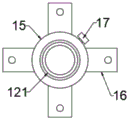
fig. 2 is a schematic view of a connection structure of a storage barrel, a sleeve b, a sleeve c and a connecting bolt in the novel building engineering formwork support device provided by the invention.
In the figure: 1. a base; 2. a rotating cylinder; 3. a bearing; 4. a U-shaped block; 5. a connecting rod; 6. a sleeve a; 7. a rotating shaft; 8. a fixed cylinder; 9. a screw rod; 10. a fixed block; 11. a connecting cylinder a; 12. a telescoping member; 121. a storage cylinder; 122. a connecting pipe a; 123. a connecting pipe b; 124. a connecting member; 13. a connecting cylinder b; 14. a support plate; 15. a sleeve b; 16. a sleeve c; 17. and connecting the bolts.
Detailed Description
The technical solutions in the embodiments of the present invention will be clearly and completely described below with reference to the drawings in the embodiments of the present invention, and it is obvious that the described embodiments are only a part of the embodiments of the present invention, and not all of the embodiments.
In the description of the present invention, it is to be understood that the terms "upper", "lower", "front", "rear", "left", "right", "top", "bottom", "inner", "outer", and the like, indicate orientations or positional relationships based on the orientations or positional relationships shown in the drawings, are merely for convenience in describing the present invention and simplifying the description, and do not indicate or imply that the device or element being referred to must have a particular orientation, be constructed and operated in a particular orientation, and thus, should not be construed as limiting the present invention.
Referring to fig. 1-2, a novel building engineering formwork supporting device comprises a base 1, wherein the top of the base 1 is rotatably connected with a rotating cylinder 2, a screw rod 9 is connected to the rotating cylinder 2 in a threaded manner, the rotating cylinder 2 is sleeved on the outer side wall of the screw rod 9 in a threaded manner, and the outer side wall of the top of the rotating cylinder 2 is connected with the top of the base 1 through a stabilizing mechanism;
the top of the screw rod 9 is detachably connected with an expansion piece 12, and the top of the expansion piece 12 is detachably connected with a supporting plate 14;
the telescopic member 12 comprises a receiving cylinder 121, the bottom and the top of the receiving cylinder 121 are respectively connected with a connecting pipe a122 and a connecting pipe b123 through a connecting member 124, and the receiving cylinder 121 is slidably sleeved on the outer side walls of the connecting pipe a122 and the connecting pipe b 123.
Wherein, the effect of rotating a section of thick bamboo 2, bearing 3, base 1 and solid fixed cylinder 8 is used for adjusting and rotates a section of thick bamboo 2 on base 1 for rotate a section of thick bamboo 2 and rotate the top that drives lead screw 9 and move from top to bottom on base 1, so that adjust the height of backup pad 14, realize supporting the engineering template of modelling.
More specifically, the base 1 is connected to the bottom of the rotary drum 2 through a bearing 3, and the base 1 is provided with a mounting groove corresponding to the bearing 3.
The bearing 3 is used for facilitating the rotation of the rotary drum 2 on the base 1, and meanwhile, the rotary drum 2 can be fixedly arranged on the base 1 to prevent the rotary drum 2 from falling off from the base 1.
More specifically, stabilizing mean including rotating sleeve a6 of cup jointing on a section of thick bamboo 2 top lateral wall that rotates, on the lateral wall of sleeve a6 and the equal fixedly connected with U type piece 4 in top of base 1, the 4 internal rotations of U type piece are connected with pivot 7, and two pivot 7 that correspond pass through connecting rod 5 and connect.
The stabilizing mechanism serves to improve the stability of the rotary drum 2 on top of the base 1.
More specifically, the top of the screw rod 9 is fixedly connected with a fixing block 10 which is arranged in a rectangular parallelepiped shape, the outer side wall of the fixing block 10 is slidably sleeved with a connecting tube a11, and the top of the connecting tube a11 is connected with the bottom of the connecting tube a 122.
The fixing block 10 and the connecting cylinder a11 are used for facilitating the connection of the screw rod 9 and the telescopic piece 12 and the installation and the disassembly between the screw rod 9 and the telescopic piece 12.
More specifically, the top of the connection tube b123 is connected to the bottom of the support plate 14 through the connection tube b13, and the connection tube b13 is connected to the connection tube b123 through the connection member 124. Facilitating the connection between the telescoping member 12 and the support plate 14 and facilitating the installation and removal of the support plate 14 from the telescoping member 12.
More specifically, the connector 124 comprises a bolt having a nut threaded onto one end of the bolt.
The connecting member 124 is used for fixing the receiving cylinder 121 to the connecting pipes a122 and b123, respectively, adjusting the length of the telescopic member 12, and fixedly connecting the connecting cylinder b13 to the top of the telescopic member 12.
More specifically, a fixed cylinder 8 is fixedly connected to the top outer sidewall of the rotary cylinder 2.
The effect of fixed section of thick bamboo 8 is convenient for insert and establishes reinforcing bar or steel pipe, and when reinforcing bar or steel pipe inserted the inside of establishing fixed section of thick bamboo 8, can act as the function of handle for rotate and rotate a section of thick bamboo 2 and rotate at the top of base 1, conveniently adjust the lift of backup pad 14.
More specifically, a sleeve b15 is fixedly connected to the outer side wall of the receiving cylinder 121, four sleeves c16 are fixedly connected to the outer side wall of the sleeve b15, and a screw hole is formed at the top of the sleeve c 16. So that two adjacent supporting devices are connected through the sleeve b15, the sleeve c16 and the steel pipe for connection, a plurality of supporting devices are connected to form a whole, and the stability of the supporting devices is improved.
More specifically, the sleeve b15 is connected to the housing tube 121 by the connecting bolt 17. It should be noted that a plurality of screw holes are provided on the outer side wall of the storage barrel 121, so as to adjust the position of the sleeve b15 and facilitate the connection of a plurality of supporting devices.
The working principle and the using process of the invention are as follows: when the supporting device is required to support the construction engineering template, the supporting plate 14 is firstly installed at the top of the telescopic part 12, then the length of the telescopic part 12 is adjusted, the base 1 is placed on the ground, the telescopic part 12 is installed at the top of the screw rod 9, then a steel bar or a steel pipe is inserted into the fixed cylinder 8, the rotating cylinder 2 is rotated, the top of the supporting plate 14 is adjusted to ascend until the top of the supporting plate 14 tightly supports against the construction engineering template, and finally two adjacent supporting devices are connected together by using the steel pipe for connection, so that the installation of the supporting device is completed. This strutting arrangement simple structure, length can be adjusted as required, and can dismantle, convenient operation, and in addition, adjacent strutting arrangement can interconnect together, and stability is good.
The above description is only for the preferred embodiment of the present invention, but the scope of the present invention is not limited thereto, and any person skilled in the art should be considered to be within the technical scope of the present invention, and the technical solutions and the inventive concepts thereof according to the present invention should be equivalent or changed within the scope of the present invention.
Claims (9)
1. The novel building engineering formwork supporting device comprises a base (1) and is characterized in that the top of the base (1) is rotatably connected with a rotating cylinder (2), a lead screw (9) is connected onto the rotating cylinder (2) in a threaded manner, the rotating cylinder (2) is sleeved on the outer side wall of the lead screw (9) in a threaded manner, and the outer side wall of the top of the rotating cylinder (2) is connected with the top of the base (1) through a stabilizing mechanism;
the top of the screw rod (9) is detachably connected with an expansion piece (12), and the top of the expansion piece (12) is detachably connected with a support plate (14);
the telescopic piece (12) comprises a containing barrel (121), the bottom and the top of the containing barrel (121) are respectively connected with a connecting pipe a (122) and a connecting pipe b (123) through a connecting piece (124), and the containing barrel (121) is sleeved on the outer side walls of the connecting pipe a (122) and the connecting pipe b (123) in a sliding mode.
2. The novel building engineering formwork supporting device is characterized in that the base (1) is connected with the bottom of the rotating cylinder (2) through a bearing (3), and a mounting groove corresponding to the bearing (3) is formed in the base (1).
3. The novel building engineering formwork support device according to claim 1, wherein the stabilizing mechanism comprises a sleeve a (6) rotatably sleeved on the outer side wall of the top of the rotating cylinder (2), the outer side wall of the sleeve a (6) and the top of the base (1) are fixedly connected with a U-shaped block (4), a rotating shaft (7) is rotatably connected in the U-shaped block (4), and the two corresponding rotating shafts (7) are connected through a connecting rod (5).
4. The novel building engineering formwork supporting device as claimed in claim 1, wherein a fixing block (10) in a rectangular parallelepiped shape is fixedly connected to the top of the screw rod (9), a connecting tube a (11) is slidably sleeved on the outer side wall of the fixing block (10), and the top of the connecting tube a (11) is connected to the bottom of the connecting tube a (122).
5. The novel form work support device of claim 1, wherein the top of the connection tube b (123) is connected with the bottom of the support plate (14) through a connection tube b (13), and the connection tube b (13) is connected with the connection tube b (123) through a connection member (124).
6. The novel form work support apparatus of claim 5, wherein the connector (124) comprises a bolt having a nut threadedly received at one end of the bolt.
7. The novel supporting device for the building engineering formwork according to claim 1 is characterized in that a fixed cylinder (8) is fixedly connected to the outer side wall of the top of the rotating cylinder (2).
8. The novel construction formwork support device according to claim 1, wherein a sleeve b (15) is fixedly connected to the outer side wall of the receiving cylinder (121), four sleeves c (16) are fixedly connected to the outer side wall of the sleeve b (15), and screw holes are formed in the tops of the sleeves c (16).
9. The new form support for construction work according to claim 1, characterized in that the sleeve b (15) is connected with the receiving cylinder (121) by means of a connecting bolt (17).
Priority Applications (1)
| Application Number | Priority Date | Filing Date | Title |
|---|---|---|---|
| CN202011413886.4A CN112627508A (en) | 2020-12-03 | 2020-12-03 | Novel building engineering formwork supports device |
Applications Claiming Priority (1)
| Application Number | Priority Date | Filing Date | Title |
|---|---|---|---|
| CN202011413886.4A CN112627508A (en) | 2020-12-03 | 2020-12-03 | Novel building engineering formwork supports device |
Publications (1)
| Publication Number | Publication Date |
|---|---|
| CN112627508A true CN112627508A (en) | 2021-04-09 |
Family
ID=75308114
Family Applications (1)
| Application Number | Title | Priority Date | Filing Date |
|---|---|---|---|
| CN202011413886.4A Pending CN112627508A (en) | 2020-12-03 | 2020-12-03 | Novel building engineering formwork supports device |
Country Status (1)
| Country | Link |
|---|---|
| CN (1) | CN112627508A (en) |
Cited By (1)
| Publication number | Priority date | Publication date | Assignee | Title |
|---|---|---|---|---|
| CN115559518A (en) * | 2022-10-18 | 2023-01-03 | 中铁九局集团第一建设有限公司 | Supporting device for special-shaped curved roof template and using method thereof |
-
2020
- 2020-12-03 CN CN202011413886.4A patent/CN112627508A/en active Pending
Cited By (1)
| Publication number | Priority date | Publication date | Assignee | Title |
|---|---|---|---|---|
| CN115559518A (en) * | 2022-10-18 | 2023-01-03 | 中铁九局集团第一建设有限公司 | Supporting device for special-shaped curved roof template and using method thereof |
Similar Documents
| Publication | Publication Date | Title |
|---|---|---|
| CN112627508A (en) | Novel building engineering formwork supports device | |
| CN113323409B (en) | Building assembled construction equipment | |
| CN211472518U (en) | Removable supporting is used in building engineering construction | |
| CN111719894A (en) | Post-cast strip supporting structure for civil house construction | |
| CN212613690U (en) | Flat iron type rigid wall connecting piece for building construction scaffold | |
| CN213654311U (en) | Detachable temporary supporting structure for building engineering | |
| CN214029623U (en) | Pipeline spare arrangement frame for building engineering | |
| CN112503339A (en) | Building surveyor's level is measured with adjusting supporting equipment | |
| CN217581215U (en) | Frame post template reinforcing apparatus is built in room | |
| CN218509002U (en) | Scaffold reinforcing and supporting structure for constructional engineering | |
| CN112900913A (en) | Auxiliary reinforcing device for building wall | |
| CN215978540U (en) | Brickwork mortar joint controlling means | |
| CN205649819U (en) | Wall -hanging hits target practice | |
| CN212642061U (en) | Scaffold frame that engineering construction operation was used is built in room | |
| CN210239323U (en) | Anti-seismic wall structure of green energy-saving building | |
| CN111042338A (en) | Foot margin device for folding house and adjusting method thereof | |
| CN210117664U (en) | Sound barrier convenient to equipment | |
| CN215168322U (en) | Adjustable anti-seismic reinforcing plate for constructional engineering | |
| CN218061822U (en) | Peripheral safety fence of engineering material mixing arrangement is built in municipal administration room | |
| CN220768984U (en) | Supporting device for construction of inner wall of assembled building | |
| CN204782060U (en) | Strutting arrangement for building site | |
| CN215491804U (en) | Building engineering environment monitoring device | |
| CN220036182U (en) | Pre-buried equipment of civil engineering construction | |
| CN220565777U (en) | Soil-shaped embedded steel pipe support frame | |
| CN219365355U (en) | Combined scaffold for constructional engineering |
Legal Events
| Date | Code | Title | Description |
|---|---|---|---|
| PB01 | Publication | ||
| PB01 | Publication |