CN112536015A - Multipurpose reation kettle is used in plasticizer processing production - Google Patents
Multipurpose reation kettle is used in plasticizer processing production Download PDFInfo
- Publication number
- CN112536015A CN112536015A CN202011519119.1A CN202011519119A CN112536015A CN 112536015 A CN112536015 A CN 112536015A CN 202011519119 A CN202011519119 A CN 202011519119A CN 112536015 A CN112536015 A CN 112536015A
- Authority
- CN
- China
- Prior art keywords
- lateral
- outer side
- longitudinal
- tank body
- reaction kettle
- Prior art date
- Legal status (The legal status is an assumption and is not a legal conclusion. Google has not performed a legal analysis and makes no representation as to the accuracy of the status listed.)
- Granted
Links
Images


Classifications
-
- B—PERFORMING OPERATIONS; TRANSPORTING
- B01—PHYSICAL OR CHEMICAL PROCESSES OR APPARATUS IN GENERAL
- B01J—CHEMICAL OR PHYSICAL PROCESSES, e.g. CATALYSIS OR COLLOID CHEMISTRY; THEIR RELEVANT APPARATUS
- B01J19/00—Chemical, physical or physico-chemical processes in general; Their relevant apparatus
- B01J19/18—Stationary reactors having moving elements inside
-
- B—PERFORMING OPERATIONS; TRANSPORTING
- B01—PHYSICAL OR CHEMICAL PROCESSES OR APPARATUS IN GENERAL
- B01J—CHEMICAL OR PHYSICAL PROCESSES, e.g. CATALYSIS OR COLLOID CHEMISTRY; THEIR RELEVANT APPARATUS
- B01J19/00—Chemical, physical or physico-chemical processes in general; Their relevant apparatus
- B01J19/0053—Details of the reactor
-
- B—PERFORMING OPERATIONS; TRANSPORTING
- B01—PHYSICAL OR CHEMICAL PROCESSES OR APPARATUS IN GENERAL
- B01J—CHEMICAL OR PHYSICAL PROCESSES, e.g. CATALYSIS OR COLLOID CHEMISTRY; THEIR RELEVANT APPARATUS
- B01J4/00—Feed or outlet devices; Feed or outlet control devices
- B01J4/001—Feed or outlet devices as such, e.g. feeding tubes
-
- B—PERFORMING OPERATIONS; TRANSPORTING
- B02—CRUSHING, PULVERISING, OR DISINTEGRATING; PREPARATORY TREATMENT OF GRAIN FOR MILLING
- B02C—CRUSHING, PULVERISING, OR DISINTEGRATING IN GENERAL; MILLING GRAIN
- B02C18/00—Disintegrating by knives or other cutting or tearing members which chop material into fragments
- B02C18/06—Disintegrating by knives or other cutting or tearing members which chop material into fragments with rotating knives
- B02C18/08—Disintegrating by knives or other cutting or tearing members which chop material into fragments with rotating knives within vertical containers
- B02C18/10—Disintegrating by knives or other cutting or tearing members which chop material into fragments with rotating knives within vertical containers with drive arranged above container
-
- B—PERFORMING OPERATIONS; TRANSPORTING
- B02—CRUSHING, PULVERISING, OR DISINTEGRATING; PREPARATORY TREATMENT OF GRAIN FOR MILLING
- B02C—CRUSHING, PULVERISING, OR DISINTEGRATING IN GENERAL; MILLING GRAIN
- B02C18/00—Disintegrating by knives or other cutting or tearing members which chop material into fragments
- B02C18/06—Disintegrating by knives or other cutting or tearing members which chop material into fragments with rotating knives
- B02C18/16—Details
- B02C18/18—Knives; Mountings thereof
-
- B—PERFORMING OPERATIONS; TRANSPORTING
- B01—PHYSICAL OR CHEMICAL PROCESSES OR APPARATUS IN GENERAL
- B01J—CHEMICAL OR PHYSICAL PROCESSES, e.g. CATALYSIS OR COLLOID CHEMISTRY; THEIR RELEVANT APPARATUS
- B01J2204/00—Aspects relating to feed or outlet devices; Regulating devices for feed or outlet devices
- B01J2204/005—Aspects relating to feed or outlet devices; Regulating devices for feed or outlet devices the outlet side being of particular interest
Landscapes
- Chemical & Material Sciences (AREA)
- Organic Chemistry (AREA)
- Chemical Kinetics & Catalysis (AREA)
- Engineering & Computer Science (AREA)
- Food Science & Technology (AREA)
- Mixers Of The Rotary Stirring Type (AREA)
- Physical Or Chemical Processes And Apparatus (AREA)
Abstract
The invention relates to the technical field of plasticizer processing production, in particular to a multipurpose reaction kettle for plasticizer processing production. According to the multipurpose reaction kettle for processing and producing the plasticizer, the longitudinal transmission pipe internally provided with the internal lifting rod is arranged in the main tank body, the bottom filtering frame and the longitudinal material guiding screen frame which are communicated are arranged on the outer side of the longitudinal transmission pipe, materials are guided into the bottom filtering frame from the longitudinal material guiding screen frame to facilitate the reaction of additives in different forms, and the multipurpose reaction kettle is more convenient to use; the angle of the stirring blade is changed by lifting, so that large-particle matters in the bottom filtering frame can be crushed as required, mixed liquid in the reaction kettle can be stirred, and internal filtered matters can be squeezed and discharged, the control is simple and convenient, and the production efficiency is greatly improved; the filtering capacity is adjustable, and the application range is wider; the deslagging operation is simple and convenient.
Description
Technical Field
The invention relates to the technical field of plasticizer processing production, in particular to a multipurpose reaction kettle for plasticizer processing production.
Background
Plasticizers are additives for polymer materials, which are widely used in industrial production, and are also called plasticizers. Any substance added to a polymeric material that increases the plasticity of the polymer is called a plasticizer. The plasticizer can improve the performance of the high polymer material, reduce the production cost and improve the production benefit. The phthalate ester is an important chemical product additive, is generally applied to materials such as plastic products, concrete, mud ash, cement, gypsum, cosmetics, cleaning agents and the like as an auxiliary agent, particularly polyvinyl chloride plastic products, and is required to be added in order to increase the plasticity of the plastic and improve the strength of the plastic, and the content of the phthalate ester can sometimes reach 50 percent of the product. The plasticizer mainly has the effects of weakening the secondary valence bonds among resin molecules, increasing the mobility of the molecular bonds of the resin, reducing the crystallinity of the resin molecules, increasing the plasticity of the resin molecules, enhancing the flexibility of the resin molecules, being easy to process, being legally applicable to industrial application, and being widely existed in food packaging, cosmetics, medical devices and environmental water. Such as cling film, food packaging, toys, etc.
Plasticizer need apply to reation kettle in the processing production process, traditional reation kettle simple structure, and reaction mode is single, simultaneously because reation kettle's structure is fixed, can't adjust as required, leads to its functional relatively more single, advances to arrange the material mode single moreover, and production efficiency is not high.
Disclosure of Invention
The technical problem to be solved by the invention is as follows: in order to solve the problem that exists among the above-mentioned background art, provide a multipurpose reation kettle is used in plasticizer processing production of modified, solve the tradition and be used for the reation kettle simple structure of plasticizer processing, the reaction mode is single, simultaneously because reation kettle's fixed structure, can't adjust as required, lead to its functional relatively single, advance moreover and arrange the material mode single, problem that production efficiency is not high.
The technical scheme adopted by the invention for solving the technical problems is as follows: a multipurpose reaction kettle for processing and producing a plasticizer comprises a main tank body, an electric control hydraulic lifter and an adjusting motor, wherein a longitudinal transmission pipe is arranged at the center position inside the main tank body, a bottom filter frame is fixedly connected to the center position of the inner bottom surface of the main tank body, an inner lifting rod is arranged inside the longitudinal transmission pipe, a longitudinal lifting port is arranged inside the bottom filter frame on the outer side surface of the longitudinal transmission pipe, a lateral assembly shaft and a lateral linkage rod protruding towards the longitudinal lifting port are arranged on the outer side surface of the inner lifting rod, a stirring blade is movably sleeved outside the lateral assembly shaft, a lateral assembly groove with a built-in detachable crushing blade is arranged at the edge position of the outer side surface of the stirring blade, a longitudinal guide screen frame communicated with the inside of the bottom filter frame is fixedly connected to the outer side of the longitudinal transmission pipe inside the main tank body, the inner side surface of the bottom filter frame is movably connected with an inner adjusting filter ring, the upper end of the inner side surface of the inner adjusting filter ring is fixedly connected with an outer assembling disc, and the outer side surface of the lateral linkage rod is fixedly connected with an inner linkage cover matched with the outer assembling disc.
The outer side surface of the longitudinal transmission pipe is positioned at an opening position at the outer side of the longitudinal lifting port and is provided with a lateral transmission rack in an integrated structure, and a lateral transmission gear ring meshed with the lateral transmission rack is axially fixed at the inner side connecting end of the outer side surface of the stirring blade.
The outer side surface of the longitudinal transmission pipe is positioned at the top end of the main tank body, an overhead gear transmission set in transmission connection with a lateral rotating shaft of an adjusting motor is axially fixed on the outer side surface of the longitudinal transmission pipe, and the top end of the main tank body is fixedly connected with a top mounting support for mounting an electric control hydraulic elevator through bolts.
The upper end of the main tank body is fixedly welded with a plurality of external feeding pipes, and an internal arc-shaped feeding pipe is fixedly connected between the longitudinal feeding net frame and the external feeding pipes inside the main tank body.
The main jar of body bottom be located the inside a plurality of arc bin outlets of having seted up of bottom filter frame, main jar of body bottom central point put the bottom adjustment hole of seting up built-in regulating block, the regulating block lateral surface on fixedly connected with be used for the lateral seal board of closed arc bin outlet, regulating block upper end seted up hexagon socket head cap regulating control blind hole, inside lifter bottom axial be fixed with should have outer hexagonal control shaft, the arc bin outlet be the edge position in the filter frame of bottom of annular array mode range.
And a lateral clamping frame for improving the sealing performance of the lateral sealing plate is fixedly welded on the outer side surface of the arc-shaped discharge opening on the bottom surface of the main tank body.
The cross section of the outer side surface of the inner lifting rod is of a non-circular structure, and no gap exists between the outer side surface of the inner lifting rod and the inner connecting surface of the longitudinal transmission pipe.
The invention has the beneficial effects that:
(1) according to the multipurpose reaction kettle for processing and producing the plasticizer, the longitudinal transmission pipe internally provided with the internal lifting rod is arranged in the main tank body, the bottom filtering frame and the longitudinal material guiding screen frame which are communicated are arranged on the outer side of the longitudinal transmission pipe, materials are guided into the bottom filtering frame from the longitudinal material guiding screen frame to facilitate the reaction of additives in different forms, and the multipurpose reaction kettle is more convenient to use;
(2) the lifting of the inner lifting rod is controlled by the electric control hydraulic lifter, the outer side of the lateral assembling shaft outside the inner lifting rod is movably sleeved with the stirring blade with the adjustable angle, and the angle of the stirring blade is changed by lifting, so that large-particle substances inside the bottom filtering frame can be crushed as required, mixed liquid in the reaction kettle can be stirred, the inner filtering substances can be squeezed and separated, the control is simple and convenient, and the production efficiency is greatly improved;
(3) an internal adjusting filter ring is arranged on the inner side of the bottom filter frame, and the internal adjusting filter ring is driven to lift through a lateral linkage rod on the outer side of an internal lifting rod, so that the size of a filter hole is changed, the filtering capacity of the filter hole is adjustable, and the application range is wider;
(4) the bottom of the main tank body is positioned in the bottom of the filter frame, an arc discharge hole with a bottom lateral sealing plate is formed in the bottom of the filter frame, an inner hexagonal adjusting and controlling blind hole is inserted by an outer hexagonal control shaft at the bottom of the inner lifting rod to control the lateral sealing plate, and the deslagging operation is simple and convenient.
Drawings
The invention is further illustrated with reference to the following figures and examples.
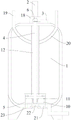
Fig. 1 is a schematic structural view of the present invention.
Fig. 2 is a structural sectional view of the inside of the bottom filter frame in the present invention.
Fig. 3 is a schematic diagram of the position of the overhead gear train of the present invention.
Detailed Description
The present invention will now be described in further detail with reference to the accompanying drawings. These drawings are simplified schematic views illustrating only the basic structure of the present invention in a schematic manner, and thus show only the constitution related to the present invention.
The multipurpose reaction kettle for processing and producing the plasticizer, which is shown in the figures 1, 2 and 3, comprises a main tank body 1, an electric control hydraulic lifter 2 and an adjusting motor 3, wherein a longitudinal transmission pipe 4 is arranged at the center position in the main tank body 1, a bottom filter frame 5 is fixedly connected at the center position of the inner bottom surface in the main tank body 1, an inner lifting rod 6 is arranged in the longitudinal transmission pipe 4, a longitudinal lifting port 7 is formed in the bottom filter frame 5 on the outer side surface of the longitudinal transmission pipe 4, a lateral assembly shaft 8 protruding towards the longitudinal lifting port 7 and a lateral linkage rod 9 are arranged on the outer side surface of the inner lifting rod 6, a stirring blade 10 is movably sleeved on the outer side of the lateral assembly shaft 8, a lateral assembly groove with a detachable crushing blade 11 is formed in the edge position of the outer side surface of the stirring blade 10, the crushing blade 11 is fixed in the lateral assembly groove, the inside of the main tank body 1 is positioned outside the longitudinal transmission pipe 4 and is fixedly connected with a longitudinal material guide screen frame 12 communicated with the inside of the bottom filter frame 5, the inner side surface of the bottom filter frame 5 is movably connected with an inner adjusting filter ring 13, the upper end of the inner side surface of the inner adjusting filter ring 13 is fixedly connected with an outer assembly disc 14, and the outer side surface of the lateral linkage rod 9 is fixedly connected with an inner linkage cover 15 matched with the outer assembly disc 14.
Example (b): the telescopic rod at the lower end of the electric control hydraulic lifter 2 is connected with the top end of the inner lifting rod 6 in an inserting manner, and the lateral limiting block is arranged on the outer lateral surface of the telescopic rod at the lower end of the electric control hydraulic lifter 2 and used for conveniently controlling the lifting of the inner lifting rod 6.
Further, in order to match with transmission control, an integral lateral transmission rack 16 is arranged at the position, located at the opening of the outer side of the longitudinal lifting port 7, of the outer side of the longitudinal transmission pipe 4, a lateral transmission toothed ring 17 meshed with the lateral transmission rack 16 is axially fixed at the inner side connecting end of the outer side of the stirring blade 10, further, in order to match with top transmission and installation, an overhead gear transmission set in transmission connection with a lateral rotating shaft of the adjusting motor 3 is axially fixed at the top end of the main tank body 1 of the outer side of the longitudinal transmission pipe 4, and the top end of the main tank body 1 is fixedly connected with a top installation support 18 used for installing the electric control hydraulic lifter 2 through bolts.
Example (b): the inner lifting rod 6 drives the lateral transmission toothed ring 17 to rotate through lifting, so that the stirring blade 10 is controlled to turn over, and when the stirring blade 10 is vertical, the stirring blade is used for stirring; when the stirring blade 10 is horizontal, the cutting purpose is realized; when the stirring blades are inclined, the extrusion discharging application is realized.
Further, for cooperation feeding and inside guide, main jar of body 1 upper end fixed welding has 2 outside inlet pipes 19, main jar of body 1 is inside to be located the inside arc passage 20 of fixedly connected with between vertical guide screen frame 12 and the outside inlet pipe 19, further, arrange material and coordinated control for the cooperation, main jar of body 1 bottom is located bottom filter frame 5 inside has seted up 2 arc bin outlet 21, main jar of body 1 bottom central point puts the bottom regulation hole of seting up built-in regulating block 22, fixedly connected with is used for the lateral seal board 23 of closed arc bin outlet 21 on the regulating block 22 lateral surface, interior hexagonal regulation control blind hole has been seted up to the regulating block 22 upper end, 6 bottom axial fixings of inside lifter should have outer hexagonal control shaft 24, arc bin outlet 21 is the edge position in bottom filter frame 5 of circular array mode range.
Further, in order to improve the bottom sealing performance, a lateral clamping frame 25 for improving the sealing performance of a lateral sealing plate 23 is fixedly welded on the bottom surface of the main tank body 1 on the outer side surface of the arc-shaped discharge opening 21, further, in order to match with linkage control, the cross section of the outer side surface of the inner lifting rod 6 is of a non-circular structure, and no gap exists between the outer side surface of the inner lifting rod 6 and the inner connecting surface of the longitudinal transmission pipe 4.
According to the multipurpose reaction kettle for processing and producing the plasticizer, the longitudinal transmission pipe 4 with the built-in internal lifting rod 6 is arranged in the main tank body 1, the bottom filtering frame 5 and the longitudinal material guiding screen frame 12 which are communicated with each other are arranged on the outer side of the longitudinal transmission pipe 4, materials are guided into the bottom filtering frame 5 from the longitudinal material guiding screen frame 12 to facilitate the reaction of additives with different forms, and the multipurpose reaction kettle is more convenient to use; the lifting of the inner lifting rod 6 is controlled by the electric control hydraulic lifter 2, the stirring blade 10 with the adjustable angle is movably sleeved outside the lateral assembling shaft 8 outside the inner lifting rod 6, and the angle of the stirring blade 10 is changed by lifting, so that large particles inside the bottom filtering frame 5 can be crushed as required, mixed liquid in the reaction kettle can be stirred, the inner filtering object can be squeezed and separated, the control is simple and convenient, and the production efficiency is greatly improved; an internal adjusting filter ring 13 is arranged on the inner side of the bottom filter frame 5, and the internal adjusting filter ring 13 is driven to lift through a lateral linkage rod 9 on the outer side of the internal lifting rod 6, so that the size of a filter hole is changed, the filtering capacity of the filter hole is adjustable, and the application range is wider; the bottom end of the main tank body 1 is positioned in the bottom filter frame 5 and is internally provided with an arc discharge outlet 21 with a bottom lateral sealing plate 23, an outer hexagonal control shaft 24 at the bottom of the inner lifting rod 6 is inserted into the inner hexagonal adjusting control blind hole to control the lateral sealing plate 23, and the deslagging operation is simple and convenient.
In light of the foregoing description of the preferred embodiment of the present invention, many modifications and variations will be apparent to those skilled in the art without departing from the spirit and scope of the invention. The technical scope of the present invention is not limited to the content of the specification, and must be determined according to the scope of the claims.
Claims (7)
1. The utility model provides a multipurpose reation kettle is used in plasticizer processing production, includes main jar body (1), automatically controlled hydraulic lift (2) and accommodate motor (3), characterized by: the main tank body (1) is internally provided with a longitudinal transmission pipe (4) at the center, the main tank body (1) is fixedly connected with a bottom filter frame (5) at the center of the inner bottom surface, an internal lifting rod (6) is arranged inside the longitudinal transmission pipe (4), the outer side surface of the longitudinal transmission pipe (4) is positioned inside the bottom filter frame (5) and is provided with a longitudinal lifting port (7), the outer side surface of the internal lifting rod (6) is provided with a lateral assembly shaft (8) and a lateral linkage rod (9) which protrude towards the longitudinal lifting port (7), the outer side of the lateral assembly shaft (8) is movably sleeved with a stirring blade (10), the edge position of the outer side surface of the stirring blade (10) is provided with a lateral assembly groove internally provided with a detachable crushing blade (11), the main tank body (1) is internally positioned outside the longitudinal transmission pipe (4) and is fixedly connected with a longitudinal material guide screen frame (12) communicated with the inside of the bottom filter frame (5, the inner side surface of the bottom filter frame (5) is movably connected with an inner adjusting filter ring (13), the upper end of the inner side surface of the inner adjusting filter ring (13) is fixedly connected with an outer assembling disc (14), and the outer side surface of the lateral linkage rod (9) is fixedly connected with an inner linkage cover (15) matched with the outer assembling disc (14).
2. The multi-purpose reaction kettle for processing and producing the plasticizer according to claim 1, which is characterized in that: the lateral surface of the longitudinal transmission pipe (4) is positioned at the opening position at the outer side of the longitudinal lifting port (7) and is provided with a lateral transmission rack (16) with an integrated structure, and the lateral surface of the stirring blade (10) is positioned at the inner side connecting end and is axially fixed with a lateral transmission toothed ring (17) meshed with the lateral transmission rack (16).
3. The multi-purpose reaction kettle for processing and producing the plasticizer according to claim 1, which is characterized in that: the lateral surface of the longitudinal transmission pipe (4) is positioned at the top end of the main tank body (1) and is axially fixed with an overhead gear transmission set in transmission connection with a lateral rotating shaft of the adjusting motor (3), and the top end of the main tank body (1) is fixedly connected with a top mounting bracket (18) used for mounting the electric control hydraulic elevator (2) through bolts.
4. The multi-purpose reaction kettle for processing and producing the plasticizer according to claim 1, which is characterized in that: the feed tank is characterized in that a plurality of external feed pipes (19) are fixedly welded at the upper end of the main tank body (1), and an internal arc-shaped feed pipe (20) is fixedly connected between the vertical feed guiding net frame (12) and the external feed pipes (19) inside the main tank body (1).
5. The multi-purpose reaction kettle for processing and producing the plasticizer according to claim 1, which is characterized in that: the main jar of body (1) bottom be located the inside a plurality of arc bin outlet (21) of having seted up of bottom filter frame (5), the main jar of body (1) bottom central point put the bottom adjustment hole of seting up built-in regulating block (22), regulating block (22) lateral surface on fixedly connected with be used for side direction closing plate (24) of closed arc bin outlet (21), regulating block (22) upper end seted up interior hexagonal regulation control blind hole, inside lifter (6) bottom axial fixity should have outer hexagonal control shaft (25), arc bin outlet (21) be the edge position in annular array mode range filter frame (5) in the bottom.
6. The multi-purpose reaction kettle for processing and producing the plasticizer according to claim 5, wherein: and a lateral clamping frame (26) for improving the sealing performance of a lateral sealing plate (24) is fixedly welded on the outer side surface of the arc discharge opening (21) on the bottom surface of the main tank body (1).
7. The multi-purpose reaction kettle for processing and producing the plasticizer according to claim 1, which is characterized in that: the cross section of the outer side surface of the inner lifting rod (6) is of a non-circular structure, and no gap exists between the outer side surface of the inner lifting rod (6) and the inner connecting surface of the longitudinal transmission pipe (4).
Priority Applications (1)
| Application Number | Priority Date | Filing Date | Title |
|---|---|---|---|
| CN202011519119.1A CN112536015B (en) | 2020-12-21 | 2020-12-21 | Multipurpose reation kettle is used in plasticizer processing production |
Applications Claiming Priority (1)
| Application Number | Priority Date | Filing Date | Title |
|---|---|---|---|
| CN202011519119.1A CN112536015B (en) | 2020-12-21 | 2020-12-21 | Multipurpose reation kettle is used in plasticizer processing production |
Publications (2)
| Publication Number | Publication Date |
|---|---|
| CN112536015A true CN112536015A (en) | 2021-03-23 |
| CN112536015B CN112536015B (en) | 2022-06-24 |
Family
ID=75019326
Family Applications (1)
| Application Number | Title | Priority Date | Filing Date |
|---|---|---|---|
| CN202011519119.1A Active CN112536015B (en) | 2020-12-21 | 2020-12-21 | Multipurpose reation kettle is used in plasticizer processing production |
Country Status (1)
| Country | Link |
|---|---|
| CN (1) | CN112536015B (en) |
Cited By (2)
| Publication number | Priority date | Publication date | Assignee | Title |
|---|---|---|---|---|
| CN114470905A (en) * | 2022-02-09 | 2022-05-13 | 深圳市格盛力能源有限公司 | Slurry filtering device for lithium battery production |
| CN115282916A (en) * | 2022-10-10 | 2022-11-04 | 江苏旭阳化工设备有限公司 | Chemical industry reation kettle of high leakproofness |
Citations (22)
| Publication number | Priority date | Publication date | Assignee | Title |
|---|---|---|---|---|
| NL1009059C2 (en) * | 1998-05-04 | 1999-11-05 | Pelleting Technology Nederland | Mixer for e.g. homogenizing granular or powdered products |
| US20020020663A1 (en) * | 2000-08-17 | 2002-02-21 | Carew E. Bayne | Filter assembly, filter element, and method of utilizing the same |
| CN101157615A (en) * | 2007-10-31 | 2008-04-09 | 无锡双象化学工业有限公司 | Method for producing plasticizer phthalic acid dinonyl |
| CN101837311A (en) * | 2010-03-19 | 2010-09-22 | 海盐机械厂 | Hammer for reversible hammer crusher |
| JP2011161315A (en) * | 2010-02-05 | 2011-08-25 | Panasonic Corp | Coating apparatus |
| CN106237685A (en) * | 2016-09-21 | 2016-12-21 | 东莞市联洲知识产权运营管理有限公司 | A kind of sewage disposal device |
| CN206253073U (en) * | 2016-11-21 | 2017-06-16 | 曹勃 | A kind of moveable mixing equipment with filtering function |
| CN206509063U (en) * | 2017-01-16 | 2017-09-22 | 广州市百森装饰材料有限公司 | A kind of vertical beater with damping and deslagging function |
| CN207187656U (en) * | 2017-08-30 | 2018-04-06 | 上海保兴生物设备工程有限公司 | A kind of mixing apparatus of pharmaceutical purpose |
| CN207287275U (en) * | 2017-09-06 | 2018-05-01 | 山东农业大学 | A kind of comminuting dasher |
| CN108371930A (en) * | 2018-03-21 | 2018-08-07 | 无锡宝丰石化装备有限公司 | A kind of sieving formula reaction kettle |
| CN108783543A (en) * | 2018-06-22 | 2018-11-13 | 河南金土商贸有限公司 | A kind of Feed Manufacturing crushing stirring integration machine |
| CN208177563U (en) * | 2018-01-29 | 2018-12-04 | 上海兆捷实业发展有限公司 | A kind of agitating shaft for planetary mixer |
| CN208406751U (en) * | 2018-03-30 | 2019-01-22 | 伟大集团节能房股份有限公司 | A kind of mould wash mixer |
| CN208694954U (en) * | 2018-09-04 | 2019-04-05 | 江西峰竺新材料科技有限公司 | A kind of reaction kettle preparing calcium sulfate crystal whiskers |
| CN208906128U (en) * | 2018-08-21 | 2019-05-28 | 山东农合生物科技有限公司 | A kind of organic fertilizer quick crashing device |
| CN209680037U (en) * | 2019-01-30 | 2019-11-26 | 广东两山科技有限公司 | Batch mixer |
| CN210303515U (en) * | 2019-06-12 | 2020-04-14 | 上海彩谷新材料科技有限公司 | Mixed raw material preparation device for chemical production |
| CN210545721U (en) * | 2019-07-08 | 2020-05-19 | 江苏沃田集团股份有限公司 | Centrifugal device of anthocyanin production usefulness |
| CN210543549U (en) * | 2019-09-10 | 2020-05-19 | 浙江伟博化工科技有限公司 | Plasticizer is quick filter equipment for continuous production |
| CN112871118A (en) * | 2021-01-20 | 2021-06-01 | 江苏福昌环保科技集团有限公司 | Reation kettle with adjustable plasticizer processing production is with structure |
| CN214183088U (en) * | 2020-12-16 | 2021-09-14 | 都江堰市千乙生物科技有限公司 | Reation kettle is used in heisui river horsefly feed processing |
-
2020
- 2020-12-21 CN CN202011519119.1A patent/CN112536015B/en active Active
Patent Citations (22)
| Publication number | Priority date | Publication date | Assignee | Title |
|---|---|---|---|---|
| NL1009059C2 (en) * | 1998-05-04 | 1999-11-05 | Pelleting Technology Nederland | Mixer for e.g. homogenizing granular or powdered products |
| US20020020663A1 (en) * | 2000-08-17 | 2002-02-21 | Carew E. Bayne | Filter assembly, filter element, and method of utilizing the same |
| CN101157615A (en) * | 2007-10-31 | 2008-04-09 | 无锡双象化学工业有限公司 | Method for producing plasticizer phthalic acid dinonyl |
| JP2011161315A (en) * | 2010-02-05 | 2011-08-25 | Panasonic Corp | Coating apparatus |
| CN101837311A (en) * | 2010-03-19 | 2010-09-22 | 海盐机械厂 | Hammer for reversible hammer crusher |
| CN106237685A (en) * | 2016-09-21 | 2016-12-21 | 东莞市联洲知识产权运营管理有限公司 | A kind of sewage disposal device |
| CN206253073U (en) * | 2016-11-21 | 2017-06-16 | 曹勃 | A kind of moveable mixing equipment with filtering function |
| CN206509063U (en) * | 2017-01-16 | 2017-09-22 | 广州市百森装饰材料有限公司 | A kind of vertical beater with damping and deslagging function |
| CN207187656U (en) * | 2017-08-30 | 2018-04-06 | 上海保兴生物设备工程有限公司 | A kind of mixing apparatus of pharmaceutical purpose |
| CN207287275U (en) * | 2017-09-06 | 2018-05-01 | 山东农业大学 | A kind of comminuting dasher |
| CN208177563U (en) * | 2018-01-29 | 2018-12-04 | 上海兆捷实业发展有限公司 | A kind of agitating shaft for planetary mixer |
| CN108371930A (en) * | 2018-03-21 | 2018-08-07 | 无锡宝丰石化装备有限公司 | A kind of sieving formula reaction kettle |
| CN208406751U (en) * | 2018-03-30 | 2019-01-22 | 伟大集团节能房股份有限公司 | A kind of mould wash mixer |
| CN108783543A (en) * | 2018-06-22 | 2018-11-13 | 河南金土商贸有限公司 | A kind of Feed Manufacturing crushing stirring integration machine |
| CN208906128U (en) * | 2018-08-21 | 2019-05-28 | 山东农合生物科技有限公司 | A kind of organic fertilizer quick crashing device |
| CN208694954U (en) * | 2018-09-04 | 2019-04-05 | 江西峰竺新材料科技有限公司 | A kind of reaction kettle preparing calcium sulfate crystal whiskers |
| CN209680037U (en) * | 2019-01-30 | 2019-11-26 | 广东两山科技有限公司 | Batch mixer |
| CN210303515U (en) * | 2019-06-12 | 2020-04-14 | 上海彩谷新材料科技有限公司 | Mixed raw material preparation device for chemical production |
| CN210545721U (en) * | 2019-07-08 | 2020-05-19 | 江苏沃田集团股份有限公司 | Centrifugal device of anthocyanin production usefulness |
| CN210543549U (en) * | 2019-09-10 | 2020-05-19 | 浙江伟博化工科技有限公司 | Plasticizer is quick filter equipment for continuous production |
| CN214183088U (en) * | 2020-12-16 | 2021-09-14 | 都江堰市千乙生物科技有限公司 | Reation kettle is used in heisui river horsefly feed processing |
| CN112871118A (en) * | 2021-01-20 | 2021-06-01 | 江苏福昌环保科技集团有限公司 | Reation kettle with adjustable plasticizer processing production is with structure |
Non-Patent Citations (4)
| Title |
|---|
| 何琼儒: "《转位刀具》", 31 January 1980, 西安:陕西科学技术出版社, pages: 10 - 11 * |
| 张瑞志: "《高分子材料生产加工设备》", 30 April 1994, 北京:中国纺织出版社, pages: 2 - 3 * |
| 杨志才: "《化工生产中的间歇过程 原理、工艺及设备》", 30 June 2001, 北京:化学工业出版社, pages: 127 - 130 * |
| 湖南省革命委员会国防工业办公室等: "《机夹刀具》", 30 April 1977, 长沙:湖南人民出版社, pages: 62 * |
Cited By (2)
| Publication number | Priority date | Publication date | Assignee | Title |
|---|---|---|---|---|
| CN114470905A (en) * | 2022-02-09 | 2022-05-13 | 深圳市格盛力能源有限公司 | Slurry filtering device for lithium battery production |
| CN115282916A (en) * | 2022-10-10 | 2022-11-04 | 江苏旭阳化工设备有限公司 | Chemical industry reation kettle of high leakproofness |
Also Published As
| Publication number | Publication date |
|---|---|
| CN112536015B (en) | 2022-06-24 |
Similar Documents
| Publication | Publication Date | Title |
|---|---|---|
| CN112536015B (en) | Multipurpose reation kettle is used in plasticizer processing production | |
| CN214810403U (en) | Raw material mixing device is used in bio-organic fertilizer production | |
| CN210332486U (en) | Drag reducer synthesis production device for oil well cement | |
| CN112871118B (en) | Reation kettle with adjustable plasticizer processing production is with structure | |
| CN116550210A (en) | Efficient mixing device for aquatic animal feed production | |
| CN112546998A (en) | Plasticizer processing production reation kettle | |
| CN214131217U (en) | Plant fiber board production is with rotatory agitating unit | |
| CN216224341U (en) | Chemical industry reation kettle of easily fully adding catalyst | |
| CN215388842U (en) | Stirrer for waste recovery | |
| CN210415001U (en) | Novel building material production stir device | |
| CN2787408Y (en) | Multiple-material once mixing machine | |
| CN210734543U (en) | Multifunctional stirring reaction and filling device for structural adhesive production | |
| CN110270287B (en) | Reaction kettle device for high-performance polyphenylene sulfide composite material | |
| CN220638531U (en) | PE tubular product raw materials compounding device | |
| CN219424234U (en) | Energy-conserving mixer of sealant | |
| CN221292199U (en) | Be applied to feed hopper structure on tubular product extruder | |
| CN221662939U (en) | High-efficient fermenting installation | |
| CN208022059U (en) | A kind of sealed type pressure storage tank | |
| CN110142019B (en) | RTV electronic adhesive serial reaction kettle and production method | |
| CN220276825U (en) | Powder material stirring device | |
| CN221359388U (en) | Automatic mixing device for modified starch processing | |
| CN212417650U (en) | Wet mixing granulator capable of preventing slurry from sticking to wall | |
| CN215693936U (en) | High-efficient synthetic cauldron of dicyanate | |
| CN211443884U (en) | Anti-blocking spiral material conveying machine | |
| CN218488817U (en) | Blendor is used in plastic products production with prevent outer function that spatters |
Legal Events
| Date | Code | Title | Description |
|---|---|---|---|
| PB01 | Publication | ||
| PB01 | Publication | ||
| SE01 | Entry into force of request for substantive examination | ||
| SE01 | Entry into force of request for substantive examination | ||
| TA01 | Transfer of patent application right |
Effective date of registration: 20210820 Address after: 225400 Taixing Economic Development Zone, Taizhou City, Jiangsu Province Applicant after: TAIXING FUCHANG ENVIRONMENTAL PROTECTION TECHNOLOGY Co.,Ltd. Address before: 213000 Beihu village, Henglin Town, Wujin District, Changzhou City, Jiangsu Province Applicant before: JIANGSU FUCHANG ENVIRONMENT PROTECTION TECHNOLOGYGROUP Co.,Ltd. |
|
| TA01 | Transfer of patent application right | ||
| GR01 | Patent grant | ||
| GR01 | Patent grant |