CN112520130A - Ceramic membrane production system - Google Patents
Ceramic membrane production system Download PDFInfo
- Publication number
- CN112520130A CN112520130A CN202011258217.4A CN202011258217A CN112520130A CN 112520130 A CN112520130 A CN 112520130A CN 202011258217 A CN202011258217 A CN 202011258217A CN 112520130 A CN112520130 A CN 112520130A
- Authority
- CN
- China
- Prior art keywords
- rod
- plate
- cylinder
- fixing
- supporting
- Prior art date
- Legal status (The legal status is an assumption and is not a legal conclusion. Google has not performed a legal analysis and makes no representation as to the accuracy of the status listed.)
- Granted
Links
Images


Classifications
-
- B—PERFORMING OPERATIONS; TRANSPORTING
- B65—CONVEYING; PACKING; STORING; HANDLING THIN OR FILAMENTARY MATERIAL
- B65B—MACHINES, APPARATUS OR DEVICES FOR, OR METHODS OF, PACKAGING ARTICLES OR MATERIALS; UNPACKING
- B65B51/00—Devices for, or methods of, sealing or securing package folds or closures; Devices for gathering or twisting wrappers, or necks of bags
- B65B51/10—Applying or generating heat or pressure or combinations thereof
- B65B51/14—Applying or generating heat or pressure or combinations thereof by reciprocating or oscillating members
-
- B—PERFORMING OPERATIONS; TRANSPORTING
- B65—CONVEYING; PACKING; STORING; HANDLING THIN OR FILAMENTARY MATERIAL
- B65B—MACHINES, APPARATUS OR DEVICES FOR, OR METHODS OF, PACKAGING ARTICLES OR MATERIALS; UNPACKING
- B65B61/00—Auxiliary devices, not otherwise provided for, for operating on sheets, blanks, webs, binding material, containers or packages
- B65B61/04—Auxiliary devices, not otherwise provided for, for operating on sheets, blanks, webs, binding material, containers or packages for severing webs, or for separating joined packages
- B65B61/06—Auxiliary devices, not otherwise provided for, for operating on sheets, blanks, webs, binding material, containers or packages for severing webs, or for separating joined packages by cutting
Abstract
The invention discloses a ceramic membrane production system which comprises a bagging device, wherein the bagging device comprises a rack, a cloth conveying mechanism, a discharging mechanism, a first heat sealing mechanism and a second heat sealing mechanism, and the discharging mechanism is arranged on a first fixing plate. The first heat-sealing mechanism is mounted on the third fixing plate. The cloth conveying mechanism comprises a fourth fixing plate. The second heat sealing mechanism comprises a fixed frame, a second air cylinder and a third air cylinder. The ceramic membrane production system is simple in structure and ingenious in design, a worker can sleeve the ceramic membrane, the working efficiency is improved, the investment of capital is saved, and the quality of sleeve bags and heat sealing is guaranteed.
Description
Technical Field
The invention relates to the technical field of ceramic membrane production, in particular to a ceramic membrane production system.
Background
Ceramic membranes (also called inorganic ceramic membranes) are asymmetric membranes formed by preparing inorganic ceramic materials through special processes. The ceramic membrane is classified into a tubular ceramic membrane and a flat ceramic membrane. The tube wall of the tubular ceramic membrane is densely distributed with micropores, under the action of pressure, the raw material liquid flows in the membrane tube or outside the membrane, small molecular substances (or liquid) permeate the membrane, and large molecular substances (or solid) are intercepted by the membrane, so that the purposes of separation, concentration, purification, environmental protection and the like are achieved. The plate surface of the flat ceramic membrane is densely distributed with micropores, according to the fact that the permeability is different when the diameters of molecules of permeated substances are different within a certain membrane aperture range, the pressure difference between two sides of the membrane is used as a driving force, the membrane is used as a filtering medium, and under the action of a certain pressure, when feed liquid flows through the surface of the membrane, only water, inorganic salt and small molecular substances are allowed to permeate through the membrane, and macromolecular substances such as suspended matters, glue, microorganisms and the like in the water are prevented from passing through the membrane. The ceramic membrane has the advantages of high separation efficiency, stable effect, good chemical stability, acid and alkali resistance, organic solvent resistance, bacteria resistance, high temperature resistance, pollution resistance, high mechanical strength, good regeneration performance, simple separation process, low energy consumption, simple and convenient operation and maintenance, long service life and the like, is successfully applied to various fields of deep processing of foods, beverages, plants (medicines), biological medicines, fermentation, fine chemical engineering and the like, and can be used for separation, clarification, purification, concentration, sterilization, desalting and the like in the technical process.
However, when ceramic membranes are processed and produced, workers are generally required to sleeve the produced ceramic membranes, but the workers are required to cooperate with each other to sleeve the ceramic membranes, which wastes time and reduces working efficiency. And it is also necessary to heat seal it after bagging to facilitate later storage and transportation.
Disclosure of Invention
In order to overcome the defects in the prior art, the invention provides a ceramic membrane production system.
The technical scheme of the invention is realized as follows:
a ceramic membrane production system comprises a bagging device and is characterized in that the bagging device comprises a rack, a cloth conveying mechanism, a blanking mechanism, a first heat-sealing mechanism and a second heat-sealing mechanism, universal wheels are arranged at the lower end of the rack, the cloth conveying mechanism is arranged on the rack, a first fixing plate, a second fixing plate and a third fixing plate are arranged on the rack, the blanking mechanism is arranged on the first fixing plate, the second fixing plate is arranged at the lower end of the first fixing plate, the third fixing plate is arranged at the lower end of the second fixing plate, a supporting rod, a first motor and a supporting cylinder are arranged on the first fixing plate, a supporting plate is arranged on the supporting rod, a blanking hopper is arranged on the supporting plate, a first gear is arranged at the lower end of the first motor, a first rotating rod is arranged in the supporting cylinder, a second gear is arranged at the lower end of the first rotating rod, the second gear is meshed with the first gear, the supporting cylinder is provided with a positioning seat, the positioning seat is provided with a first rotating plate, the first rotating plate is provided with a second rotating plate, the first rotating rod is provided with a rotating piece, the rotating piece is provided with a discharging pipe, the lower end of the discharging pipe extends to a position between the rotating piece and the second rotating plate, the first rotating plate and the second rotating plate are provided with discharging holes in an upward mode, the discharging pipe is arranged at the lower end of a discharging hopper,
the first heat sealing mechanism is arranged on a third fixing plate, a fixing block is arranged in the first heat sealing mechanism, the fixing block is arranged on the third fixing plate, a first air cylinder is arranged on the fixing block, a first sliding rod is arranged in the middle of the fixing block, a first push plate is arranged on the first sliding rod, the first push plate is connected with the first air cylinder, a first heat sealing block is arranged on the first push plate, and a second heat sealing block is arranged on the fixing block;
the cloth conveying mechanism comprises a fourth fixed plate which is arranged on the frame, the fourth fixed plate is provided with a third rotating rod, a fixed rod, a first guide rod, a second guide rod, a third guide rod, a fourth guide rod, a driving rod, a fifth guide rod and a sixth guide rod, the fixed rod is provided with a connecting rod, the connecting rod is provided with a third motor, the third motor is provided with a pushing wheel, the driving rod is arranged at the lower end between the third guide rod and the fourth guide rod, the first guide rod, the second guide rod, the third guide rod, the fourth guide rod and the fifth guide rod are positioned on the same horizontal plane, the fifth guide rod is positioned at the upper end of the sixth guide rod, the first fixing plate is provided with a fixing frame, the fixed frame is provided with a guide cylinder, the guide cylinder consists of a conical cylinder and a cylindrical cylinder, and the conical cylinder is positioned at the upper end of the cylindrical cylinder;
the second heat-sealing mechanism comprises a fixed frame, a second cylinder and a third cylinder, the second cylinder and the third cylinder are installed on the fixed frame and are installed oppositely, a third sliding rod is arranged in the middle of the fixed frame, a second push plate, a third push plate and a fourth push plate are arranged on the third sliding rod, the second cylinder is connected with the second push plate, a third heat-sealing block is arranged on the second push plate, the third push plate is installed on the third cylinder, a convex plate is arranged on the third push plate, fourth sliding rods are arranged at two ends of the convex plate, the fourth sliding rod is installed in the middle of the fourth push plate, a fourth heat-sealing block is arranged on the fourth push plate, a cutter groove is arranged in the middle of the third heat-sealing block and the fourth heat-sealing block, a cutter is arranged on the fourth sliding rod, and the cutter is arranged in the cutter groove in the fourth heat-sealing block.
In the ceramic membrane production system of the present invention, the lower hopper has a guide member in the middle, and the lower end of the guide member has an arc-shaped guide portion.
In the ceramic membrane production system, the support cylinder is provided with a fixed seat, two sides of the fixed seat are provided with clamping plates, the clamping plates are provided with clamping grooves, two sides of the positioning seat are provided with clamping columns, the clamping columns are arranged in the clamping grooves, the fixed seat is hinged with an adjusting rod, the clamping plates are provided with adjusting blocks, the adjusting rod is arranged in the adjusting blocks, and the adjusting rod is further provided with a hand wheel.
In the ceramic membrane production system, the second fixed plate is provided with a second motor, the second motor is provided with a third gear and a first guide disc, the second fixed plate is provided with a sliding chute, the sliding chute is internally provided with a first sliding block, the first sliding block is provided with a fourth gear and a second guide disc, and the third gear is in meshed connection with the fourth gear.
In the ceramic membrane production system of the present invention, the first slide block has a second rotating rod thereon, and the second rotating rod has a first spring thereon.
In the ceramic membrane production system, the two ends of the third rotating rod are provided with a limiting piece, a supporting rod and a supporting block, the supporting rod is installed on the fourth fixing plate, the supporting block is installed on the supporting rod, the supporting block is provided with a roller, the two ends of the third rotating rod are provided with limiting grooves, the supporting block is provided with a groove, the roller is placed in the limiting groove, the end head of the third rotating rod is placed in the groove, the supporting rod at one end is provided with a screw rod, and the screw rod is connected with the supporting block.
In the ceramic membrane production system, the fourth fixing plate is further provided with a second slide rod, the second slide rod is provided with a second slide block, the second slide block is provided with a vertical rod and a screw rod, the vertical rod and the screw rod are provided with a fifth fixing plate, the fifth fixing plate is provided with a fourth motor, the fourth motor is connected with the driving rod through a belt, and the lower end of the screw rod is provided with an adjusting part.
In the ceramic membrane production system, the conical cylinder and the cylindrical cylinder are provided with notches, the notches on the conical cylinder are provided with arc-shaped plates, and the lower end of the cylindrical cylinder is provided with a material blocking rod.
In the ceramic membrane production system of the present invention, the fixing frame has an annular hole.
In the ceramic membrane production system of the present invention, the lower end of the second pushing plate has a supporting rod, the supporting rod has a supporting member thereon, the supporting member has a fixing portion and a placing portion thereon, the fixing portion has a mounting plate thereon, the mounting plate has a second spring thereon, and the other end of the second spring has a guide plate.
The ceramic membrane production system has the following beneficial effects: the ceramic membrane production system is simple in structure and ingenious in design, a worker can sleeve the ceramic membrane, the working efficiency is improved, the investment of capital is saved, and the quality of sleeve bags and heat sealing is guaranteed.
Drawings
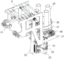
FIG. 1 is a schematic diagram of a ceramic membrane production system according to the present invention;
FIG. 2 is a schematic view of the cloth conveying mechanism and the blanking mechanism of FIG. 1;
FIG. 3 is a schematic structural view of a part of the cloth conveying mechanism in FIG. 2;
FIG. 4 is an enlarged view of a portion of FIG. 3 at A;
FIG. 5 is a schematic structural view of a portion of the blanking mechanism shown in FIG. 2;
FIG. 6 is a schematic view of a portion of the structure of FIG. 5;
FIG. 7 is a schematic view of a portion of the structure of FIG. 6;
FIG. 8 is a schematic view of the first heat-sealing mechanism of FIG. 5;
FIG. 9 is a schematic view of the second heat-sealing mechanism of FIG. 1;
FIG. 10 is a schematic view of a portion of the structure of FIG. 9;
FIG. 11 is a schematic view of the support structure of FIG. 9;
FIG. 12 is a schematic view of the guide cylinder of FIG. 5;
fig. 13 is a cross-sectional view of the structure of the lower hopper of fig. 1.
Detailed Description
The technical solution in the embodiments of the present invention will be clearly and completely described below with reference to the accompanying drawings in the embodiments of the present invention.
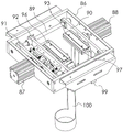
As shown in fig. 1 to 13, the ceramic film production system of the present invention includes a bagging device 1, the bagging device 1 includes a frame 2, a cloth conveying mechanism 3, a blanking mechanism 4, a first heat sealing mechanism 5, and a second heat sealing mechanism 6, and the frame 2 has a universal wheel 7 at a lower end thereof.
The frame 2 is provided with a first fixing plate 21, a second fixing plate 22 and a third fixing plate 23, the blanking mechanism 4 is arranged on the first fixing plate 21, the second fixing plate 22 is arranged at the lower end of the first fixing plate 21, the third fixing plate 23 is arranged at the lower end of the second fixing plate 22,
the cloth conveying mechanism 3 is installed on the frame 2, the cloth conveying mechanism 3 comprises a fourth fixing plate 8, the fourth fixing plate 8 is installed on the frame 2, and a third rotating rod 9, a fixing rod 10, a first guide rod 11, a second guide rod 12, a third guide rod 13, a fourth guide rod 14, a driving rod 15, a fifth guide rod 16 and a sixth guide rod 17 are arranged on the fourth fixing plate 8. The fixing rod 10 is provided with a connecting rod 18, the connecting rod 18 is provided with a third motor 19, the third motor 19 is provided with a pushing wheel 20, the lower end of the driving rod 15 between the third guide rod 13 and the fourth guide rod 14 is positioned, the first guide rod 11, the second guide rod 12, the third guide rod 13, the fourth guide rod 11 and the fifth guide rod 16 are positioned on the same horizontal plane, and the fifth guide rod 16 is positioned at the upper end of the sixth guide rod 17.
The first fixing plate 21 is provided with a fixing frame 24, the fixing frame 24 is provided with a guide cylinder 25, the guide cylinder 25 is composed of a conical cylinder 26 and a cylindrical cylinder 27, and the conical cylinder 26 is positioned at the upper end of the cylindrical cylinder 27. The conical cylinder 26 and the cylindrical cylinder 27 are provided with notches 28, the notches 28 on the conical cylinder 26 are provided with arc-shaped plates 29, and the lower end of the cylindrical cylinder 27 is provided with a stop rod 30. The holder 24 has an annular aperture 31. The bolt is installed in the annular hole 31, and the installation angle of the guide cylinder 25 can be adjusted through the annular hole 31, so that the blanking angle of the guide cylinder 25 is adjusted.
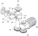
The two ends of the third rotating rod 9 are provided with a limiting piece 32, a supporting rod 33 and a supporting block 34, the supporting rod 33 is installed on the fourth fixing plate 8, the supporting block 34 is installed on the supporting rod 33, the supporting block 34 is provided with a roller 36, the two ends of the third rotating rod 9 are provided with limiting grooves 37, the supporting block 34 is provided with a groove 38, the roller 36 is placed in the limiting groove 37, the end of the third rotating rod 9 is placed in the groove 38, the supporting rod 33 at one end is provided with a screw 39, and the screw 39 is connected with the supporting block 34. The position of the supporting block 34 can be adjusted by pushing the screw 39, thereby facilitating the removal of the third rotating bar 9 from the supporting block 34.
The fourth fixing plate 8 is further provided with a second sliding rod 40, the second sliding rod 40 is provided with a second sliding block 41, the second sliding block 41 is provided with a vertical rod 42 and a screw rod 43, the vertical rod 42 and the screw rod 43 are provided with a fifth fixing plate 44, the fifth fixing plate 44 is provided with a fourth motor 45, the fourth motor 45 is connected with the driving rod 15 through a belt (not shown in the figure), and the lower end of the screw rod 43 is provided with an adjusting part 46. The lead screw 43 can be rotated by rotating the adjustment portion 46, thereby adjusting the height of the second slider 41, that is, the height of the fourth motor 45.
The cloth is transferred from the third rotating rod 9 by the driving of the third motor 19 and the fourth motor 45, and then is wound around the first guide rod 11, then is wound around the lower end of the second guide rod 12, then is wound around the upper end of the third guide rod 13, then is wound around the lower end of the driving rod 15, then is wound around the upper end of the fourth guide rod 14, then is wound around the upper end of the fifth guide rod 16, then is wound around the sixth guide rod 17, and then enters the guide cylinder 25, is guided by the arc plate 29 of the tapered cylinder 26, and then enters the notch 28 on the cylindrical cylinder 27 at the lower end.
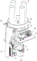
The first fixing plate 21 has a support rod 47, a first motor 48 and a support cylinder 49, the support rod 47 has a support plate 50, and the support plate 50 has a discharge hopper 51. The first motor 48 has a first gear 52 at a lower end thereof, the support cylinder 49 has a first rotating rod 53 therein, the first rotating rod 53 has a second gear 54 at a lower end thereof, and the second gear 54 is engaged with the first gear 52.
The supporting cylinder 49 is provided with a positioning seat 55, the positioning seat 55 is provided with a first rotating plate 56, the first rotating plate 56 is provided with a second rotating plate 57, the first rotating rod 53 is provided with a rotating member 58, the rotating member 58 is provided with a discharging pipe 59, the lower end of the discharging pipe 59 extends to a position between the rotating member 58 and the second rotating plate 57, the first rotating plate 56 and the second rotating plate 57 are provided with a discharging hole 60 in an upward direction, and the discharging pipe 59 is arranged at the lower end of the discharging hopper 51. The first and second rotating plates 56 and 57 do not rotate, but the rotating member 58 is rotated by the first motor 48.
The lower hopper 51 has a guide 61 in the middle, and the lower end of the guide 61 has an arc-shaped guide portion 62.
The supporting cylinder 49 is provided with a fixed seat 63, two sides of the fixed seat 63 are provided with clamping plates 64, the clamping plates 64 are provided with clamping grooves 65, two sides of the positioning seat 63 are provided with clamping columns 66, the clamping columns 66 are arranged in the clamping grooves 65, the fixed seat 63 is hinged with an adjusting rod 67, the clamping plates 64 are provided with adjusting blocks 68, the adjusting rod 67 is arranged in the adjusting blocks 68, and the adjusting rod 67 is further provided with a hand wheel 69.
The staff places the ceramic membrane in hopper 51 down, leads through arc guide part 62, then makes the ceramic membrane enter into the unloading pipe 59 of lower extreme, and the rotation of rethread first motor 48 removes for the unloading pipe 59 that has the ceramic membrane removes the upper end in unloading hole 60, then falls down from unloading hole 60, and the rethread leads the guide cylinder 25 of good cloth and leads and fall down, parcel ceramic membrane.
The first heat sealing mechanism 5 is mounted on the third fixing plate 23, the first heat sealing mechanism 5 has a fixing block 71 therein, the fixing block 71 is mounted on the third fixing plate 72, the fixing block 71 has a first cylinder 73 thereon, the middle of the fixing block 71 has a first slide bar 74, the first slide bar 74 has a first push plate 75 thereon, the first push plate 75 is connected with the first cylinder 73, the first push plate 75 has a first heat sealing block 76 thereon, and the fixing block 76 has a second heat sealing block 77 thereon. The first cylinder 73 pushes the first push plate 75 so that the first heat seal block 76 on the first push plate 75 moves toward the second heat seal block 77.
The second fixed plate 22 is provided with a second motor 70, the second motor 70 is provided with a third gear 78 and a first guide disc 79, the second fixed plate 22 is provided with a sliding groove 80, the sliding groove 80 is provided with a first sliding block 81, the first sliding block 81 is provided with a fourth gear 82 and a second guide disc 83, and the third gear 78 is meshed with the fourth gear 82. The first slider 81 has a second rotating rod 84, and the second rotating rod 84 has a first spring 85.
The second motor 70 is driven to press both ends of the cloth in advance so that the first heat-sealing mechanism 5 at the lower end heat-seals the cloth.
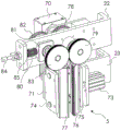
The second heat sealing mechanism 6 comprises a fixed frame 86, a second air cylinder 87 and a third air cylinder 88, wherein the second air cylinder 87 and the third air cylinder 88 are installed on the fixed frame 86 and are oppositely installed, a third sliding rod 89 is arranged in the middle of the fixed frame 86, a second push plate 90, a third push plate 91 and a fourth push plate 92 are arranged on the third sliding rod 89, the second air cylinder 87 is connected with the second push plate 90, a third heat sealing block 93 is arranged on the second push plate 90, and the third push plate 91 is installed on the third air cylinder 88. The third push plate 91 is provided with a convex plate 94, both ends of the convex plate 94 are provided with fourth sliding rods 95, the fourth sliding rods 95 are installed in the middle of the fourth push plate 92, the fourth push plate 92 is provided with a fourth heat sealing block 96, a knife groove 97 is arranged between the third heat sealing block 93 and the fourth heat sealing block 96, the fourth sliding rods 95 are provided with a cutter 98, and the cutter 98 is arranged in the knife groove 97 in the fourth heat sealing block 96.
The second push plate 90 has a rod 99 at a lower end thereof, a support member 100 on the rod 99, a fixing portion 101 and a placing portion 102 on the support member 100, a mounting plate 103 on the fixing portion 101, a second spring 104 on the mounting plate 103, and a guide plate 105 at the other end of the second spring 104. The guide plate 105 is for guiding the ceramic membrane.
The second heat sealing mechanism 6 performs heat sealing on the lower end of the cloth, and during heat sealing, the second air cylinder 87 pushes the second push plate 90 to move first, so that the third heat sealing block 93 moves to move towards the fourth heat sealing block 96, then the third air cylinder 88 moves to push the convex plate 94, so that the cutter 98 on the fourth sliding rod 95 on the convex plate 94 enters the cutter groove 97 of the third heat sealing block 93, and the cloth is cut off. And then dropped onto the placing portion 102 of the support 100, and the second air cylinder 87 and the third air cylinder 88 at the upper end are moved again, heat-sealed and cut.
The above description is only for the purpose of illustrating the preferred embodiments of the present invention and is not to be construed as limiting the invention, and any modifications, equivalents and improvements made within the spirit and principles of the present invention are intended to be included within the scope of the present invention.
Claims (10)
1. A ceramic membrane production system comprises a bagging device and is characterized in that the bagging device comprises a rack, a cloth conveying mechanism, a blanking mechanism, a first heat-sealing mechanism and a second heat-sealing mechanism, universal wheels are arranged at the lower end of the rack, the cloth conveying mechanism is arranged on the rack, a first fixing plate, a second fixing plate and a third fixing plate are arranged on the rack, the blanking mechanism is arranged on the first fixing plate, the second fixing plate is arranged at the lower end of the first fixing plate, the third fixing plate is arranged at the lower end of the second fixing plate, a supporting rod, a first motor and a supporting cylinder are arranged on the first fixing plate, a supporting plate is arranged on the supporting rod, a blanking hopper is arranged on the supporting plate, a first gear is arranged at the lower end of the first motor, a first rotating rod is arranged in the supporting cylinder, a second gear is arranged at the lower end of the first rotating rod, the second gear is meshed with the first gear, the supporting cylinder is provided with a positioning seat, the positioning seat is provided with a first rotating plate, the first rotating plate is provided with a second rotating plate, the first rotating rod is provided with a rotating piece, the rotating piece is provided with a discharging pipe, the lower end of the discharging pipe extends to a position between the rotating piece and the second rotating plate, the first rotating plate and the second rotating plate are provided with discharging holes in an upward mode, the discharging pipe is arranged at the lower end of a discharging hopper,
the first heat sealing mechanism is arranged on a third fixing plate, a fixing block is arranged in the first heat sealing mechanism, the fixing block is arranged on the third fixing plate, a first air cylinder is arranged on the fixing block, a first sliding rod is arranged in the middle of the fixing block, a first push plate is arranged on the first sliding rod, the first push plate is connected with the first air cylinder, a first heat sealing block is arranged on the first push plate, and a second heat sealing block is arranged on the fixing block;
the cloth conveying mechanism comprises a fourth fixed plate which is arranged on the frame, the fourth fixed plate is provided with a third rotating rod, a fixed rod, a first guide rod, a second guide rod, a third guide rod, a fourth guide rod, a driving rod, a fifth guide rod and a sixth guide rod, the fixed rod is provided with a connecting rod, the connecting rod is provided with a third motor, the third motor is provided with a pushing wheel, the driving rod is arranged at the lower end between the third guide rod and the fourth guide rod, the first guide rod, the second guide rod, the third guide rod, the fourth guide rod and the fifth guide rod are positioned on the same horizontal plane, the fifth guide rod is positioned at the upper end of the sixth guide rod, the first fixing plate is provided with a fixing frame, the fixed frame is provided with a guide cylinder, the guide cylinder consists of a conical cylinder and a cylindrical cylinder, and the conical cylinder is positioned at the upper end of the cylindrical cylinder;
the second heat-sealing mechanism comprises a fixed frame, a second cylinder and a third cylinder, the second cylinder and the third cylinder are installed on the fixed frame and are installed oppositely, a third sliding rod is arranged in the middle of the fixed frame, a second push plate, a third push plate and a fourth push plate are arranged on the third sliding rod, the second cylinder is connected with the second push plate, a third heat-sealing block is arranged on the second push plate, the third push plate is installed on the third cylinder, a convex plate is arranged on the third push plate, fourth sliding rods are arranged at two ends of the convex plate, the fourth sliding rod is installed in the middle of the fourth push plate, a fourth heat-sealing block is arranged on the fourth push plate, a cutter groove is arranged in the middle of the third heat-sealing block and the fourth heat-sealing block, a cutter is arranged on the fourth sliding rod, and the cutter is arranged in the cutter groove in the fourth heat-sealing block.
2. A ceramic membrane production system according to claim 1, wherein the lower hopper has a guide member in the middle, and the guide member has an arc-shaped guide portion at its lower end.
3. The ceramic membrane production system according to claim 1, wherein the support cylinder has a fixing base, the fixing base has two clamping plates on two sides thereof, the clamping plates have clamping grooves, the positioning base has two clamping posts on two sides thereof, the clamping posts are disposed in the clamping grooves, the fixing base is hinged with an adjusting rod, the clamping plates have adjusting blocks thereon, the adjusting rod is mounted in the adjusting blocks, and the adjusting rod further has a hand wheel thereon.
4. A ceramic membrane production system according to claim 1, wherein the second fixing plate has a second motor thereon, the second motor has a third gear and a first guiding disc thereon, the second fixing plate has a sliding slot therein, the sliding slot has a first slide block therein, the first slide block has a fourth gear and a second guiding disc thereon, and the third gear is engaged with the fourth gear.
5. A ceramic membrane production system according to claim 4, wherein the first slider block has a second rotating rod thereon, and the second rotating rod has a first spring thereon.
6. The ceramic membrane production system according to claim 1, wherein the third rotating rod has a limiting member, a supporting rod and a supporting block at two ends, the supporting rod is mounted on the fourth fixing plate, the supporting block is mounted on the supporting rod, the supporting block has a roller thereon, the third rotating rod has a limiting groove at two ends, the supporting block has a groove thereon, the roller is disposed in the limiting groove, the end of the third rotating rod is disposed in the groove, the supporting rod at one end has a screw thereon, and the screw is connected with the supporting block.
7. The ceramic membrane production system according to claim 1, wherein the fourth fixing plate further comprises a second slide bar, the second slide bar comprises a second slide block, the second slide block comprises a vertical bar and a screw rod, the vertical bar and the screw rod comprise a fifth fixing plate, the fifth fixing plate comprises a fourth motor, the fourth motor is connected with the driving bar through a belt, and the lower end of the screw rod comprises an adjusting portion.
8. The ceramic membrane production system of claim 1, wherein the conical cylinder and the cylindrical cylinder are provided with notches, the notches of the conical cylinder are provided with arc-shaped plates, and the lower end of the cylindrical cylinder is provided with a stop bar.
9. A ceramic membrane production system according to claim 1, wherein the fixture has an annular aperture therein.
10. A ceramic membrane production system according to claim 1, wherein the second pushing plate has a supporting rod at a lower end thereof, the supporting rod has a supporting member thereon, the supporting member has a fixing portion and a placing portion thereon, the fixing portion has a mounting plate thereon, the mounting plate has a second spring thereon, and the other end of the second spring has a guide plate.
Priority Applications (1)
| Application Number | Priority Date | Filing Date | Title |
|---|---|---|---|
| CN202011258217.4A CN112520130B (en) | 2020-11-12 | 2020-11-12 | Ceramic membrane production system |
Applications Claiming Priority (1)
| Application Number | Priority Date | Filing Date | Title |
|---|---|---|---|
| CN202011258217.4A CN112520130B (en) | 2020-11-12 | 2020-11-12 | Ceramic membrane production system |
Publications (2)
| Publication Number | Publication Date |
|---|---|
| CN112520130A true CN112520130A (en) | 2021-03-19 |
| CN112520130B CN112520130B (en) | 2022-04-26 |
Family
ID=74981580
Family Applications (1)
| Application Number | Title | Priority Date | Filing Date |
|---|---|---|---|
| CN202011258217.4A Active CN112520130B (en) | 2020-11-12 | 2020-11-12 | Ceramic membrane production system |
Country Status (1)
| Country | Link |
|---|---|
| CN (1) | CN112520130B (en) |
Citations (9)
| Publication number | Priority date | Publication date | Assignee | Title |
|---|---|---|---|---|
| GB1471361A (en) * | 1973-04-04 | 1977-04-27 | Dow Chemical Co | Method and apparatus for forming filling and sealing bags |
| CN2693656Y (en) * | 2003-09-30 | 2005-04-20 | 中山丰源塑料机械制品有限公司 | Rod-like full automatic packing machine |
| CN103832609A (en) * | 2013-12-31 | 2014-06-04 | 红塔烟草(集团)有限责任公司 | Heat-seal packaging device |
| CN107200150A (en) * | 2016-03-16 | 2017-09-26 | 王桂华 | Prepared slices of Chinese crude drugs automatic weighing and packing machine |
| CN207242186U (en) * | 2017-06-08 | 2018-04-17 | 武汉宏远高新技术工程有限责任公司 | A kind of Small bag packaging machine |
| CN209023233U (en) * | 2018-09-30 | 2019-06-25 | 天津中益包装科技股份有限公司 | A kind of upright packing machine with vacuum film drawing device |
| CN212074571U (en) * | 2018-10-19 | 2020-12-04 | 天津中益包装科技股份有限公司 | Vertical automatic packaging machine |
| CN112278444A (en) * | 2020-11-27 | 2021-01-29 | 瑞昌市渝瑞实业有限公司 | Continuous packaging equipment of chinese yam piece |
| CN113291515A (en) * | 2021-06-17 | 2021-08-24 | 杭州荣祥包装科技有限公司 | Vertical automatic bag making and packaging machine |
-
2020
- 2020-11-12 CN CN202011258217.4A patent/CN112520130B/en active Active
Patent Citations (9)
| Publication number | Priority date | Publication date | Assignee | Title |
|---|---|---|---|---|
| GB1471361A (en) * | 1973-04-04 | 1977-04-27 | Dow Chemical Co | Method and apparatus for forming filling and sealing bags |
| CN2693656Y (en) * | 2003-09-30 | 2005-04-20 | 中山丰源塑料机械制品有限公司 | Rod-like full automatic packing machine |
| CN103832609A (en) * | 2013-12-31 | 2014-06-04 | 红塔烟草(集团)有限责任公司 | Heat-seal packaging device |
| CN107200150A (en) * | 2016-03-16 | 2017-09-26 | 王桂华 | Prepared slices of Chinese crude drugs automatic weighing and packing machine |
| CN207242186U (en) * | 2017-06-08 | 2018-04-17 | 武汉宏远高新技术工程有限责任公司 | A kind of Small bag packaging machine |
| CN209023233U (en) * | 2018-09-30 | 2019-06-25 | 天津中益包装科技股份有限公司 | A kind of upright packing machine with vacuum film drawing device |
| CN212074571U (en) * | 2018-10-19 | 2020-12-04 | 天津中益包装科技股份有限公司 | Vertical automatic packaging machine |
| CN112278444A (en) * | 2020-11-27 | 2021-01-29 | 瑞昌市渝瑞实业有限公司 | Continuous packaging equipment of chinese yam piece |
| CN113291515A (en) * | 2021-06-17 | 2021-08-24 | 杭州荣祥包装科技有限公司 | Vertical automatic bag making and packaging machine |
Also Published As
| Publication number | Publication date |
|---|---|
| CN112520130B (en) | 2022-04-26 |
Similar Documents
| Publication | Publication Date | Title |
|---|---|---|
| JPH084722B2 (en) | Membrane separation device | |
| US20160016122A1 (en) | Method for operating reverse osmosis membrane device, and reverse osmosis membrane device | |
| CN112520130B (en) | Ceramic membrane production system | |
| GB1429543A (en) | Supporting member for reverse osmosis membranes a process for manufacturing the member and a reverse osmotic filtration apparat | |
| CN111113982B (en) | Residue separation system based on cyclic treatment in ceramic membrane separation process | |
| CN111495028B (en) | Biological fermentation membrane separation and purification equipment | |
| CN220071272U (en) | Inorganic ceramic membrane filtration equipment | |
| CN211274247U (en) | MBR hollow flat plate filter ceramic membrane | |
| CN210905696U (en) | Ultrafiltration device convenient to transport | |
| CN212504132U (en) | Dull and stereotyped ceramic membrane filtration system | |
| Bilstad | Membrane operations | |
| CN208746556U (en) | Sewage treatment diaphragm unit support device | |
| CN218476936U (en) | Ceramic membrane processing is with cuting device | |
| CN114053878A (en) | Method and equipment for treating melamine wastewater by using ultrafiltration membrane | |
| CN116459674B (en) | Preparation method and preparation device of pollution-resistant composite reverse osmosis membrane component | |
| CN212549048U (en) | Ceramic membrane pipe dredging and pressing device | |
| CN109569811B (en) | Reducing mechanism of ceramic membrane raw materials | |
| CN220245677U (en) | Portable reverse osmosis filter device | |
| CN219469185U (en) | Shearing device for filtering film | |
| CN216282768U (en) | Firing equipment for ceramic membrane element | |
| CN215822796U (en) | Ceramic membrane pipeline material recovery structure | |
| CN220745495U (en) | Off-line film supplementing device for large seawater desalination ultrafiltration film | |
| CN216498617U (en) | Multichannel column ceramic membrane | |
| CN218145972U (en) | Domestic waste leachate DTRO membrane system treatment section dish tubular membrane column | |
| CN216638408U (en) | Conveying mechanism of RO membrane folder |
Legal Events
| Date | Code | Title | Description |
|---|---|---|---|
| PB01 | Publication | ||
| PB01 | Publication | ||
| SE01 | Entry into force of request for substantive examination | ||
| SE01 | Entry into force of request for substantive examination | ||
| GR01 | Patent grant | ||
| GR01 | Patent grant |