CN112486285A - Intelligent thermal management system and thermal management method for computer - Google Patents
Intelligent thermal management system and thermal management method for computer Download PDFInfo
- Publication number
- CN112486285A CN112486285A CN202011376683.2A CN202011376683A CN112486285A CN 112486285 A CN112486285 A CN 112486285A CN 202011376683 A CN202011376683 A CN 202011376683A CN 112486285 A CN112486285 A CN 112486285A
- Authority
- CN
- China
- Prior art keywords
- thermal management
- fan
- temperature value
- strategy
- pump
- Prior art date
- Legal status (The legal status is an assumption and is not a legal conclusion. Google has not performed a legal analysis and makes no representation as to the accuracy of the status listed.)
- Pending
Links
- 238000007726 management method Methods 0.000 title abstract description 41
- 230000017525 heat dissipation Effects 0.000 claims abstract description 40
- 239000007788 liquid Substances 0.000 claims abstract description 21
- 239000012530 fluid Substances 0.000 claims abstract description 19
- 239000000110 cooling liquid Substances 0.000 claims abstract description 12
- 230000008859 change Effects 0.000 claims description 16
- 238000000034 method Methods 0.000 claims description 13
- 238000001816 cooling Methods 0.000 description 28
- 238000005516 engineering process Methods 0.000 description 17
- 238000005265 energy consumption Methods 0.000 description 6
- 230000003044 adaptive effect Effects 0.000 description 5
- 238000012423 maintenance Methods 0.000 description 5
- 239000002699 waste material Substances 0.000 description 4
- 230000000875 corresponding effect Effects 0.000 description 3
- 238000012546 transfer Methods 0.000 description 3
- 230000008901 benefit Effects 0.000 description 2
- 230000001276 controlling effect Effects 0.000 description 2
- 238000013461 design Methods 0.000 description 2
- 238000010438 heat treatment Methods 0.000 description 2
- 230000008569 process Effects 0.000 description 2
- 230000002035 prolonged effect Effects 0.000 description 2
- 230000008646 thermal stress Effects 0.000 description 2
- 230000009471 action Effects 0.000 description 1
- 230000009286 beneficial effect Effects 0.000 description 1
- 238000009835 boiling Methods 0.000 description 1
- 238000011217 control strategy Methods 0.000 description 1
- 238000011161 development Methods 0.000 description 1
- 238000010586 diagram Methods 0.000 description 1
- 230000007613 environmental effect Effects 0.000 description 1
- 230000004907 flux Effects 0.000 description 1
- 230000010354 integration Effects 0.000 description 1
- 238000004377 microelectronic Methods 0.000 description 1
- 239000007921 spray Substances 0.000 description 1
Images


Classifications
-
- G—PHYSICS
- G06—COMPUTING; CALCULATING OR COUNTING
- G06F—ELECTRIC DIGITAL DATA PROCESSING
- G06F1/00—Details not covered by groups G06F3/00 - G06F13/00 and G06F21/00
- G06F1/16—Constructional details or arrangements
- G06F1/18—Packaging or power distribution
- G06F1/183—Internal mounting support structures, e.g. for printed circuit boards, internal connecting means
-
- G—PHYSICS
- G06—COMPUTING; CALCULATING OR COUNTING
- G06F—ELECTRIC DIGITAL DATA PROCESSING
- G06F1/00—Details not covered by groups G06F3/00 - G06F13/00 and G06F21/00
- G06F1/16—Constructional details or arrangements
- G06F1/20—Cooling means
-
- G—PHYSICS
- G06—COMPUTING; CALCULATING OR COUNTING
- G06F—ELECTRIC DIGITAL DATA PROCESSING
- G06F1/00—Details not covered by groups G06F3/00 - G06F13/00 and G06F21/00
- G06F1/26—Power supply means, e.g. regulation thereof
- G06F1/32—Means for saving power
- G06F1/3203—Power management, i.e. event-based initiation of a power-saving mode
- G06F1/3206—Monitoring of events, devices or parameters that trigger a change in power modality
-
- G—PHYSICS
- G06—COMPUTING; CALCULATING OR COUNTING
- G06F—ELECTRIC DIGITAL DATA PROCESSING
- G06F1/00—Details not covered by groups G06F3/00 - G06F13/00 and G06F21/00
- G06F1/26—Power supply means, e.g. regulation thereof
- G06F1/32—Means for saving power
- G06F1/3203—Power management, i.e. event-based initiation of a power-saving mode
- G06F1/3234—Power saving characterised by the action undertaken
- G06F1/3287—Power saving characterised by the action undertaken by switching off individual functional units in the computer system
-
- G—PHYSICS
- G06—COMPUTING; CALCULATING OR COUNTING
- G06F—ELECTRIC DIGITAL DATA PROCESSING
- G06F11/00—Error detection; Error correction; Monitoring
- G06F11/30—Monitoring
- G06F11/3058—Monitoring arrangements for monitoring environmental properties or parameters of the computing system or of the computing system component, e.g. monitoring of power, currents, temperature, humidity, position, vibrations
-
- G—PHYSICS
- G06—COMPUTING; CALCULATING OR COUNTING
- G06F—ELECTRIC DIGITAL DATA PROCESSING
- G06F2200/00—Indexing scheme relating to G06F1/04 - G06F1/32
- G06F2200/20—Indexing scheme relating to G06F1/20
- G06F2200/201—Cooling arrangements using cooling fluid
Abstract
The application provides a computer intelligent thermal management system and a thermal management method, the computer intelligent thermal management system comprises an electronic module (1), a case (2), a fluid pipeline (3), a radiator (4), a fan (5), a pump (6), a liquid storage device (7) and a control module (8), wherein: the case (2) is of a box body structure, the side wall of the case (2) is provided with a vent hole (21), the side wall of the case is provided with a channel (22) for fluid to flow, and cooling liquid for heat dissipation is arranged in the channel (22); a plurality of electronic modules (1) are arranged in the case (2), a plurality of electronic elements (11) are arranged in the electronic modules (1), heat dissipation fins (12) are arranged outside the electronic modules (1), and temperature sensors are arranged on the electronic elements (11) and connected with the control module (8); the radiator (4) is provided with a radiator passage (41) and fins (42) through which a fluid can flow.
Description
Technical Field
The application relates to the heat dissipation technology of electronic equipment, in particular to an intelligent heat management system and a heat management method for a computer
Background
Owing to the rapid development of microelectronic technology, the performance of integrated circuits is continuously improved, and electronic devices represented by computers are developing toward miniaturization, integration and high density, which makes the heat flux density of electronic chips higher and higher. However, the failure rate of the electronic device is closely related to the temperature, and the reliability of the chip is reduced due to the increase of the temperature, so that the heat management technology for controlling the temperature of the chip is increasingly emphasized. The traditional electronic equipment heat management technology comprises natural heat dissipation, air cooling, liquid cooling technology and the like, wherein the natural heat dissipation is to dissipate the heat of the electronic equipment into the air by means of natural convection (the convection heat transfer coefficient is about 5-25W/m < 2 > 2K); in the air cooling technology, a fan is used for driving air to flow inside or outside the electronic equipment, so that the convection heat transfer coefficient (approximately 20-100W/m < 2 > 2K) is improved, and the heat dissipation capability is improved; the liquid cooling technology adopts direct contact between cooling liquid and electronic equipment to transfer heat into the cooling liquid, and compared with the technology adopting air as a medium, the liquid has the advantage that the heat convection coefficient (approximately 50-15000W/m < 2 > 2K) is greatly improved, so that the heat dissipation capacity is strongest.
In addition, various new heat management technologies with stronger heat dissipation capability, such as spray cooling, jet cooling, boiling heat exchange, etc., are continuously developed, and these new heat dissipation technologies can be applied under certain specific conditions, however, since the complexity of these new heat dissipation technologies is greatly increased, the most widely applied electronic devices are still natural heat dissipation, air cooling and liquid cooling technologies. The natural heat dissipation method has the lowest heat dissipation capability, but has the advantages of simple structure, low cost and high reliability. The heat dissipation capacity of the air cooling technology and the liquid cooling technology is improved, but the air cooling technology needs a fan, and a liquid cooling system comprises parts such as a fluid pipeline, cooling liquid, a pump, a valve and the like, so that the weight, the energy consumption and the volume are increased, the reliability is reduced, and the cost is improved.
At present, the design of a thermal management system generally takes the maximum thermal power consumption and the highest ambient temperature of a computer as design conditions, and selects a heat dissipation technology meeting the requirement of heat dissipation capacity. However, when different work tasks are performed, the heat productivity of the computer is greatly changed, the environment temperature of the computer is changed along with the change of external conditions, and the requirement of the computer for the heat dissipation capacity is also changed. For electronic equipment with high peak heat dissipation requirements and low average heat dissipation requirements, the liquid cooling system is adopted for heat dissipation, which brings great waste of heat dissipation resources.
In addition, since the computer electronic chip does not include moving parts, the chip often has a long service life, and the service life of rotating mechanical parts such as fans, pumps and the like in the air cooling system and the liquid cooling system is usually greatly shorter than that of the chip. In the whole life cycle of electronic equipment such as a computer, heat management system components such as a fan and a pump need to be replaced for many times, which increases the maintenance difficulty and cost.
In summary, the existing computer thermal management system adopting the liquid cooling technology has the disadvantages of large waste of cooling resources, short service life and high maintenance difficulty.
Disclosure of Invention
The invention discloses an intelligent heat management system and method for a computer, which are used for heat dissipation of the computer. The intelligent heat management system and the intelligent heat management method for the computer have three heat dissipation modes of natural heat dissipation, air cooling and liquid cooling, and can automatically select the heat dissipation mode adaptive to the state of the computer from the liquid cooling, air cooling and natural heat dissipation modes according to the heat productivity and the environmental temperature change of the computer, thereby reducing the energy consumption of the heat management system in the whole life cycle, prolonging the service life of the heat management system, reducing the maintenance cost of the heat management system and improving the reliability of the computer.
In a first aspect, the present application provides a computer intelligent thermal management system, which includes an electronic module (1), a chassis (2), a fluid pipeline (3), a heat sink (4), a fan (5), a pump (6), a liquid storage device (7), and a control module (8), wherein:
the case (2) is of a box body structure, the side wall of the case (2) is provided with a vent hole (21), the side wall of the case is provided with a channel (22) for fluid to flow, and cooling liquid for heat dissipation is arranged in the channel (22); a plurality of electronic modules (1) are arranged in the case (2), a plurality of electronic elements (11) are arranged in the electronic modules (1), heat dissipation fins (12) are arranged outside the electronic modules (1), and temperature sensors are arranged on the electronic elements (11) and connected with the control module (8); the radiator (4) is provided with a radiator channel (41) and fins (42) for fluid flow, gaps for air flow are formed among the fins (42), and cooling liquid is filled in the radiator channel (41); the channel (22) is connected with the radiator channel (41) through a fluid pipeline (3); the radiator (4) is arranged between the case (2) and the fan (5); the fan (5) is connected with the control module (8) through a pump (6) and a liquid storage device (7) in sequence; the control module (8) is arranged on the case (2) and used for controlling the opening, closing and running speed of the pump (6) and the fan (5).
In particular, the coverage area of the fan (5) comprises all the electronic modules (1).
In a second aspect, the present application provides a thermal management method applied to the computer intelligent thermal management system of claim 1, the method comprising:
the temperature sensor collects the temperature value of the electronic element (11) and sends the temperature value to the control module (8);
the control module (8) determines a corresponding thermal management strategy according to the temperature value and the temperature change rate;
the control module (8) controls the on, off and operating speeds of the pump (6) and fan (5) according to the determined thermal management strategy.
Specifically, the determining, by the control module (8), the corresponding thermal management policy according to the temperature value and the temperature change rate specifically includes:
when the temperature value is less than T1, determining that the thermal management strategy is a first power consumption strategy;
when the temperature value is greater than T1, the temperature value is less than T2, and the temperature change rate is less than 0, determining that the thermal management strategy is a first power consumption strategy;
when the temperature value is greater than T1, the temperature value is less than T2, and the temperature change rate is greater than 0, determining that the thermal management strategy is a second power consumption strategy;
when the temperature value is greater than T2, the temperature value is less than T3, and the temperature change rate is less than 0, determining that the thermal management strategy is a second power consumption strategy;
when the temperature value is greater than T2, the temperature value is less than T3, and the temperature change rate is greater than 0, determining that the thermal management strategy is a third power consumption strategy;
and when the temperature value is greater than T3, determining the thermal management strategy as a fourth power consumption strategy.
Specifically, the first power consumption strategy is to turn off the pump (6) and the fan (5).
Specifically, the second power consumption strategy is to turn on the fan (5) and turn off the pump (6).
Specifically, the third power consumption strategy is to turn on the fan (5), turn on the pump (6), and maintain the pump (6) in a low rotation state.
Specifically, the fourth power consumption strategy is to turn on the fan (5), turn on the pump (6), and maintain the pump (6) in a high rotation state.
The invention has the beneficial effects that:
according to the real-time temperature value of the electronic component, a heat dissipation mode adaptive to the state of the computer is automatically selected from liquid cooling, air cooling and natural heat dissipation modes, so that the heat management system is prevented from continuously operating in a high-energy-consumption state, the energy consumption of the operation of the heat management system is reduced, and the waste of cooling resources is avoided.
When the heating value of the electronic component is small, the continuous operation time of a pump, a fan and the like is reduced by automatically selecting a heat dissipation mode which is adaptive to the state of a computer, so that the service life of the heat management system is prolonged, and the maintenance difficulty and cost are reduced.
The temperature of the electronic component can be accurately controlled, thermal stress caused by severe fluctuation of the temperature of the electronic component is avoided, and the reliability of the electronic component is improved.
Drawings
FIG. 1 is a schematic diagram of the principles of the present invention;
FIG. 2 is a schematic view of a fin of an electronic module of the present invention;
FIG. 3 is a schematic view of the opening of the upper and lower sidewalls of the case;
FIG. 4 is a schematic view of a heat sink;
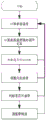
FIG. 5 is a schematic view of the working process of the present invention;
the system comprises an electronic module 1, a chassis 2, a fluid pipeline 3, a radiator 4, a fan 5, a pump 6, a liquid storage device 7, a control module 8, electronic components 11, radiating fins 12, channels 22, vent holes 21, radiator channels 41 and fins 42.
Detailed Description
The computer system comprises an electronic module (1), a case (2), a fluid pipeline (3), a radiator (4), a fan (5), a pump (6), a liquid storage device (7), a control module (8) and the like. The electronic module comprises an electronic element (11) inside, a radiating fin (12) outside, and the temperature of the electronic element is measured by a temperature sensor on the element and then output to the control module. The upper and lower side walls of the case are provided with vent holes (21), and a channel (22) for fluid flow is arranged in the case. The fluid pipeline is internally provided with cooling liquid for heat dissipation. A radiator channel (41) and fins (42) for fluid flow are arranged in the radiator, gaps for air flow are formed among the fins, a fluid circulation channel is formed by a flow channel in the radiator, a fluid pipeline, a flow channel in the case, a liquid storage device and a pump, and cooling liquid is arranged in the channel. The rotation speed of the fan and the pump can be continuously adjusted. The control module may control the on, off, and speed of operation of the pump and fan.
When the computer runs, the temperature of the electronic components rises due to heat generated by running after the computer is powered on. The temperature of the electronic components can be measured by temperature sensors integrated in the electronic components or by sensors attached to the outside of the components. After the temperature sensor measures the temperature of the electronic components, the temperature signal is transmitted to the control module through the circuit, and after the control module obtains the temperature of each electronic component, the operation and the output are carried out according to the flow shown in fig. 5, and the fan and the pump are controlled to execute corresponding actions. The control strategy is as follows:
when the sensors on the electronic components monitor that the highest temperature of all the electronic components is low, the computer has low requirement on heat dissipation, and the control module closes the pump and the fan at the moment. Because the upper side wall and the lower side wall of the case are both provided with the vent holes, and gaps for air to flow are formed among the fins of the radiator, the heat of the electronic module can be naturally convected and dissipated into the air through the fins outside the electronic module, the computer is in a natural heat dissipation state, and the heat management system does not consume energy at the moment.
When the sensor monitors that the highest temperature of all electronic components rises to a certain value, the control module starts the fan, the fan is adjusted to a proper rotating speed according to the temperature change of the electronic components, pressure difference is formed on two sides of the fan, external air enters the interior of the case from the lower part and the periphery of the case, passes through the surface of the electronic module and finally flows out of the fan. At the moment, the computer is in an air cooling state, the heat dissipation capacity is improved, and therefore the temperature of the electronic component is controlled within a certain range.
When the sensors monitor that the highest temperature of all the electronic components is further increased, the control module modulates the rotating speed of the fan to be the highest, starts the pump and adjusts the pump to be the proper rotating speed according to the temperature change of the electronic components. Under the drive of the pump, cooling liquid circularly flows in the pipeline, heat in the electronic module is transferred to the case and is transferred to the radiator through the cooling liquid, and under the action of the fan, the heat of the radiator is dissipated to the air through convection. At the same time, the fan drives the air over the surface of the electronic module, and a portion of the heat of the electronic module is dissipated directly into the air by convection. The radiator enlarges the radiating area, and the radiating capacity is highest at the moment, so that the temperature of the electronic component is controlled in a certain range.
Through the process, the heat management system automatically selects the heat dissipation mode adaptive to the computer state from the liquid cooling mode, the air cooling mode and the natural heat dissipation mode according to the real-time temperature value of the electronic component, so that the heat management system is prevented from continuously operating in a high energy consumption state, the energy consumption of the operation of the heat management system is reduced, and the waste of cooling resources is avoided. When the heating value of the electronic component is small, the continuous operation time of a pump, a fan and the like is reduced by automatically selecting a heat dissipation mode which is adaptive to the state of a computer, so that the service life of the heat management system is prolonged, and the maintenance difficulty and cost are reduced. The temperature of the electronic component can be accurately controlled, thermal stress caused by severe fluctuation of the temperature of the electronic component is avoided, and the reliability of the electronic component is improved.
Claims (8)
1. The computer intelligent thermal management system is characterized by comprising an electronic module (1), a case (2), a fluid pipeline (3), a radiator (4), a fan (5), a pump (6), a liquid storage device (7) and a control module (8), wherein:
the case (2) is of a box body structure, the side wall of the case (2) is provided with a vent hole (21), the side wall of the case is provided with a channel (22) for fluid to flow, and cooling liquid for heat dissipation is arranged in the channel (22); a plurality of electronic modules (1) are arranged in the case (2), a plurality of electronic elements (11) are arranged in the electronic modules (1), heat dissipation fins (12) are arranged outside the electronic modules (1), and temperature sensors are arranged on the electronic elements (11) and connected with the control module (8); the radiator (4) is provided with a radiator channel (41) and fins (42) for fluid flow, gaps for air flow are formed among the fins (42), and cooling liquid is filled in the radiator channel (41); the channel (22) is connected with the radiator channel (41) through a fluid pipeline (3); the radiator (4) is arranged between the case (2) and the fan (5); the fan (5) is connected with the control module (8) through a pump (6) and a liquid storage device (7) in sequence; the control module (8) is arranged on the case (2) and used for controlling the opening, closing and running speed of the pump (6) and the fan (5).
2. Computer intelligent thermal management system according to claim 1, characterized in that the coverage of the fan (5) comprises all electronic modules (1).
3. A method for thermal management, wherein the method is applied to the computer intelligent thermal management system of claim 1, and the method comprises:
the temperature sensor collects the temperature value of the electronic element (11) and sends the temperature value to the control module (8);
the control module (8) determines a corresponding thermal management strategy according to the temperature value and the temperature change rate;
the control module (8) controls the on, off and operating speeds of the pump (6) and fan (5) according to the determined thermal management strategy.
4. The method according to claim 3, wherein the control module (8) determines the corresponding thermal management strategy according to the temperature value and the temperature change rate, and specifically comprises:
when the temperature value is less than T1, determining that the thermal management strategy is a first power consumption strategy;
when the temperature value is greater than T1, the temperature value is less than T2, and the temperature change rate is less than 0, determining that the thermal management strategy is a first power consumption strategy;
when the temperature value is greater than T1, the temperature value is less than T2, and the temperature change rate is greater than 0, determining that the thermal management strategy is a second power consumption strategy;
when the temperature value is greater than T2, the temperature value is less than T3, and the temperature change rate is less than 0, determining that the thermal management strategy is a second power consumption strategy;
when the temperature value is greater than T2, the temperature value is less than T3, and the temperature change rate is greater than 0, determining that the thermal management strategy is a third power consumption strategy;
and when the temperature value is greater than T3, determining the thermal management strategy as a fourth power consumption strategy.
5. Method according to claim 4, characterized in that said first power consumption strategy is the switching off of a pump (6) and a fan (5).
6. Method according to claim 4, characterized in that the second power consumption strategy is to turn on the fan (5) and turn off the pump (6).
7. Method according to claim 4, characterized in that the third power consumption strategy is to turn on the fan (5) and turn on the pump (6) and maintain the pump (6) in a low rotation state.
8. Method according to claim 4, characterized in that the fourth power consumption strategy is to turn on the fan (5) and turn on the pump (6) and maintain the pump (6) in a high rotation state.
Priority Applications (1)
| Application Number | Priority Date | Filing Date | Title |
|---|---|---|---|
| CN202011376683.2A CN112486285A (en) | 2020-11-30 | 2020-11-30 | Intelligent thermal management system and thermal management method for computer |
Applications Claiming Priority (1)
| Application Number | Priority Date | Filing Date | Title |
|---|---|---|---|
| CN202011376683.2A CN112486285A (en) | 2020-11-30 | 2020-11-30 | Intelligent thermal management system and thermal management method for computer |
Publications (1)
| Publication Number | Publication Date |
|---|---|
| CN112486285A true CN112486285A (en) | 2021-03-12 |
Family
ID=74937686
Family Applications (1)
| Application Number | Title | Priority Date | Filing Date |
|---|---|---|---|
| CN202011376683.2A Pending CN112486285A (en) | 2020-11-30 | 2020-11-30 | Intelligent thermal management system and thermal management method for computer |
Country Status (1)
| Country | Link |
|---|---|
| CN (1) | CN112486285A (en) |
Cited By (4)
| Publication number | Priority date | Publication date | Assignee | Title |
|---|---|---|---|---|
| CN114326992A (en) * | 2021-12-06 | 2022-04-12 | 山西三友和智慧信息技术股份有限公司 | Modular computer and thermal management device |
| CN114727554A (en) * | 2022-04-13 | 2022-07-08 | 苏州浪潮智能科技有限公司 | Heat dissipation device, system and method |
| CN114739112A (en) * | 2022-04-25 | 2022-07-12 | 无锡鑫盛换热器科技股份有限公司 | Radiator with relay |
| WO2023160393A1 (en) * | 2022-02-24 | 2023-08-31 | International Business Machines Corporation | Hybrid in-drawer computer equipment cooling device |
Citations (10)
| Publication number | Priority date | Publication date | Assignee | Title |
|---|---|---|---|---|
| CN1293453A (en) * | 1999-10-18 | 2001-05-02 | 日本压着端子制造株式会社 | Electronics module |
| KR20070067039A (en) * | 2007-05-31 | 2007-06-27 | 최원석 | Fully enclosed water-cooled computer case. |
| CN101420838A (en) * | 2008-06-19 | 2009-04-29 | 江苏永昇空调有限公司 | Highly efficient cooling device for electronic module |
| CN101835367A (en) * | 2010-05-11 | 2010-09-15 | 电子科技大学 | Air-cooling and liquid-cooling combined type heat radiating system |
| CN202168321U (en) * | 2011-08-11 | 2012-03-14 | 北京奇宏科技研发中心有限公司 | Integrated liquid cooling radiator |
| CN102854949A (en) * | 2012-07-26 | 2013-01-02 | 爱科瑞士制冷科技(深圳)有限公司 | Computer server heat dissipation system and method for heat-dissipating and cooling computer server heat dissipation system |
| CN206975585U (en) * | 2017-07-25 | 2018-02-06 | 张博宇 | One kind radiating computer cabinet |
| CN208239965U (en) * | 2018-05-29 | 2018-12-14 | 长春理工大学光电信息学院 | A kind of computer case radiating device |
| CN110012647A (en) * | 2019-04-24 | 2019-07-12 | 中国电子科技集团公司第二十九研究所 | A kind of air-cooled case structure of modularization enhancing heat dissipation |
| CN110854465A (en) * | 2019-10-22 | 2020-02-28 | 江苏大学 | Battery box heat management system considering heat recovery and control method thereof |
-
2020
- 2020-11-30 CN CN202011376683.2A patent/CN112486285A/en active Pending
Patent Citations (10)
| Publication number | Priority date | Publication date | Assignee | Title |
|---|---|---|---|---|
| CN1293453A (en) * | 1999-10-18 | 2001-05-02 | 日本压着端子制造株式会社 | Electronics module |
| KR20070067039A (en) * | 2007-05-31 | 2007-06-27 | 최원석 | Fully enclosed water-cooled computer case. |
| CN101420838A (en) * | 2008-06-19 | 2009-04-29 | 江苏永昇空调有限公司 | Highly efficient cooling device for electronic module |
| CN101835367A (en) * | 2010-05-11 | 2010-09-15 | 电子科技大学 | Air-cooling and liquid-cooling combined type heat radiating system |
| CN202168321U (en) * | 2011-08-11 | 2012-03-14 | 北京奇宏科技研发中心有限公司 | Integrated liquid cooling radiator |
| CN102854949A (en) * | 2012-07-26 | 2013-01-02 | 爱科瑞士制冷科技(深圳)有限公司 | Computer server heat dissipation system and method for heat-dissipating and cooling computer server heat dissipation system |
| CN206975585U (en) * | 2017-07-25 | 2018-02-06 | 张博宇 | One kind radiating computer cabinet |
| CN208239965U (en) * | 2018-05-29 | 2018-12-14 | 长春理工大学光电信息学院 | A kind of computer case radiating device |
| CN110012647A (en) * | 2019-04-24 | 2019-07-12 | 中国电子科技集团公司第二十九研究所 | A kind of air-cooled case structure of modularization enhancing heat dissipation |
| CN110854465A (en) * | 2019-10-22 | 2020-02-28 | 江苏大学 | Battery box heat management system considering heat recovery and control method thereof |
Cited By (7)
| Publication number | Priority date | Publication date | Assignee | Title |
|---|---|---|---|---|
| CN114326992A (en) * | 2021-12-06 | 2022-04-12 | 山西三友和智慧信息技术股份有限公司 | Modular computer and thermal management device |
| CN114326992B (en) * | 2021-12-06 | 2024-04-16 | 山西三友和智慧信息技术股份有限公司 | Modular computer and thermal management device |
| WO2023160393A1 (en) * | 2022-02-24 | 2023-08-31 | International Business Machines Corporation | Hybrid in-drawer computer equipment cooling device |
| US11849562B2 (en) | 2022-02-24 | 2023-12-19 | International Business Machines Corporation | Hybrid in-drawer computer equipment cooling device |
| CN114727554A (en) * | 2022-04-13 | 2022-07-08 | 苏州浪潮智能科技有限公司 | Heat dissipation device, system and method |
| CN114727554B (en) * | 2022-04-13 | 2023-11-17 | 苏州浪潮智能科技有限公司 | Heat dissipation device, system and method |
| CN114739112A (en) * | 2022-04-25 | 2022-07-12 | 无锡鑫盛换热器科技股份有限公司 | Radiator with relay |
Similar Documents
| Publication | Publication Date | Title |
|---|---|---|
| CN112486285A (en) | Intelligent thermal management system and thermal management method for computer | |
| US7885074B2 (en) | Direct jet impingement-assisted thermosyphon cooling apparatus and method | |
| US10123463B2 (en) | Liquid submerged, horizontal computer server rack and systems and method of cooling such a server rack | |
| EP1675451B1 (en) | Liquid cooling module | |
| EP1507449A2 (en) | Electronic equipment provided with cooling system | |
| CN113873849B (en) | Self-adaptive adjustment semi-immersed liquid cooling heat dissipation cavity, circulation system and application | |
| CN210157576U (en) | Automatic electric tracing switch board of control by temperature change | |
| CN105716342B (en) | The air-cooled cooling control method of semiconductor refrigerating equipment | |
| CN105759923A (en) | Separating type radiating device and method for closed industrial computer | |
| US7468885B2 (en) | Cooling device for interface card | |
| JP2022084812A (en) | Cooling system, electronic rack, and method | |
| CN110891397B (en) | Water cooling system of converter and control method thereof | |
| US20040140084A1 (en) | Heat dissipating device with forced coolant and air flow | |
| CN210075867U (en) | Liquid-cooled frequency converter system | |
| CN207519054U (en) | A kind of microchannel phase-change heat-exchange cooling system based on piezoelectric pump | |
| CN115016622A (en) | Cooling system of mute server | |
| CN112533442B (en) | Microelectronic high-efficiency heat dissipation device | |
| CN108738281B (en) | Enhanced heat dissipation device and control method | |
| CN110147152B (en) | Intelligent adjusting case of integrated liquid cooling heat dissipation system | |
| CN208706631U (en) | Novel portable electronic product high-efficiency radiator | |
| CN217641303U (en) | Liquid cooling heat dissipation system | |
| CN116013875A (en) | IGBT module with multiple cooling structures and working method thereof | |
| CN220798881U (en) | LLC switching power supply of control by temperature change | |
| CN215773320U (en) | Heat radiation structure of video shooting control machine | |
| CN114867295B (en) | Dynamic heat management device based on fan and control method |
Legal Events
| Date | Code | Title | Description |
|---|---|---|---|
| PB01 | Publication | ||
| PB01 | Publication | ||
| SE01 | Entry into force of request for substantive examination | ||
| SE01 | Entry into force of request for substantive examination |