CN1124544C - Controller unit for electronic devices - Google Patents
Controller unit for electronic devices Download PDFInfo
- Publication number
- CN1124544C CN1124544C CN95105485A CN95105485A CN1124544C CN 1124544 C CN1124544 C CN 1124544C CN 95105485 A CN95105485 A CN 95105485A CN 95105485 A CN95105485 A CN 95105485A CN 1124544 C CN1124544 C CN 1124544C
- Authority
- CN
- China
- Prior art keywords
- housing
- key elements
- control section
- controller unit
- key
- Prior art date
- Legal status (The legal status is an assumption and is not a legal conclusion. Google has not performed a legal analysis and makes no representation as to the accuracy of the status listed.)
- Expired - Lifetime
Links
Images


Classifications
-
- A—HUMAN NECESSITIES
- A63—SPORTS; GAMES; AMUSEMENTS
- A63F—CARD, BOARD, OR ROULETTE GAMES; INDOOR GAMES USING SMALL MOVING PLAYING BODIES; VIDEO GAMES; GAMES NOT OTHERWISE PROVIDED FOR
- A63F13/00—Video games, i.e. games using an electronically generated display having two or more dimensions
- A63F13/20—Input arrangements for video game devices
- A63F13/24—Constructional details thereof, e.g. game controllers with detachable joystick handles
-
- H—ELECTRICITY
- H01—ELECTRIC ELEMENTS
- H01H—ELECTRIC SWITCHES; RELAYS; SELECTORS; EMERGENCY PROTECTIVE DEVICES
- H01H25/00—Switches with compound movement of handle or other operating part
- H01H25/04—Operating part movable angularly in more than one plane, e.g. joystick
- H01H25/041—Operating part movable angularly in more than one plane, e.g. joystick having a generally flat operating member depressible at different locations to operate different controls
-
- H—ELECTRICITY
- H01—ELECTRIC ELEMENTS
- H01H—ELECTRIC SWITCHES; RELAYS; SELECTORS; EMERGENCY PROTECTIVE DEVICES
- H01H9/00—Details of switching devices, not covered by groups H01H1/00 - H01H7/00
- H01H9/02—Bases, casings, or covers
- H01H9/0214—Hand-held casings
-
- A—HUMAN NECESSITIES
- A63—SPORTS; GAMES; AMUSEMENTS
- A63F—CARD, BOARD, OR ROULETTE GAMES; INDOOR GAMES USING SMALL MOVING PLAYING BODIES; VIDEO GAMES; GAMES NOT OTHERWISE PROVIDED FOR
- A63F2300/00—Features of games using an electronically generated display having two or more dimensions, e.g. on a television screen, showing representations related to the game
- A63F2300/10—Features of games using an electronically generated display having two or more dimensions, e.g. on a television screen, showing representations related to the game characterized by input arrangements for converting player-generated signals into game device control signals
- A63F2300/1043—Features of games using an electronically generated display having two or more dimensions, e.g. on a television screen, showing representations related to the game characterized by input arrangements for converting player-generated signals into game device control signals being characterized by constructional details
-
- H—ELECTRICITY
- H01—ELECTRIC ELEMENTS
- H01H—ELECTRIC SWITCHES; RELAYS; SELECTORS; EMERGENCY PROTECTIVE DEVICES
- H01H2221/00—Actuators
- H01H2221/008—Actuators other then push button
- H01H2221/012—Joy stick type
-
- H—ELECTRICITY
- H01—ELECTRIC ELEMENTS
- H01H—ELECTRIC SWITCHES; RELAYS; SELECTORS; EMERGENCY PROTECTIVE DEVICES
- H01H2231/00—Applications
- H01H2231/008—Video game
Abstract
A controller unit for controlling an electronic device such as a video game. The controller unit comprises a housing with a pair of handles diverging toward a user and gripped by the palms of the user, first and second control sections arranged on the top of the housing and each including a plurality of key elements, and third and fourth control sections arranged on the front side of the housing and each including upper and lower key elements. The first control section comprises a key body having a first semispherical recess on its bottom and a second semispherical recess on its top, a spherical fulcrum member located below the key body and engageable with the first recess, a base plate mounted in the housing and including fixed contacts, a resilient body disposed between the key body and the base plate and including movable contacts, and a key support centrally located at the key body and having a semispherical projection engageable with the second recess.
Description
The present invention relates to a kind of controller that is used on the game machine, more particularly, relate to a kind of controller unit that 3d gaming is used that is suitable for.
For example, in U.S. Patent No. 5,207, in 426, disclose a kind of known controller unit that is used for game machine, it is suitable for the application of 3d gaming.
Specifically with reference to Figure 11, wherein, the controller unit 30 that is used for game machine comprises: housing 31, one divide 37, second operation control part as the 3rd control device to divide 39, selector switch 30a, and recreation starting switch 30b as the direction control section 32 of first control device, one as first operation control part of second control device.
In order to make the user can easily grasp housing 31, housing 31 is ellipsoidal shape, has an elongated central recess at downside or longer side, and housing 31 has the shape of glasses when overlooking.
The direction control section is an integrated switch, has four cruciform contacts, promptly upper and lower, right and left contact.
Direction control section 32 is criss-cross and has four ends, provides leg-of-mutton bearing mark on these ends, and which direction the user is moved with its finger perceptual object.
As shown in Figure 12, direction control section 32 comprises the key elements 34 with upper and lower, the right side and left part and is arranged on corresponding contact below these key elements.Perhaps, as shown in Figure 13, direction control section 32 can comprise a pedestal 35, a plurality of on pedestal 35 orthogonal key elements 36, and corresponding contact below the key elements 36 that passes pedestal 35.These are arranged in the art all is familiar with.
As shown in Figure 11, first operation control part divides 37 to have four key elements 38a, 38b, 38c and 38d that are provided at the quarter place of a circle.Each of key elements 38a, 38b, 38c and 38d all is cylindrical and from its base extension.These key elements 38a, 38b, 38c and 38d control the action of object according to program rather than unit itself, and are referred to as the step switch of control A to D action.So mark A to D is present on the surface of these switches.
As shown in Figure 11, second operation control part divides 39 to comprise a pair of elongated key elements 40a and 40b, and this is provided at a side of housing to key elements and is arranged on direction control section 32 and first operation control part is divided 37 upside.The width of key elements 40a and 40b is less than thickness of shell.
Key elements 40a and 40b all have in housing 31 by corresponding support (not shown) supporting an end (adjacent) and the other end or free end (right side and left side at housing 31 are located) with the core of housing 31.Key elements 40a and 40b are that free end is crooked and extend along the arcuate side of housing 31 from the one end to the other end.
In sort controller unit 30, first operation control part divides 37 key elements 38a, 38b, 38c and 38d to locate mutual vertically, so as according to the procedure Selection that provides ground control object up and down and side-to-side movement.
In other words, controller unit 30 can be used for controlling the motion of two different directions.
For example, the object in recreation is when being a battlebus, handles second operation control part and divides 39 so that open fire with artillery or launch a guided missile.
First operation control part divides 37 can be used as direction-control apparatus, and the point up and down of direction control section 32 can be used as motion control device.If recreation needs only in the motion of a direction, the user that then this layout can make left-handed person is the steering controller unit easily.
Direction control section 32 comprises a plurality of key elements of arranging with integral way (34 and 36).Following various other switches have been proposed also.
At first, disclose a kind of in position locate (for example, 32 places in Figure 11) at the open No.61-194231 of disclosure utility model in disclosed day of on Dec 3rd, 1986 and be installed to the direction control section 32A on the housing 31A with reference to Figure 14.Direction control section 32A comprise a key elements 36A with key surface 42, semisphere rotating shaft part 41 that heart is extended from the lower surface of key elements 36A, and key surface 42 offside that are connected to key elements 36A on and be suitable for the elastic body 44 that electrically contacts with substrate 43.The key surface 42 of key elements 36A common end face from housing 31A under the effect of elastic body 44 stretches out.When one of key surface 42 was depressed, supporting member 41 was realized contacting with the point of substrate 43.Further the depressing of key surface 42 cause key elements 36A around the shaft part 41 on the direction of selecting, rotate.As a result, make elastic body 44 bendings, cause the fixed contact 46 on moving contact adjacent 45 and the substrate 43 to electrically contact with this key surface.Therefore, when any one of key surface 42 is depressed, key elements swing and electrically contacting on the direction that supporting member 41 is being selected.
The second, with reference to Figure 15, in the open No.5-87778 of disclosure utility model in disclosed day of on November 26th, 1993, disclose a kind of in position locate (for example, 32 places in Figure 11) and be installed to the direction control section 32B on the housing 31B.Direction control section 32B comprises that hemispherical dimples 48 in a key elements 36B who has a hemispherical dimples that forms on key elements 36B bottom centre ground, the bottom that is formed on housing 31B, one are contained in spherical in pit 47 and 48 or Ball support thing 49, and elastic body 44A who has some rubber contact 50 in the position corresponding to the key surface 42A of key elements 36B.Adopt this layout, when the key surface 42A of key elements 36B was depressed, key elements 36B depressed the rubber contact 50 of elastic body 44A so that electrically contact around Ball support thing 49 along the direction swing of selecting.
The 3rd, with reference to Figure 16, in the open No.6-017070 of day disclosure utility model that published on March 4th, 1994, disclose a kind of in position locate (for example, 32 places in Figure 11) and be installed to the direction control section 32C on the housing 31C.Direction control section 32C comprises that a key elements 36C, who has a central plane part 51 in its bottom is suitable on the bottom that the spherical that contacts with planar section 51 52, one be installed in housing 31C and has substrate 43A, and elastic body 44B who is arranged between substrate 43A and the key elements 36C and has some moving contact 45A of fixed contact 46A.Adopt this switching mechanism, when the key surface of key elements 36C was depressed, the planar section 51 of key elements 36C was realized contacting with spheroid 52.
Further press down and cause key elements 36C to tilt around spheroid 52 swings and along the direction of selecting.As a result, elastic body 44B is subjected to bending and realizes electrically contacting between moving contact 45A and fixed contact 46A.When reverse keys element 36C, key elements 36C returns its original position and stretches out from housing 31C under the effect of elastic body 44B.
The 4th, with reference to Figure 17, in the open No.6-38137 of day disclosure utility model that published on May 20th, 1994, disclose a kind of in position locate (for example, 32 places in Figure 11) and be installed to the direction control section 32D on the housing 31D.Direction control section 32D comprises that a substrate 43B who has on key elements 36D at the hemispherical dimples 47A that the bottom centre of key elements 36D forms, the bottom that is installed in housing 31D and have some fixed contact 46B, one are arranged between key elements 36D and the substrate 43B and have some elastic body 44B that moving contact 45B is arranged, reach a spherical 52B who is placed on the center of elastic body 44B and is suitable for matching with the pit 47A of key elements 36D.
Adopt this layout, when the key surface of key elements 36D when the direction of selecting is depressed, pit 47A contacts so that provide a central shaft with spheroid 52B realization.Further press down the direction rotation that causes key elements 36D to be depressed along key surface around spheroid 52B.As a result, elastic body 44B is subjected to bending and is implemented in electrically contacting between moving contact 45B and the fixed contact 46B.
But these are used for traditional controller unit of game machine, and there are the following problems.
(1) structure of housing is applicable in the recreation of controlled motion in two ways.Key elements is installed in the appropriate position of housing.In the prior art, point with some and to grip housing itself, and point the joystick key element with remaining.When using the bidimensional games, the prior art controller can be operated, but can not operate the 3d gaming program.
(2) structure of key elements is not suitable for the recreation of three-dimensional programming.
(3) when Games Software becomes more complicated, must increase the quantity of the key elements of controller (microcomputer or similar device).If key elements is arranged in the top of controller, then mainly come the joystick key element with thumb.This manipulation is complicated and bother.
(4) being used for the key elements of controlled motion is criss-cross or circular and can controls banking motion.But, when using complicated software, can not discern correct key elements, can not be provided at vertical direction and laterally (X-and Y-direction of principal axis) upward accurate control of motion, more can not be provided at the accurate control of vergence direction (Z-direction of principal axis) motion.
(5) all switches are suitable for according to the software control campaign of using.For this purpose, all switches scribble different colors or appointment has alphabetical letter, and A to D for example is so that indication A to D moves.Can not discern the sort of color or that letter indication "Yes" or "No" immediately, and "Yes" and "No" key elements often to be used in recreation.
(6) a plurality of monoblock type key elements comprise the contact of a plurality of correspondences.A spherical is used for supporting key elements.Key elements is realized electrically contacting around this spherical swing.Extend from housing at the top of each key elements.Thereby, the user can not utilize its finger tip feel discern trickle motion reliably.
(7) key elements forms with integral way.Key elements is cruciform or circle.Supporting member only be arranged on key elements below.The key body extends from housing and has outer peripheral edges that it is meshed with opening in the housing.This layout makes whole key elements shakiness, causes the skew and the distortion of key elements, and the operability of key elements is degenerated.
Therefore, for the software according to complexity, particularly the 3d gaming program is suitably controlled the motion of object in the 3d gaming, must improve the structure of housing and the layout of key elements.And, for senior mode controlled motion, must change the structure of key elements with complexity.
In order to overcome the problems referred to above, provide a kind of controller unit that is used for game machine, the control section that it comprises a plurality of available finger controls and switch, and one have from housing and stretch out and the vertical separable housing of the handle that contact with two palms of user and support by user's two palms.
This housing comprises first and second control sections.First control section is arranged on the upper surface of housing and is connected on the handle.Second control section is arranged on the upper surface of housing and is connected on another handle.The orientation of control section is parallel to the surface of placing housing substantially.This housing also comprises third and fourth control section.Third and fourth control section is arranged in the front side of housing and lays respectively at the front of first and second control sections.First control section comprises a plurality of monoblock type key elements.Each of these key elements all extends upward from housing.
A kind of controller unit that is used for game machine also is provided, and it comprises a vertical separable housing that control section is installed on it.This control section comprise that first pit that is formed on a plurality of monoblock type key elements bottom centre, one are positioned at below the monoblock type key elements and with the monoblock type key elements leave elastic body that one section short-range supporting member, one be suitable for upwards promoting the monoblock type key elements and comprise some electric contacts, second pit that is formed on monoblock type key elements top center, and one be installed on the housing and on the position with the corresponding projection of second pit.
Second pit and projection have hemispheric surface.First pit has hemispheric surface, and supporting member has spherical surface.Housing has one and correspondingly with the monoblock type key elements on the position is substantially criss-cross pit.The monoblock type key elements is tapered to the center that is substantially criss-cross pit.Be substantially the mark that criss-cross pit comprises the function that is suitable for indicating each monoblock type key elements.The center that is substantially criss-cross pit is handled so that discern its center.Second control section comprises a plurality of key elements, correspondingly with whole key elements on the position is substantially criss-cross pit and housing has one.Second control section includes some the not isolabeling or the colors of indicating its function.Third and fourth control section extends from the front side of housing.The first of third and fourth control section comprises that all one is gone up operating key and a following operating key.
Utilize this layout, the controller unit that is used for game machine according to the present invention is operated as follows.
Controller unit comprises a plurality of control sections and switch, and vertical separable housing that has a pair of handle of holding towards the user and with two palms of user.This layout can make the user freely make bimanual finger handle a plurality of key elements, and improves the operability of 3d gaming.
When housing was placed on the plane surface, the orientation of control section was in substantially parallel relationship to this surface.This layout not only guarantees reliably depressing of when housing is held by two palms key elements, but also has guaranteed reliably depressing of when housing is placed on predetermined plane surface key elements.
First control section is arranged on the housing upper surface and is connected on the handle, and second control section is arranged on the upper surface of housing and is connected on another handle.This layout can make the user utilize the lever operated key elements of being held by two palms, thereby allows the reliable operation of key elements.
Third and fourth control section is respectively installed to the place ahead of first and second control sections.This layout allows travel direction and action control at least in two ways, thereby can carry out the complexity recreation in the three dimensions.
All switches are provided between first and second control section.This layout can make user easily start-up routine and the level of skill of selecting to want.
First control section or a plurality of monoblock type key elements reach the top of housing respectively.This layout makes the user can handle a plurality of key elements, becomes disconnected or change on the contrary as switch from logical, can also make the user easily discern the position of each key elements with finger when holding handle with two palms.
First control section or monoblock type key elements protrude upward from the top of housing respectively.Key elements is radially protruding from the center or the direction control section of housing.Spherical or supporting member are positioned at the center below the key body bottom.All key elements are demarcated by housing and can operate separately.This layout makes the user can only utilize the sensation recognition object travel direction of its finger.Contacting with point between the monoblock type key elements at supporting member provides switching manipulation stably.
This housing has one and be substantially criss-cross pit or step corresponding to the monoblock type key elements of first control section on the position.This layout makes the user can utilize the sensation of its finger tip to determine that the position between the key elements concerns.
The monoblock type key elements of first control section makes progress and outwards is tapered from the center that is substantially criss-cross pit.This layout makes the user can utilize the sensation of its finger tip easily to discern the direction of each key elements.
Be substantially criss-cross pit and comprise the mark of indicating each key elements function.This layout makes the user and can also utilize the vision of its eyes to come the recognition object travel direction with the sensation of its finger tip.
Handle so that a centre mark is provided being substantially criss-cross pit.This just allows the user before depressing or utilize the center of the sensation identification key element of its finger tip during operation, thus determine key elements rapidly which to be depressed.
Second control section comprises that one wherein provides being substantially of a plurality of independently key elements criss-cross pit.Each of key elements provides a kind of specific function.This layout makes the user can only utilize its finger tip can determine that just the position between the key elements concerns.
The key elements of second control section comprises the not isolabeling or the color of indicating its function.This just allows the user to discern the function of each key elements with eyes.
Third and fourth control section protrudes from the front side of housing.This allows user with its finger control key elements, pulls the plate machine of rifle as the user, and the while, its both hands were held handle.
Third and fourth control section respectively comprises upper and lower key elements.For example, the forefinger of both hands and middle finger can be used for handling simultaneously these key elements.
So the controller of the present invention that constitutes provides following advantage.
Controller unit comprises a plurality of control sections and switch, and a vertical separable housing that has a pair of handle of holding towards the user and by two palms of user.Adopt this layout, for the housing that is bearing in user's palm, can enough thumbs, forefinger and middle finger operating key element reliably and exactly, also improved the operability of key elements in 3d gaming.
When housing was placed on the surface, the orientation of control section was parallel to this surface substantially.Adopt this layout, joystick key element reliably when housing is with the hands held not only, and when housing is placed on the predetermined plane surface also joystick key element reliably because key elements is parallel to this plane surface substantially.
First control section is arranged on the housing upper surface and is connected on the handle, and second control section is arranged on the housing upper surface and is connected on another handle.Adopt this layout, for the housing in the palm that is bearing in both hands, the finger that energy is enough ten more than is with stable manner joystick key element.
Third and fourth control section is respectively installed to the place ahead of first and second control sections.Adopt this layout, for the housing in the palm that is bearing in both hands, finger that can enough ten more than provides enough manipulation control to key elements, so that controlled motion and action at least in two ways, thereby controls the motion of object in the three dimensions in senior mode.
All switches are provided between first and second control section.Adopt this layout,, can use finger, particularly thumb for the housing in the palm that is bearing in both hands, and the level of skill want of start-up routine and select easily.
First control section or monoblock type key elements protrude upward from the top of housing respectively.For the housing in the palm that is bearing in both hands, can easily hold by enough forefingers, thereby high operability is provided like this.
Housing has the criss-cross pit that is substantially of an all monoblock type key elements that are furnished with first control section therein.Adopt this layout, for the housing in the palm that is bearing in both hands,, can determine that the position between the key elements concerns with the sensation of finger tip, thereby high operability is provided because key elements is different with the height of pit.
The monoblock type key elements of first control section radially extends (along four direction) from the housing center.The monoblock type key elements also extends upward from the top of housing.Spherical or supporting member are positioned at the center below the bottom of key elements or pedestal.Key elements is arranged on the housing.Adopt this layout, can reduce instability, skew and the distortion of key body, thereby improve the operability of key elements.Can also utilize the sensation identification travel direction of both hands.The swing of key elements can make switching manipulation more steady by a contact.
Utilization reduces instability, skew and the distortion of key body, can increase the serviceable life of the rubber contact that is used to realize switching manipulation.
The monoblock type key elements of first control section begins to be tapered from being substantially criss-cross pit.Adopt this layout,, can utilize the sensation of finger to discern each key elements for the housing in the palm that is bearing in both hands.
Be substantially each the mark of function that criss-cross pit comprises indication monoblock type key elements.Adopt this layout, can utilize the sensation of finger and user's eyes to discern each key elements.
Handle so that a centre mark is provided being substantially criss-cross pit.Adopt this layout,, can utilize the center of the sensation identification key element of finger tip for the housing in the palm that is bearing in both hands.
Second control section comprises that wherein is provided with the criss-cross pit of being substantially of a plurality of independent keys elements.Adopt this layout,, only utilize finger tip just can determine easily that the position between the key elements concerns for the housing in the palm that is bearing in both hands.
The key elements of second control section comprises and is suitable for indicating its not isolabeling or color of function separately.If use plurality purpose key elements is controlled the motion in the three dimensions, then therefore can easily discern the function of each key elements with eyes.
Third and fourth control section protrudes from the front side of housing.Adopt this layout, for the handle in the palm that is bearing in both hands, the rapid joystick key element of finger of enough free time of energy.
Third and fourth control section respectively comprises upper and lower key elements.Adopt this layout, for the housing in the palm that is bearing in both hands, can enough forefingers, middle finger or all the other point rapid joystick key element.
Utilize the method for example to describe the present invention referring now to accompanying drawing.In the accompanying drawings:
Fig. 1 is the axonometric drawing that is used for the controller unit of game machine according to of the present invention;
Fig. 2 is the axonometric drawing of the controller unit shown in Fig. 1, and this unit is just being held and by user's finger control by the palm of user's both hands;
Fig. 3 is the vertical view of controller unit shown in Fig. 1;
Fig. 4 is the front view of controller unit shown in Fig. 1;
Fig. 5 is a side view of observing controller unit from the first control section angle;
Fig. 6 is the stereographic map of magnification ratio, represents the major part of first control section;
Fig. 7 is the cut-open view that takes out along the line A-A among Fig. 3, and a key elements is depressed on direction forward;
Fig. 8 is the cut-open view that takes out along the line A-A among Fig. 3, and this key elements is in the original position;
Fig. 9 is the cut-open view that takes out along the line A-A among Fig. 3, and key elements is depressed on backward directions;
Figure 10 is the cut-open view that takes out along the line A-A among Fig. 3, and key elements is depressed on backward directions;
Figure 11 is the vertical view that is used for traditional controller unit of generic game machine;
Figure 12 is an axonometric drawing, the major part of the direction control section shown in expression Figure 11;
Figure 13 is an axonometric drawing, represents the major part of improved direction control section;
Figure 14 represents first example of direction control section;
Figure 15 represents second example of direction control section;
Figure 16 represents the 3rd example of direction control section; And
Figure 17 represents the 4th example of direction control section.
With reference to Fig. 1, represent here a kind of according to one embodiment of the invention, be used for the controller unit of game machine.This controller unit 1 has the shape of glasses, and comprise: a vertical separable housing 3, housing 3 comprises a upper half-shell 2A and a housing lower half 2B, and comprises from two vertical relatively end extensions of this housing and first handle 4 and second handle of being held by two palms of user 5; A startup/selector switch part 6, the level of skill that it is provided at the narrow center of housing 3 and is suitable for starting recreation and selects to want; The first and second circular control sections 9 and 24 are provided at the opposite end of housing 3 symmetrically and comprise a plurality of switches; And third and fourth control section 29 and 30, be provided at the front side of housing 3 symmetrically and comprise a plurality of switches that can handle by user's forefinger and middle finger.
As among Fig. 2 more clearly shown in, this layout makes the user hold controller unit with two palms, and needn't hold housing 3 with its finger tip.This unit of finger control that user's energy is enough ten more than.For example, first and second control sections 9 and 24 can be operated with the thumb of the left hand and the right hand respectively, and third and fourth control section 29 and 30 can be operated with the forefinger and the middle finger of the left hand and the right hand respectively.
Particularly as shown in Figure 5, for being placed on a housing 3 on the plane surface, can operate all control sections.In this case, needn't hold housing 3 with the palm of the left hand and the right hand.
More particularly, in the time of on being placed on a predetermined surface (shown in the imaginary line among Fig. 5), housing 3 is located to be supported at 4, that is, third and fourth control section 29 and 30 each the bottom and first and second handles 4 and 5 each the bottom.In this state, first and second control sections 9 and 24 switch are parallel to the surface that housing places substantially and extend, and be perhaps more precisely, downward-sloping a little.
When housing 3 is placed on the plane of being scheduled to and when housing 3 is held by user's palm, can both operate each control section reliably.
With reference to Fig. 3, startup/selector switch part 6 is switches that are installed between first control section 9 and second control section 24, and it comprises a selector switch 7 and a starting switch 8.Selector switch 7 is used for selecting, for example, and the level of skill of wanting.Starting switch 8 is used for starting recreation.
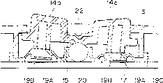
Comprise with reference to Fig. 1,6 and 7, the first control sections 9: one is substantially criss-cross pit 10, and it is formed on the round nose (right-hand member among Fig. 1 and 2) of housing 3; Four mark 11a, 11b, 11c and 11d, it is formed at upper end, lower end, right-hand member and the left end of pit 10, and is suitable for the directing object travel direction; And the monoblock type key body 12 with four key elements, these four key elements are installed in the inboard of correspondence markings 11a to 11d and stretch out through four corresponding opening respectively.
With reference to Fig. 6 and 7, key body 12 comprises: a circular base 13; Four key elements 14a, 14b, 14c and 14d are integrally formed in the upper surface of pedestal 13; Semisphere first pit 15 is formed on the center of pedestal 13 lower surfaces and is suitable for matching with supporting member 20; Semisphere second pit 16 is formed on the center of pedestal 13 upper surfaces and is suitable for matching with the projection 23 of center key supporting 22; And a contact guidance part 17, extend downwards and be suitable for being pressed on the back side of moving contact 19A from pedestal 13.
As among Fig. 6 more clearly shown in, each of four key elements 14a to 14d is extended and is had a pentagonal shape from the upper surface of pedestal 13.Each key elements also is that outer peripheral edges taper and its thickness mind-set pedestal 13 from pedestal 13 become greatly.The key elements 14a to 14d of key body extends upward through each opening 21 from housing 3 respectively.
Rotating shaft part 20 is spherical, is placed on the center of key body 12, and corresponding with center key supporting member 22 on the position.Supporting member 20 matches with first pit 15.
For the key body 12 that is installed in the housing, each of key elements is radially extended from center key supporting member 22.Each of key elements all has pentagonal shape.Key elements has such height adjacent to the part of center key supporting, so that the user can be with its doigte to the difference in height between key elements and the center key supporting member 22.The height of key elements increases along the direction away from center key supporting member 22.
When went up at the center (that is, center key supporting member 22) that the user is put into first control section 9 to finger, because in height different of the center of first control section and each key elements, the user can easily determine that with its finger tip the position concerns.The height edge of each top surface of key elements 14a to 14d is away from increasing gradually on the direction at the first control section center.When user's finger tip when the inner end of each key elements slides to the outer end, this structure be easy to guide user's finger tip and make that the user can the identification key element which be depressed.
In described embodiment, the center key supporting member 22 in the center of first control section has flat top.Perhaps, it can have round top 22a, shown in the dotted line among Fig. 7, so that make the user easily discern center key supporting member 22 with its finger.Or else, it can have a groove or a projection.
When not using first control section 9, elastic body 18 upwards promotes contact guidance part 17, and thereby upwards promote key body 12 so that realize semisphere second pit 16 of key body 12 and the engagement of the hemispherical bumps 23 of center key supporting member 22, as shown in Figure 8.At this moment, the ring edge of pedestal 13 is meshed with the edge of opening 21.The original position of Here it is key body 12, wherein key elements 14a to 14d stretches out housing 3.
For example, when key elements 14c when the direction of arrow A shown in Fig. 9 or B is depressed, first pit 15 of key body 12 is realized the engagement with spherical rotating shaft part 20.Key body 12 slides into the right of Fig. 9 on the spherical surface of rotating shaft part 20 then, thereby depresses elastic body 18.As a result, elastic body 18 is subjected to bending and causes moving contact 19A motion with the fixed contact 19B below this moving contact 19A.
As shown in Figure 10, when further the pressing down of key elements 14c, first pit 15 of key body 12 continues to slide on the spherical surface of rotating shaft part 20.This causes electrically contacting between moving contact 19A and the fixed contact 19B.
When key elements 14c was released, first pit 15 left spherical rotating shaft part 20 under the effect of elastic body 18.That is key elements 14c is flapped toward the left side among Figure 10.As a result, moving contact 19A and fixed contact 19B be separated (Fig. 9).The engagement of 16 realizations of second pit and projection 23 then.At last, key elements 14c returns its original position (Fig. 8) when rotating in the counterclockwise direction.
As shown in Figure 7, when being depressed, elastic body 18 is subjected to bending, causes first pit 15 to slide on the spherical surface of rotating shaft part 20 along forwards (in Fig. 7 by the c indicated direction on) as key elements 14a.As a result, the downward forward movement of key elements 14a realizes electrically contacting.This operation is no longer described with identical with reference to Fig. 8 to 10 the operation described herein.
Along with being in contact with one another of spherical pit and ball bearings, the key elements in first control section is bearing on the supporting member 20 and so swings so that realize electrically contacting.Because key elements 14a to 14d is arranged in the housing independently, they can be along any directions rather than only are depressed along a direction.This can make switching manipulation steadily and prevent key body 12 not steadily, skew and distortion.
As among Fig. 3 more clearly shown in, the first action gauge tap 27 comprise four independently, be positioned at the switch up and down of all corresponding end of cruciform pit 25.Key elements 28a to 28d extends upward a little corresponding to these switches and from the surface of pit 25.
Each includes mark key elements 28a to 28d, as square mark, cruciform mark, circular mark and triangular marker, thereby allows easily to discern its function.
In described embodiment, last key elements 28a, right button element 28b, following key elements 28c and left button element 28d be a given square mark, a cruciform mark, a circular mark and a triangular marker respectively.
Specify circle and cruciform to be labeled as specific key elements, these key elements are handled by user's the right hand according to given programmed instruction is the easiest, and they are subjected to frequent use.This layout makes essential switch that the user can easily discern minimum number determining that answer is " being (YES) " still " denying (NO) ", even also be like this when providing a large amount of switch.
For housing 3 and key elements are differentiated, key elements can be painted.
Third and fourth control section 29 and 30 will be described below.All comprise referring to figs. 1 through 3, the third and fourth control sections 29 and 30 every parts: upper and lower elongated open 31, they extend in parallel to each other and are respectively formed in the preceding protrusion side of preceding side body of first and second control sections 9 and 24; And second action gauge tap 33A and 33B, they have elongated key elements 32a and 32b and 34a and 34b respectively, and are contained within separately the opening 31 and extend forward through separately opening 31.
With reference to Figure 4 and 5, second action gauge tap 33A and the 33B is used to be provided at third and fourth control section 30 on housing 3 front sides and 29 switch.As among Fig. 4 more clearly shown in, second action gauge tap 33A and the 33B be symmetry in the horizontal, and includes the upper and lower key elements 34a of pair of parallel and the upper and lower key elements 32a and the 32b of 34b and pair of parallel respectively.Therefore, provide four switches altogether.These four switches are given (rught-down) mark of the right side-go up (right-up) mark, right side-down, left side-go up (left-up) mark and a left side-(left-down) down respectively, can travel direction with directing object.
Right-go up key elements 34a and right side-following key elements 34b can right-handed respectively forefinger and middle finger handle simultaneously, and meanwhile, left-last key elements 32a and a left side-following key elements 32b can left-handed respectively forefinger and middle finger handle simultaneously.But, be not necessary with these finger control key elements 32a, 32b and 34a, 34b.Perhaps, the user can come joystick key element 32a and 34a and key elements 32b and 34b with the forefinger of the right hand and left hand.
And when first and second handles 4 and 5 were held by two palms, the first, second, third and the 4th control section 9,24,29 and 30 with the hands ten more than finger was handled simultaneously.These control sections can only be handled with combining of both hands with a hand or with a hand.Thereby the present invention has improved operability, and is suitable for the advanced electronic recreation of object at three-dimensional space motion.
Use the controller unit of high operability, the user can have a part or combination in any in the controller unit 1 of the first, second, third and the 4th control section 9,24,29 and 30 by operation, enjoys virtual authenticity by the three dimensions recreation.
Therefore, the present invention is specially adapted to comprise aircraft or the submarine 3d gaming as material object.
For example, when the key elements 14a and the 4th control section of first control section 9 the right side-when following key elements 32b was depressed, aircraft travelled forward when rotating in the clockwise direction.
As the key elements 14a of first control section 9 with 14b is depressed simultaneously and the right side of the 3rd control section 29-when going up key elements 32b and also being depressed, aircraft moves right when rotating in the clockwise direction.
When the key elements 14a of first control section 9, the right side of the 3rd control section 29-go up key elements 32a, and the left side of the 4th control section 30-go up key elements 34a were depressed simultaneously, aircraft moved upward.If these key elements continue to be depressed, then aircraft can rotate when moving upward.
By individually or combination in any depress four monoblock type key elements 14a to 14d of first control section 9, just can carry out 16 kinds of operator schemes.In addition, by individually or combination in any depress two the key elements 34a and the 34b of two independent keys element 32a of the 3rd control section 29 and 32b and the 4th control section 30,16 kinds of operator schemes also are possible.Therefore, in three dimensions, can always have 256 kinds of operator schemes.
This layout is efficiently with in the three dimensional constitution motion fight or the object in the similar recreation.For example, bimanual forefinger is depressed the right side-last key elements 32a of the 3rd control section 29 and a left side-last key elements 34a of the 4th control section 30, thereby the first half of moving object (personage), say exactly, be exactly both hands, bimanual middle finger is depressed the right side-following key elements 32b and a left side-following key elements 34b simultaneously, thus the latter half of moving object (personage), specifically, leg for example.This makes the personage impact the adversary with his both legs or both hands, and can also move in complexity or three-dimensional mode.Certainly should be understood that key elements 32a, 32b, 34a and 34b can only handle with forefinger.
The present invention allows to use as the existing two-dimensional recreation and is the program of 3d gaming preparation.For the housing of bimanual palm supporting,, can be freely come object in the motion three dimensions with ten more than finger according to advanced procedures.
The invention is not restricted to the embodiments described.Certainly should be understood that and to revise key elements according to the games that provide.
Claims (14)
1. controller unit that is used to control electronic installation comprises:
A housing;
A pair of fork each other and from the handle of described housing towards the operator, the handle of described fork contacts with operator's both hands and is being supported by operator's both hands; And
By first and second control sections that operator's finger is handled, described first and second control sections are arranged on the described housing upper surface and are connected respectively to described handle to last.
2. according to the controller unit of claim 1, also comprise third and fourth control section, described third and fourth control section is arranged on the front side of described housing and lays respectively at the place ahead of described first and second control sections.
3. according to the controller unit of claim 2, the handle of wherein said fork and described housing are molded as a cell cube, and wherein said housing, described handle and the described first, second, third and the 4th control section are dimensioned and are arranged to allow operator's finger to handle the described first, second, third and the 4th control section, and housing is by the described handle supporting in operator's palm.
4. according to each controller unit of claim 1 to 3, wherein, when described housing was placed on the surface, the orientation of described first and second control sections was parallel to the described surface of placing described housing substantially.
5. according to each controller unit in the claim 1 to 3, wherein, described first control section comprises a plurality of key elements, and each of described a plurality of key elements all extends upward from described housing.
6. according to each controller unit in the claim 1 to 3, wherein, described first control section comprises a plurality of key elements, and described housing has one and is substantially criss-cross pit, this pit on the position corresponding to described a plurality of monoblock type key elements.
7. according to the controller unit of claim 2 or 3, wherein, described third and fourth control section extends from the front side of described housing.
8. according to the controller unit of claim 2 or 3, wherein, each part of described third and fourth control section includes one and goes up operating key and a following operating key.
9. according to each controller unit in the claim 1 to 3, wherein, described second control section includes the not isolabeling or the color of its function of indication.
10. according to each controller unit in the claim 1 to 3, wherein said housing has a upper surface, and described first and second control sections comprise that two separate each other and are installed in thumb starting switch on the described upper surface, each is adjacent with a handle, and described handle extends down from described upper surface is oblique.
11. according to the controller unit of claim 6, wherein, described a plurality of key elements diminish gradually to the described center that is substantially criss-cross pit.
12., wherein, describedly be substantially the mark that criss-cross pit includes the function that is suitable for indicating each key elements according to the controller unit of claim 6.
13. according to the controller unit of claim 6, wherein, the described center of criss-cross pit that is substantially is through handling so that discern its center.
14. one kind comprises the game machine according to each described controller unit in the claim 1 to 13.
Applications Claiming Priority (6)
| Application Number | Priority Date | Filing Date | Title |
|---|---|---|---|
| JP094988/94 | 1994-05-09 | ||
| JP094988/1994 | 1994-05-09 | ||
| JP9498894 | 1994-05-09 | ||
| JP238898/1994 | 1994-10-03 | ||
| JP238898/94 | 1994-10-03 | ||
| JP23889894A JP3628358B2 (en) | 1994-05-09 | 1994-10-03 | Game console controller |
Related Child Applications (1)
| Application Number | Title | Priority Date | Filing Date |
|---|---|---|---|
| CNB021015163A Division CN1278346C (en) | 1994-05-09 | 1995-05-08 | Controller unit for electronic device |
Publications (2)
| Publication Number | Publication Date |
|---|---|
| CN1124855A CN1124855A (en) | 1996-06-19 |
| CN1124544C true CN1124544C (en) | 2003-10-15 |
Family
ID=26436217
Family Applications (2)
| Application Number | Title | Priority Date | Filing Date |
|---|---|---|---|
| CN95105485A Expired - Lifetime CN1124544C (en) | 1994-05-09 | 1995-05-08 | Controller unit for electronic devices |
| CNB021015163A Expired - Lifetime CN1278346C (en) | 1994-05-09 | 1995-05-08 | Controller unit for electronic device |
Family Applications After (1)
| Application Number | Title | Priority Date | Filing Date |
|---|---|---|---|
| CNB021015163A Expired - Lifetime CN1278346C (en) | 1994-05-09 | 1995-05-08 | Controller unit for electronic device |
Country Status (11)
| Country | Link |
|---|---|
| US (3) | US5551693A (en) |
| EP (3) | EP0682350B1 (en) |
| JP (1) | JP3628358B2 (en) |
| KR (3) | KR100466578B1 (en) |
| CN (2) | CN1124544C (en) |
| AT (3) | ATE225564T1 (en) |
| AU (1) | AU700701B2 (en) |
| CA (2) | CA2148188C (en) |
| DE (3) | DE69533209T2 (en) |
| HK (2) | HK1013519A1 (en) |
| MY (1) | MY119408A (en) |
Families Citing this family (172)
| Publication number | Priority date | Publication date | Assignee | Title |
|---|---|---|---|---|
| US6343991B1 (en) * | 1997-10-01 | 2002-02-05 | Brad A. Armstrong | Game control with analog pressure sensor |
| US6222525B1 (en) * | 1992-03-05 | 2001-04-24 | Brad A. Armstrong | Image controllers with sheet connected sensors |
| JP3628358B2 (en) * | 1994-05-09 | 2005-03-09 | 株式会社ソニー・コンピュータエンタテインメント | Game console controller |
| US5820462A (en) * | 1994-08-02 | 1998-10-13 | Nintendo Company Ltd. | Manipulator for game machine |
| US6241611B1 (en) | 1995-05-10 | 2001-06-05 | Nintendo Co., Ltd. | Function expansion device and operating device using the function expansion device |
| DE69625523T2 (en) * | 1995-05-10 | 2003-07-10 | Nintendo Co Ltd | Control unit with analog joystick |
| US5963196A (en) * | 1995-05-10 | 1999-10-05 | Nintendo Co., Ltd. | Image processing system utilizing analog joystick |
| JP3544268B2 (en) | 1995-10-09 | 2004-07-21 | 任天堂株式会社 | Three-dimensional image processing apparatus and image processing method using the same |
| US6283857B1 (en) | 1996-09-24 | 2001-09-04 | Nintendo Co., Ltd. | Three-dimensional image processing apparatus with enhanced automatic and user point of view control |
| JP3524247B2 (en) | 1995-10-09 | 2004-05-10 | 任天堂株式会社 | Game machine and game machine system using the same |
| EP0797139B1 (en) | 1995-10-09 | 2003-06-18 | Nintendo Co., Limited | Three-dimensional image processing system |
| US6007428A (en) * | 1995-10-09 | 1999-12-28 | Nintendo Co., Ltd. | Operation controlling device and video processing system used therewith |
| JPH09167050A (en) * | 1995-10-09 | 1997-06-24 | Nintendo Co Ltd | Operation device and image processing system using the device |
| GB2313432B (en) | 1995-11-10 | 2000-06-21 | Nintendo Co Ltd | Joystick device |
| US5874956A (en) * | 1995-11-13 | 1999-02-23 | Platinum Technology | Apparatus and method for three dimensional manipulation of point of view and object |
| US6267673B1 (en) | 1996-09-20 | 2001-07-31 | Nintendo Co., Ltd. | Video game system with state of next world dependent upon manner of entry from previous world via a portal |
| US6155926A (en) | 1995-11-22 | 2000-12-05 | Nintendo Co., Ltd. | Video game system and method with enhanced three-dimensional character and background control |
| US6139433A (en) * | 1995-11-22 | 2000-10-31 | Nintendo Co., Ltd. | Video game system and method with enhanced three-dimensional character and background control due to environmental conditions |
| US6071191A (en) | 1995-11-22 | 2000-06-06 | Nintendo Co., Ltd. | Systems and methods for providing security in a video game system |
| US6022274A (en) | 1995-11-22 | 2000-02-08 | Nintendo Co., Ltd. | Video game system using memory module |
| US6190257B1 (en) | 1995-11-22 | 2001-02-20 | Nintendo Co., Ltd. | Systems and method for providing security in a video game system |
| EP0835676B1 (en) * | 1996-03-05 | 2004-10-13 | Sega Enterprises, Ltd. | Controller and extension unit for controller |
| CN1101570C (en) * | 1996-06-27 | 2003-02-12 | 俞祖祯 | Keyboard having 4 -state keys |
| US8674932B2 (en) * | 1996-07-05 | 2014-03-18 | Anascape, Ltd. | Image controller |
| US20040160414A1 (en) * | 1996-07-05 | 2004-08-19 | Armstrong Brad A. | Image controller |
| US6241610B1 (en) | 1996-09-20 | 2001-06-05 | Nintendo Co., Ltd. | Three-dimensional image processing system having dynamically changing character polygon number |
| US6139434A (en) * | 1996-09-24 | 2000-10-31 | Nintendo Co., Ltd. | Three-dimensional image processing apparatus with enhanced automatic and user point of view control |
| US6244959B1 (en) | 1996-09-24 | 2001-06-12 | Nintendo Co., Ltd. | Three-dimensional image processing system with enhanced character control |
| JPH114966A (en) * | 1996-10-01 | 1999-01-12 | Sony Computer Entateimento:Kk | Operation device for game machine and game device |
| US6231444B1 (en) * | 1996-10-11 | 2001-05-15 | Sony Computer Entertainment Inc. | Operating device for game machine |
| US6010406A (en) * | 1996-11-20 | 2000-01-04 | Alps Electric Co., Ltd. | Operation device for game machine |
| US5949401A (en) * | 1996-11-21 | 1999-09-07 | Kazarian; Randal N. | Two-handed input apparatus and method |
| SE510596C2 (en) * | 1996-11-27 | 1999-06-07 | Nassko Telecom Ab | COUPLING |
| US6525715B2 (en) * | 1997-03-24 | 2003-02-25 | Seiko Epson Corporation | Portable information acquisition device |
| US6641479B1 (en) * | 1997-04-24 | 2003-11-04 | Sony Computer Entertainment, Inc. | Control unit and system utilizing the control unit |
| JPH10295937A (en) * | 1997-04-24 | 1998-11-10 | Sony Computer Entertainment:Kk | Operation device for game machine |
| JP3442965B2 (en) * | 1997-04-25 | 2003-09-02 | 任天堂株式会社 | Video game system and storage medium for video game |
| US5764180A (en) * | 1997-06-30 | 1998-06-09 | Cummings; Thomas F. | Remote control keypad unit |
| US6057788A (en) * | 1997-06-30 | 2000-05-02 | Cummings; Thomas F. | Remote control keypad unit |
| JP3655438B2 (en) | 1997-07-17 | 2005-06-02 | 任天堂株式会社 | Video game system |
| US5874906A (en) * | 1997-09-22 | 1999-02-23 | Wilnel, Inc. | Data entry system |
| DE19746843A1 (en) * | 1997-10-23 | 1999-05-12 | Bosch Gmbh Robert | Multifunction button |
| US6068554A (en) * | 1997-11-25 | 2000-05-30 | Tyler; Kelly D. | Hand manipulated dual controller assembly |
| USD417665S (en) * | 1998-03-20 | 1999-12-14 | Sony Corporation | Remote controller |
| US6120025A (en) * | 1998-04-14 | 2000-09-19 | Hughes, Iv; Richard James-Patrick | Controller grip for a video game machine |
| JPH11342265A (en) * | 1998-06-01 | 1999-12-14 | Sony Computer Entertainment Inc | Record medium and entertainment system |
| USD417663S (en) * | 1998-06-05 | 1999-12-14 | Arista Interactive Llc | Controller for a game machine |
| US6288706B1 (en) | 1998-06-25 | 2001-09-11 | Micron Technology, Inc. | Method for operating an ergonomic keyboard |
| US6580421B1 (en) | 1998-06-25 | 2003-06-17 | Micron Technology, Inc. | Ergonomic keyboard |
| WO2000003407A1 (en) * | 1998-07-10 | 2000-01-20 | Sega Enterprises, Ltd. | Control switch device |
| US6225976B1 (en) | 1998-10-30 | 2001-05-01 | Interlink Electronics, Inc. | Remote computer input peripheral |
| JP3793659B2 (en) * | 1998-11-04 | 2006-07-05 | アルプス電気株式会社 | Game device input device |
| JP3853998B2 (en) | 1999-01-18 | 2006-12-06 | アルプス電気株式会社 | Operating device |
| US6409600B1 (en) * | 1999-05-13 | 2002-06-25 | Eleven Engineering Inc. | Game controllers keys |
| EP1058177A1 (en) | 1999-06-04 | 2000-12-06 | Alps Electric Co., Ltd. | Input device for game machine |
| JP2001043012A (en) * | 1999-07-27 | 2001-02-16 | Alps Electric Co Ltd | Signal input device |
| JP2001135198A (en) * | 1999-11-01 | 2001-05-18 | Sony Computer Entertainment Inc | Operating device for entertainment system and entertainment system having the operating device |
| JP2001143556A (en) * | 1999-11-12 | 2001-05-25 | Sony Computer Entertainment Inc | Operating device |
| US6524187B2 (en) * | 2000-01-14 | 2003-02-25 | Sony Computer Entertainment Inc. | Computer, method and recording medium for executing games using a pressure-sensitive controller |
| CN1322404C (en) * | 2000-02-07 | 2007-06-20 | 松下电器产业株式会社 | Track ball device and electronic apparatus using the same |
| JP4034504B2 (en) | 2000-07-31 | 2008-01-16 | アルプス電気株式会社 | Detection device |
| JP3866022B2 (en) | 2000-07-31 | 2007-01-10 | アルプス電気株式会社 | Operating device |
| JP3442374B2 (en) * | 2000-10-30 | 2003-09-02 | 株式会社ソニー・コンピュータエンタテインメント | Electronic equipment and input receiving device |
| EP1271276A1 (en) * | 2001-06-26 | 2003-01-02 | Koninklijke Philips Electronics N.V. | Control device of an electronic apparatus |
| JP3893940B2 (en) * | 2001-10-26 | 2007-03-14 | ミツミ電機株式会社 | controller |
| US7033176B2 (en) | 2002-07-17 | 2006-04-25 | Powergrid Fitness, Inc. | Motion platform system and method of rotating a motion platform about plural axes |
| US8313380B2 (en) | 2002-07-27 | 2012-11-20 | Sony Computer Entertainment America Llc | Scheme for translating movements of a hand-held controller into inputs for a system |
| US9393487B2 (en) | 2002-07-27 | 2016-07-19 | Sony Interactive Entertainment Inc. | Method for mapping movements of a hand-held controller to game commands |
| US20070015559A1 (en) * | 2002-07-27 | 2007-01-18 | Sony Computer Entertainment America Inc. | Method and apparatus for use in determining lack of user activity in relation to a system |
| US8570378B2 (en) | 2002-07-27 | 2013-10-29 | Sony Computer Entertainment Inc. | Method and apparatus for tracking three-dimensional movements of an object using a depth sensing camera |
| US7782297B2 (en) | 2002-07-27 | 2010-08-24 | Sony Computer Entertainment America Inc. | Method and apparatus for use in determining an activity level of a user in relation to a system |
| US6948948B2 (en) * | 2002-07-30 | 2005-09-27 | D&C Technology Co., Ltd. | PC cartridge having enhanced front connecting structure |
| US20040063502A1 (en) * | 2002-09-24 | 2004-04-01 | Intec, Inc. | Power module |
| US20040224768A1 (en) * | 2002-09-24 | 2004-11-11 | Saied Hussaini | Video game controller with integrated status indicators |
| US7121982B2 (en) * | 2002-12-04 | 2006-10-17 | Powergrid Fitness, Inc. | Computer interactive isometric exercise system and method for operatively interconnecting the exercise system to a computer system for use as a peripheral |
| US7727117B2 (en) | 2002-12-04 | 2010-06-01 | Ialabs-Ca, Llc | Method and apparatus for operatively controlling a virtual reality scenario with a physically demanding interface |
| US20040180719A1 (en) * | 2002-12-04 | 2004-09-16 | Philip Feldman | Game controller support structure and isometric exercise system and method of facilitating user exercise during game interaction |
| US7699755B2 (en) | 2002-12-04 | 2010-04-20 | Ialabs-Ca, Llc | Isometric exercise system and method of facilitating user exercise during video game play |
| US20040137984A1 (en) * | 2003-01-09 | 2004-07-15 | Salter Hal C. | Interactive gamepad device and game providing means of learning musical pieces and songs |
| TWM257867U (en) * | 2003-02-18 | 2005-03-01 | Zeroplus Technology Co Ltd | Game controller capable of adjusting resolution |
| JP4053912B2 (en) * | 2003-03-19 | 2008-02-27 | ミツミ電機株式会社 | Control adapter device |
| US20040259638A1 (en) * | 2003-06-18 | 2004-12-23 | Kramer Dan H. | Handheld controller with mouse-type control |
| US20050124387A1 (en) * | 2003-12-09 | 2005-06-09 | Ribeiro Claudio S. | Portable apparatus user interface |
| US8170945B2 (en) * | 2004-01-15 | 2012-05-01 | Bgc Partners, Inc. | System and method for providing security to a game controller device for electronic trading |
| US8469808B2 (en) * | 2004-01-15 | 2013-06-25 | Bgc Partners, Inc. | System and method for managing a game controller device for electronic trading |
| US7207885B2 (en) * | 2004-01-15 | 2007-04-24 | Espeed, Inc. | System and method for using a game controller device for electronic trading |
| US20050174337A1 (en) * | 2004-02-11 | 2005-08-11 | Nielsen Paul S. | Electronic handheld drawing and gaming system using television monitor |
| JP4268537B2 (en) * | 2004-02-20 | 2009-05-27 | アルプス電気株式会社 | Multi-directional input device |
| US20050277470A1 (en) * | 2004-06-14 | 2005-12-15 | Watanachote Susornpol J | Control unit for controlling a sophisticated character |
| US20060066565A1 (en) * | 2004-09-28 | 2006-03-30 | Kevin Manley | Controller apparatus |
| EP1818302B1 (en) * | 2004-11-29 | 2013-08-14 | Mitsubishi Denki Kabushiki Kaisha | Landing button device of elevator |
| US20060223634A1 (en) * | 2005-04-04 | 2006-10-05 | Philip Feldman | Game controller connection system and method of selectively connecting a game controller with a plurality of different video gaming systems |
| US20060247047A1 (en) * | 2005-04-14 | 2006-11-02 | Mitchell Michael J | Universal button module |
| US7331226B2 (en) * | 2005-05-20 | 2008-02-19 | Powergrid Fitness, Inc. | Force measurement system for an isometric exercise device |
| KR100706289B1 (en) * | 2005-08-19 | 2007-04-13 | 가부시키가이샤 도쿄 마루이 | Recoil shock device in toy gun |
| JP4805633B2 (en) * | 2005-08-22 | 2011-11-02 | 任天堂株式会社 | Game operation device |
| KR100746009B1 (en) * | 2005-10-26 | 2007-08-06 | 삼성전자주식회사 | Apparatus for navigation in 3-dimensional graphic user interface |
| US20070178966A1 (en) * | 2005-11-03 | 2007-08-02 | Kip Pohlman | Video game controller with expansion panel |
| US8108092B2 (en) | 2006-07-14 | 2012-01-31 | Irobot Corporation | Autonomous behaviors for a remote vehicle |
| USRE48417E1 (en) | 2006-09-28 | 2021-02-02 | Sony Interactive Entertainment Inc. | Object direction using video input combined with tilt angle information |
| US8310656B2 (en) | 2006-09-28 | 2012-11-13 | Sony Computer Entertainment America Llc | Mapping movements of a hand-held controller to the two-dimensional image plane of a display screen |
| US8781151B2 (en) | 2006-09-28 | 2014-07-15 | Sony Computer Entertainment Inc. | Object detection using video input combined with tilt angle information |
| US7843431B2 (en) * | 2007-04-24 | 2010-11-30 | Irobot Corporation | Control system for a remote vehicle |
| US20080096654A1 (en) * | 2006-10-20 | 2008-04-24 | Sony Computer Entertainment America Inc. | Game control using three-dimensional motions of controller |
| US20080228618A1 (en) | 2007-03-15 | 2008-09-18 | Noviello Joseph C | System And Method For Providing An Operator Interface For Displaying Market Data, Trader Options, And Trader Input |
| JP5427343B2 (en) | 2007-04-20 | 2014-02-26 | 任天堂株式会社 | Game controller |
| JP5427346B2 (en) | 2007-10-05 | 2014-02-26 | 任天堂株式会社 | Load detection program, load detection device, load detection system, and load detection method |
| JP5080196B2 (en) | 2007-10-09 | 2012-11-21 | 任天堂株式会社 | Program, information processing apparatus, information processing system, and information processing method |
| JP4382844B2 (en) | 2007-10-31 | 2009-12-16 | 任天堂株式会社 | Weighting machine for adjustment and weighting method for adjustment |
| CN101607138B (en) * | 2008-06-17 | 2013-11-20 | 盛乐信息技术(上海)有限公司 | Action recognition method based on finite automata model |
| JP5361349B2 (en) | 2008-11-28 | 2013-12-04 | 任天堂株式会社 | Information processing apparatus, computer program, information processing system, and information processing method |
| JP5806443B2 (en) | 2008-12-26 | 2015-11-10 | 任天堂株式会社 | Biological information management system |
| JP5271121B2 (en) | 2009-03-09 | 2013-08-21 | 任天堂株式会社 | Information processing program, information processing apparatus, information processing system, and information processing method |
| JP5436909B2 (en) | 2009-03-30 | 2014-03-05 | 任天堂株式会社 | Information processing program, information processing apparatus, information processing system, and information processing method |
| US8263889B2 (en) * | 2009-04-13 | 2012-09-11 | Sony Computer Entertainment Inc. | Manipulating apparatus and mobile terminal including the same |
| JP5290844B2 (en) * | 2009-04-13 | 2013-09-18 | 株式会社ソニー・コンピュータエンタテインメント | Operation device and portable terminal |
| JP5161182B2 (en) | 2009-09-28 | 2013-03-13 | 任天堂株式会社 | Information processing program and information processing apparatus |
| JP5610735B2 (en) | 2009-09-29 | 2014-10-22 | 任天堂株式会社 | Information processing program, information processing apparatus, information processing method, and information processing system |
| JP5496591B2 (en) | 2009-09-30 | 2014-05-21 | 任天堂株式会社 | Information processing program and information processing apparatus |
| US8803803B2 (en) * | 2011-01-25 | 2014-08-12 | Sony Corporation | Operation member provided in electronic device, and electronic device |
| CN102671375B (en) * | 2011-03-09 | 2015-06-03 | 台达电子工业股份有限公司 | Key controller |
| US8641525B2 (en) * | 2011-06-17 | 2014-02-04 | Ironburg Inventions Ltd. | Controller for video game console |
| US9586115B1 (en) * | 2011-08-18 | 2017-03-07 | Kid Group, Llc | 3D game |
| AT512033B1 (en) * | 2011-12-12 | 2013-05-15 | Lunatone Ind Elektronik Gmbh | SWITCH |
| CL2013001253S1 (en) * | 2013-02-19 | 2014-02-21 | Sony Computer Entertainment Inc | Control unit |
| US10203768B2 (en) * | 2013-09-20 | 2019-02-12 | Franklin Donald Ruffin | Blind key pad |
| FR3019759B1 (en) * | 2014-04-15 | 2021-12-17 | Playrapid | CONTROL INPUT DEVICE FOR AN ELECTRONIC / COMPUTER DEVICE |
| US9302183B2 (en) * | 2014-04-25 | 2016-04-05 | Cheng Uei Precision Industry Co., Ltd. | Push-button structure |
| US9804696B2 (en) | 2015-01-02 | 2017-10-31 | Microsoft Technology Licensing, Llc | User-input control device toggled motion tracking |
| US10463979B2 (en) | 2015-06-09 | 2019-11-05 | Collective Minds Gaming Co. Ltd. | Adapter for attachment to a game controller |
| CA162784S (en) | 2015-06-09 | 2016-11-02 | Collective Minds Gaming Co Ltd | Adapter for video game controller |
| US9724601B2 (en) | 2015-06-12 | 2017-08-08 | Nintendo Co., Ltd. | Game controller |
| JP6083884B2 (en) * | 2015-06-12 | 2017-02-22 | 任天堂株式会社 | Support device, charging device, and operation system |
| USD784988S1 (en) * | 2015-10-29 | 2017-04-25 | Microsoft Corporation | Controller with removeable thumbstick attachment |
| USD784986S1 (en) * | 2015-10-29 | 2017-04-25 | Microsoft Corporation | Thumbstick for a controller |
| USD794024S1 (en) * | 2015-10-29 | 2017-08-08 | Microsoft Corporation | Directional pad for a controller |
| USD784335S1 (en) * | 2015-10-29 | 2017-04-18 | Microsoft Corporation | Controller with removeable paddles |
| USD794026S1 (en) * | 2015-10-29 | 2017-08-08 | Microsoft Corporation | Set of paddles for a controller |
| USD784989S1 (en) * | 2015-10-29 | 2017-04-25 | Microsoft Corporation | Controller |
| USD784987S1 (en) * | 2015-10-29 | 2017-04-25 | Microsoft Corporation | Controller |
| USD794025S1 (en) * | 2015-10-29 | 2017-08-08 | Microsoft Corporation | Controller with removeable directional pad |
| CN105413173B (en) * | 2015-12-18 | 2018-09-18 | 江苏易乐网络科技有限公司 | A kind of multifunctional controller |
| CN105413174B (en) * | 2015-12-18 | 2019-02-19 | 江苏易乐网络科技有限公司 | A kind of deformable controller |
| CN105788938B (en) * | 2016-04-20 | 2018-05-08 | 常州市凯迪电器股份有限公司 | One key multi-control type hand controller structure |
| USD799599S1 (en) | 2016-05-13 | 2017-10-10 | Microsoft Corporation | Controller |
| USD794129S1 (en) | 2016-05-13 | 2017-08-08 | Microsoft Corporation | Controller |
| USD794717S1 (en) | 2016-05-13 | 2017-08-15 | Microsoft Corporation | Controller |
| USD795351S1 (en) | 2016-06-09 | 2017-08-22 | Microsoft Corporation | Controller |
| USD795350S1 (en) | 2016-06-09 | 2017-08-22 | Microsoft Corporation | Controller |
| JP6677580B2 (en) | 2016-06-10 | 2020-04-08 | 任天堂株式会社 | Game controller |
| JP6893763B2 (en) | 2016-06-10 | 2021-06-23 | 任天堂株式会社 | Game controller |
| JP7083226B2 (en) * | 2016-06-10 | 2022-06-10 | 任天堂株式会社 | Game controller |
| EP3254739B1 (en) | 2016-06-10 | 2020-03-25 | Nintendo Co., Ltd. | Game controller |
| JP6782567B2 (en) | 2016-06-10 | 2020-11-11 | 任天堂株式会社 | Game controller |
| EP3473310B1 (en) | 2016-06-10 | 2020-01-22 | Nintendo Co., Ltd. | Game controller |
| USD795960S1 (en) | 2016-07-14 | 2017-08-29 | Microsoft Corporation | Controller |
| USD819641S1 (en) | 2016-08-30 | 2018-06-05 | Nintendo Co., Ltd. | Controller for computer |
| JP6730918B2 (en) * | 2016-12-09 | 2020-07-29 | 株式会社ホリ | Controller, cover member |
| JP6795623B2 (en) | 2017-01-11 | 2020-12-02 | 株式会社ソニー・インタラクティブエンタテインメント | controller |
| US10507385B2 (en) | 2017-01-25 | 2019-12-17 | Kieran S. Lyden | Game controller |
| USD816170S1 (en) | 2017-04-06 | 2018-04-24 | Microsoft Corporation | Controller |
| USD816773S1 (en) | 2017-04-06 | 2018-05-01 | Microsoft Corporation | Controller |
| USD825005S1 (en) | 2017-04-06 | 2018-08-07 | Microsoft Corporation | Controller |
| USD831648S1 (en) * | 2017-06-08 | 2018-10-23 | Razer (Asia-Pacific) Pte. Ltd. | Game controller |
| USD872183S1 (en) | 2018-06-08 | 2020-01-07 | Microsoft Corporation | Controller |
| CN108905196A (en) * | 2018-08-16 | 2018-11-30 | 南昌黑鲨科技有限公司 | A kind of game paddle and application thereof |
| USD934343S1 (en) | 2019-01-15 | 2021-10-26 | Collective Minds Gaming Co. Ltd. | Video game controller accessory |
| JP7185611B2 (en) * | 2019-10-30 | 2022-12-07 | 東洋電装株式会社 | seesaw switch |
| CN116635117B (en) * | 2020-12-17 | 2024-03-01 | 雷蛇(亚太)私人有限公司 | Direction pad assembly and handheld controller |
| USD983200S1 (en) | 2021-02-08 | 2023-04-11 | Collective Minds Gaming Co. Ltd. | Stop for a trigger button of a video game controller |
| CA201150S (en) | 2021-02-08 | 2022-10-19 | Collective Minds Gaming Co Ltd | Adapter for a video game controller |
| CN113571358B (en) * | 2021-07-26 | 2023-12-22 | 歌尔科技有限公司 | Trigger button device, electronic equipment and electronic system |
Citations (4)
| Publication number | Priority date | Publication date | Assignee | Title |
|---|---|---|---|---|
| US4687200A (en) * | 1983-08-05 | 1987-08-18 | Nintendo Co., Ltd. | Multi-directional switch |
| WO1990015427A1 (en) * | 1989-06-02 | 1990-12-13 | Atari Corporation | Multi-directional switch assembly |
| EP0470615A1 (en) * | 1990-08-09 | 1992-02-12 | Nintendo Co., Ltd. | Controller for a game machine |
| US5294121A (en) * | 1993-06-04 | 1994-03-15 | Txc Corporation | Direction control key assembly |
Family Cites Families (14)
| Publication number | Priority date | Publication date | Assignee | Title |
|---|---|---|---|---|
| US3428747A (en) * | 1965-03-22 | 1969-02-18 | Nicholas Alferieff | Man to machine communication keyboard device |
| US4469330A (en) * | 1982-01-07 | 1984-09-04 | Atari, Inc. | Controller unit for video game |
| JPS61194231A (en) * | 1985-02-22 | 1986-08-28 | ユニチカ株式会社 | Production of crimped processed yarn comprising multilayeredstructure |
| JPH04104893A (en) * | 1990-08-24 | 1992-04-07 | Takeshi Hayashi | Water purifying device |
| JP2669226B2 (en) * | 1991-09-25 | 1997-10-27 | 株式会社島津製作所 | Capillary electrophoresis device |
| JPH0623148A (en) * | 1992-02-24 | 1994-02-01 | Shinichi Tsubota | Game controller |
| JP2638395B2 (en) * | 1992-06-30 | 1997-08-06 | 株式会社セガ・エンタープライゼス | Control key device |
| JPH0617070A (en) * | 1992-07-01 | 1994-01-25 | Ube Ind Ltd | Solid fuel |
| JPH0638137A (en) * | 1992-07-13 | 1994-02-10 | Sanyo Electric Co Ltd | Audio signal reproduction device |
| US5283401A (en) * | 1992-07-30 | 1994-02-01 | Schmucker Charles J | Multiple switch assembly including lockable and/or vertically movable switch actuator |
| DE9210286U1 (en) * | 1992-07-31 | 1992-09-24 | Blaupunkt-Werke Gmbh, 3200 Hildesheim, De | |
| DE69315149T2 (en) * | 1992-09-09 | 1998-05-07 | Matsushita Electric Ind Co Ltd | Combination pressure switch arrangement |
| JP2777763B2 (en) * | 1992-09-30 | 1998-07-23 | 株式会社 セガ・エンタープライゼス | Control key device |
| JP3628358B2 (en) * | 1994-05-09 | 2005-03-09 | 株式会社ソニー・コンピュータエンタテインメント | Game console controller |
-
1994
- 1994-10-03 JP JP23889894A patent/JP3628358B2/en not_active Expired - Lifetime
-
1995
- 1995-04-28 CA CA002148188A patent/CA2148188C/en not_active Expired - Lifetime
- 1995-04-28 AU AU17672/95A patent/AU700701B2/en not_active Expired
- 1995-04-28 CA CA002487191A patent/CA2487191C/en not_active Expired - Lifetime
- 1995-05-02 MY MYPI95001145A patent/MY119408A/en unknown
- 1995-05-08 CN CN95105485A patent/CN1124544C/en not_active Expired - Lifetime
- 1995-05-08 CN CNB021015163A patent/CN1278346C/en not_active Expired - Lifetime
- 1995-05-08 KR KR1019950011109A patent/KR100466578B1/en not_active IP Right Cessation
- 1995-05-08 US US08/436,728 patent/US5551693A/en not_active Expired - Lifetime
- 1995-05-09 DE DE69533209T patent/DE69533209T2/en not_active Expired - Lifetime
- 1995-05-09 EP EP95106977A patent/EP0682350B1/en not_active Expired - Lifetime
- 1995-05-09 EP EP04010235A patent/EP1443536B1/en not_active Expired - Lifetime
- 1995-05-09 DE DE69536021T patent/DE69536021D1/en not_active Expired - Lifetime
- 1995-05-09 EP EP02004006A patent/EP1213731B1/en not_active Expired - Lifetime
- 1995-05-09 AT AT95106977T patent/ATE225564T1/en active
- 1995-05-09 AT AT04010235T patent/ATE449413T1/en not_active IP Right Cessation
- 1995-05-09 DE DE69528412T patent/DE69528412T2/en not_active Expired - Lifetime
- 1995-05-09 AT AT02004006T patent/ATE270000T1/en active
-
1996
- 1996-07-17 US US08/682,271 patent/US5716274A/en not_active Expired - Lifetime
-
1997
- 1997-05-28 US US08/864,556 patent/US5853326A/en not_active Expired - Lifetime
-
1998
- 1998-12-22 HK HK98114889A patent/HK1013519A1/en not_active IP Right Cessation
-
2002
- 2002-07-27 HK HK02105533A patent/HK1044222A1/en not_active IP Right Cessation
-
2004
- 2004-07-22 KR KR1020040057250A patent/KR100647149B1/en not_active IP Right Cessation
- 2004-10-18 KR KR1020040083221A patent/KR100499661B1/en not_active IP Right Cessation
Patent Citations (4)
| Publication number | Priority date | Publication date | Assignee | Title |
|---|---|---|---|---|
| US4687200A (en) * | 1983-08-05 | 1987-08-18 | Nintendo Co., Ltd. | Multi-directional switch |
| WO1990015427A1 (en) * | 1989-06-02 | 1990-12-13 | Atari Corporation | Multi-directional switch assembly |
| EP0470615A1 (en) * | 1990-08-09 | 1992-02-12 | Nintendo Co., Ltd. | Controller for a game machine |
| US5294121A (en) * | 1993-06-04 | 1994-03-15 | Txc Corporation | Direction control key assembly |
Also Published As
Similar Documents
| Publication | Publication Date | Title |
|---|---|---|
| CN1124544C (en) | Controller unit for electronic devices | |
| CN1239219C (en) | Operation device for game computer | |
| CN1139417C (en) | Actuating device for game machine | |
| CN1153576A (en) | Operating device with analog joystick | |
| US10238963B2 (en) | Adjustable tension thumbstick | |
| US6010406A (en) | Operation device for game machine | |
| US9943757B2 (en) | Adjustable tension thumbstick | |
| CN1919395A (en) | Game operating device | |
| CN113117313B (en) | Game Controller | |
| JP2012055339A (en) | Controller | |
| JP2003236246A (en) | Operating device for game machine | |
| TW201913302A (en) | Input device and method of operating the same | |
| EP2902082A1 (en) | Video games input device | |
| EP2298425B1 (en) | Operation device | |
| JP3628617B2 (en) | Game console controller | |
| AU738517B2 (en) | Controller unit for electronic devices |
Legal Events
| Date | Code | Title | Description |
|---|---|---|---|
| C06 | Publication | ||
| PB01 | Publication | ||
| C10 | Entry into substantive examination | ||
| SE01 | Entry into force of request for substantive examination | ||
| C53 | Correction of patent of invention or patent application | ||
| CB02 | Change of applicant information |
Applicant after: Sony Computer Entertainment Inc. Applicant before: Sony Corporation |
|
| COR | Change of bibliographic data |
Free format text: CORRECT: APPLICANT; FROM: SONY CORP. TO: SONY COMPUTER ENTERTAINMENT INC. |
|
| C14 | Grant of patent or utility model | ||
| GR01 | Patent grant | ||
| C17 | Cessation of patent right | ||
| CX01 | Expiry of patent term |
Expiration termination date: 20150508 Granted publication date: 20031015 |