JP6730918B2 - Controller, cover member - Google Patents
Controller, cover member Download PDFInfo
- Publication number
- JP6730918B2 JP6730918B2 JP2016239434A JP2016239434A JP6730918B2 JP 6730918 B2 JP6730918 B2 JP 6730918B2 JP 2016239434 A JP2016239434 A JP 2016239434A JP 2016239434 A JP2016239434 A JP 2016239434A JP 6730918 B2 JP6730918 B2 JP 6730918B2
- Authority
- JP
- Japan
- Prior art keywords
- cover
- controller
- push button
- button input
- fixing portion
- Prior art date
- Legal status (The legal status is an assumption and is not a legal conclusion. Google has not performed a legal analysis and makes no representation as to the accuracy of the status listed.)
- Expired - Fee Related
Links
- 238000000034 method Methods 0.000 claims description 6
- 239000011347 resin Substances 0.000 claims description 4
- 229920005989 resin Polymers 0.000 claims description 4
- 230000005484 gravity Effects 0.000 claims description 3
- 238000013461 design Methods 0.000 description 6
- 230000002093 peripheral effect Effects 0.000 description 5
- 238000003825 pressing Methods 0.000 description 3
- 230000000694 effects Effects 0.000 description 2
- 230000006870 function Effects 0.000 description 2
- 230000002452 interceptive effect Effects 0.000 description 2
- 239000000463 material Substances 0.000 description 2
- 239000002184 metal Substances 0.000 description 2
- 230000035807 sensation Effects 0.000 description 2
- 239000000853 adhesive Substances 0.000 description 1
- 230000001070 adhesive effect Effects 0.000 description 1
- 238000013459 approach Methods 0.000 description 1
- 238000007429 general method Methods 0.000 description 1
- 230000015541 sensory perception of touch Effects 0.000 description 1
- 239000007787 solid Substances 0.000 description 1
Images


Classifications
-
- A—HUMAN NECESSITIES
- A63—SPORTS; GAMES; AMUSEMENTS
- A63F—CARD, BOARD, OR ROULETTE GAMES; INDOOR GAMES USING SMALL MOVING PLAYING BODIES; VIDEO GAMES; GAMES NOT OTHERWISE PROVIDED FOR
- A63F13/00—Video games, i.e. games using an electronically generated display having two or more dimensions
- A63F13/20—Input arrangements for video game devices
- A63F13/24—Constructional details thereof, e.g. game controllers with detachable joystick handles
-
- A—HUMAN NECESSITIES
- A63—SPORTS; GAMES; AMUSEMENTS
- A63F—CARD, BOARD, OR ROULETTE GAMES; INDOOR GAMES USING SMALL MOVING PLAYING BODIES; VIDEO GAMES; GAMES NOT OTHERWISE PROVIDED FOR
- A63F13/00—Video games, i.e. games using an electronically generated display having two or more dimensions
- A63F13/90—Constructional details or arrangements of video game devices not provided for in groups A63F13/20 or A63F13/25, e.g. housing, wiring, connections or cabinets
- A63F13/98—Accessories, i.e. detachable arrangements optional for the use of the video game device, e.g. grip supports of game controllers
-
- G—PHYSICS
- G06—COMPUTING; CALCULATING OR COUNTING
- G06F—ELECTRIC DIGITAL DATA PROCESSING
- G06F3/00—Input arrangements for transferring data to be processed into a form capable of being handled by the computer; Output arrangements for transferring data from processing unit to output unit, e.g. interface arrangements
- G06F3/01—Input arrangements or combined input and output arrangements for interaction between user and computer
- G06F3/03—Arrangements for converting the position or the displacement of a member into a coded form
- G06F3/033—Pointing devices displaced or positioned by the user, e.g. mice, trackballs, pens or joysticks; Accessories therefor
- G06F3/0338—Pointing devices displaced or positioned by the user, e.g. mice, trackballs, pens or joysticks; Accessories therefor with detection of limited linear or angular displacement of an operating part of the device from a neutral position, e.g. isotonic or isometric joysticks
-
- H—ELECTRICITY
- H01—ELECTRIC ELEMENTS
- H01H—ELECTRIC SWITCHES; RELAYS; SELECTORS; EMERGENCY PROTECTIVE DEVICES
- H01H25/00—Switches with compound movement of handle or other operating part
- H01H25/04—Operating part movable angularly in more than one plane, e.g. joystick
-
- H—ELECTRICITY
- H01—ELECTRIC ELEMENTS
- H01H—ELECTRIC SWITCHES; RELAYS; SELECTORS; EMERGENCY PROTECTIVE DEVICES
- H01H3/00—Mechanisms for operating contacts
- H01H3/02—Operating parts, i.e. for operating driving mechanism by a mechanical force external to the switch
Description
本発明は、コントローラ、例えば、家庭用のゲーム専用機であるゲーム機、或いはゲームを実行することができるパーソナルコンピュータに入力を行うためのコントローラに関する。 The present invention relates to a controller, for example, a game machine which is a dedicated game machine for home use, or a controller for inputting to a personal computer capable of executing a game.
かねてからビデオゲームが普及している。ユーザは、何らかの機器(プラットフォーム)を用いてビデオゲームを楽しむ。ビデオゲームを実行するプラットフォームには、据置型の家庭用のゲーム機、汎用のパーソナルコンピュータ、可搬のゲーム機、携帯電話、スマートフォン、ゲームセンターなどのアミューズメント施設に置かれたゲーム機等様々なものがある。
プラットフォームの如何によらず、プラットフォームを構成する機器に対して入力を行うための装置が必要であり、その大半は、コントローラとして実現されている。
Video games have been popular for some time. A user enjoys a video game using some device (platform). There are various platforms for running video games, such as stationary home-use game machines, general-purpose personal computers, portable game machines, mobile phones, smartphones, game machines installed in amusement facilities such as game centers, etc. There is.
Regardless of the platform, there is a need for a device for inputting to devices that make up the platform, most of which are implemented as controllers.
家庭用の据置型のゲーム機としては、例えば、株式会社ソニー・インタラクティブエンタテインメントが製造、販売を行うPlayStation 4(商標)や、日本マイクロソフト株式会社が製造、販売を行うXbox One(商標)がある。これらゲーム機は通常、専用品の純正コントローラが付属し又は別売りされており、ユーザは通常純正コントローラを用いてゲームを楽しむ。純正コントローラのデザインはかつては様々であったが、現在はある程度のドミナントデザインができている。そのドミナントデザインは、両手で把持できるような横長形状の本体を備え、本体の左半分に、例えば4方向のデジタル入力が可能な十字キーと、それを倒す方向により、例えばアナログ入力が可能なスティック入力装置とが、その右半分に4つの押しボタンと上記の如きスティック入力装置とが設けられる、というものである。 Examples of stationary game machines for home use include PlayStation 4 (trademark) manufactured and sold by Sony Interactive Entertainment Inc. and Xbox One (trademark) manufactured and sold by Microsoft Japan. These game machines usually come with a dedicated genuine controller or are sold separately, and the user usually enjoys the game using the genuine controller. The design of the genuine controller used to be various, but nowadays some dominant designs are available. Its dominant design has a horizontally long body that can be held with both hands, and on the left half of the body, a cross key that allows digital input in four directions, for example, and a stick that allows analog input depending on the direction in which it is tilted. The input device is such that four push buttons and the stick input device as described above are provided on the right half thereof.
もっとも、上述のドミナントデザインはすべてのコントローラで採用されているわけではない。例えば、上述の十字キーを、十字の4つのアームの例えば先端に当たる位置(正方形の4つの頂点に相当する位置とも言える。)に配した4つの押しボタンとしたコントローラも提案されている。
十字キーは通常、その4つのアームがユーザから見て前後左右に位置するようにされており、ユーザは前後左右の4種類の入力のいずれかを十字キーの4つのアームのいずれかの先端を押し込むことによって、任意に行うことができる。そして更には、十字キーの4つのアームの隣り合う任意の2つの中間を押し込むことによって、その2つのアームを同時に押すことも可能である。しかし、十字キーにはその原理上、隣り合わない、言い換えれば、反対側に位置する2つのアームを絶対に同時に押せない、という弱点がある。
十字キーに代えて4つの押しボタンを採用するとそのような弱点がなくなるため、十字キーに代えて4つの押しボタンを採用するということには一定の理がある。
However, the dominant design described above is not used in all controllers. For example, there is also proposed a controller having four push buttons in which the above-described cross key is arranged at positions corresponding to, for example, tips of four arms of the cross (also referred to as positions corresponding to four vertices of a square).
The four-way key is usually arranged so that its four arms are located in the front, rear, left, and right as seen from the user. It can be arbitrarily performed by pushing it. Further, it is also possible to push the two arms at the same time by pushing in the middle of any two adjacent four arms of the cross key. However, in principle, the cross key has a weak point that it is not adjacent to each other, in other words, the two arms located on the opposite side cannot be pressed at the same time.
If four push buttons are adopted instead of the cross key, such weak points will be eliminated, and therefore there is a certain reason to adopt four push buttons instead of the cross key.
とはいえ、ユーザは慣れ親しんだコントローラを好む。したがって、例えば十字キーに慣れ親しんだユーザが、十字キーを4つの押しボタンに置換したコントローラを使用すると、その違いからストレスを感じることがある。また、ユーザが実行しようとするゲームによっては、4つの押しボタンのうちの正方形の対角に位置する2つの押しボタンを同時に押し込むことがそのゲームにおける何らかの操作ミスに繋がるため、むしろ対角にある2つの押しボタンを同時に押せないようにした方が好ましい、ということも生じうる。
そのような点を考慮すると、十字キーに代わる4つの押しボタンを有するコントローラにおける4つの押しボタンを、基本はそのまま使用するにしても、ユーザの希望に合わせて、場合により、あたかも十字キーの如く操作することができるような技術が存在すればユーザの欲求に叶う。
しかしながら、そのような技術は今のところ知られていない。
However, users prefer familiar controllers. Therefore, for example, if a user who is familiar with the cross key uses a controller in which the cross key is replaced with four push buttons, the difference may cause stress. In addition, depending on the game that the user intends to execute, pushing two push buttons that are located diagonally of a square out of the four push buttons at the same time may lead to some operation error in the game, so it is rather diagonal. It may happen that it is preferable not to press two push buttons at the same time.
In consideration of such a point, even if the four push buttons in the controller having four push buttons instead of the cross key are used as they are, the push button may be changed to a cross key according to the user's wishes. If there is a technology that can be operated, it will satisfy the user's desire.
However, no such technique is known so far.
本願は、十字キーに代わる4つの押しボタンを有するコントローラにおける4つの押しボタンを、ユーザの希望に合わせて、場合により、あたかも十字キーの如く操作することができるようにするための技術を提供することをその課題とする。 The present application provides a technique for allowing four push buttons in a controller having four push buttons to replace the cross keys to be operated as if desired by the user, as occasion demands, like a cross key. That is the task.
本願発明者は、上述の課題を解決するために、以下のような発明を提案する。
本願発明は、正方形の頂点の位置にそれぞれ配置された、押込みにより入力を行う4つで一組の押しボタンを有する押しボタン入力部を、ユーザが把持する本体に備えているコントローラである。かかるコントローラは、背景技術の欄で述べた4つの押しボタンを有するコントローラに相当する。本願発明によるコントローラは、もっぱらゲーム用のコントローラであるが、そのプラットフォームとなる機器は問わない。
そして、このコントローラは、前記押しボタン入力部に対して着脱自在な固定を行えるようにされたカバー固定部と、前記カバー固定部が前記押しボタン入力部に対して固定されたときに前記押しボタン入力部における4つの前記押しボタンのすべてを少なくとも覆う、一体物とされ且つ板状とされたカバー部と、を備えたカバー部材を備えており、前記カバー固定部が前記本体に対して固定された状態で、前記カバー部の所定の位置を押し込むことにより、4つの前記押しボタンによる入力を行えるようになっている。
かかるコントローラは、カバー部材を備えている。カバー部材は、4つの押しボタンのすべてを少なくとも覆う一体物とされ且つ板状とされたカバー部を備えている。カバー部材は、また、コントローラの押しボタン入力部に対して着脱自在な固定を行えるようにされたカバー固定部を備えている。カバー固定部により、カバー部材がコントローラに取付けられたとき、カバー部は4つの押しボタンのすべてを覆う。この状態でユーザは、カバー部の所定の位置を押し込むことにより、言い換えればカバー部を傾けることにより、カバー部の下面に当接した任意の押しボタンを押し込むことが可能となり、それにより任意の押しボタンによる入力を行える。板状のカバー部の任意の場所を押し込む動作は、4つの押しボタンを個別に押し込む動作に比べれば、背景技術の欄で説明した十字キーのアームの先端を押し込む動作に近い。
したがって、ユーザは、カバー部材をコントローラの押しボタン入力部に対して固定したときには、4つの押しボタンを十字キーを操作するかのごとく操作することができる。しかも、一体物であり且つ板状であるカバー部を押し込む操作によれば、対角に位置する2つの押しボタンが同時押し込まれることがなく、対角に位置する2つの押しボタンからの入力が同時に行われることもない。これは、十字キーによる入力に倣ったものであり、ユーザの利益に資する。他方、カバー部材は、コントローラの押しボタン入力部から外すことができ、そうすれば、ユーザは4つの押しボタンをそのまま利用することも可能である。
つまり、本願発明によるコントローラによれば、十字キーに代わる4つの押しボタンを有するコントローラにおける4つの押しボタンを、ユーザの希望に合わせて、場合により、あたかも十字キーの如く操作することができるようになる。
The present inventor proposes the following invention in order to solve the above problems.
The present invention is a controller provided with a push button input unit, which is arranged at each of the positions of the vertices of a square and has a set of four push buttons for inputting by pushing, in the main body held by the user. Such a controller corresponds to the controller having four push buttons described in the background art section. The controller according to the present invention is mainly a game controller, but the platform device is not limited.
The controller includes a cover fixing portion configured to be detachably fixed to the push button input portion, and the push button when the cover fixing portion is fixed to the push button input portion. A cover member, which includes at least all of the four push buttons in the input unit and which is an integral and plate-shaped cover unit, is provided, and the cover fixing unit is fixed to the main body. In this state, by pushing a predetermined position of the cover portion, the input can be performed by the four push buttons.
Such a controller includes a cover member. The cover member is provided with a cover part which is an integral and plate-like cover that covers at least all of the four push buttons. The cover member also includes a cover fixing portion adapted to be detachably fixed to the push button input portion of the controller. The cover securing portion covers all four push buttons when the cover member is attached to the controller. In this state, the user can press a predetermined position of the cover part, in other words, by tilting the cover part, to press an arbitrary push button that is in contact with the lower surface of the cover part. You can input by button. The operation of pushing an arbitrary place of the plate-shaped cover portion is closer to the operation of pushing the tip of the arm of the cross key described in the section of the background art, as compared with the operation of pushing the four push buttons individually.
Therefore, when the cover member is fixed to the push button input section of the controller, the user can operate the four push buttons as if operating the cross key. Moreover, the operation of pushing the cover which is a one-piece and plate-like member does not push two diagonally located push buttons at the same time, and the input from the two diagonally located push buttons does not occur. Not even at the same time. This is in accordance with the input with the cross key and contributes to the user's profit. On the other hand, the cover member can be removed from the push button input section of the controller, so that the user can use the four push buttons as they are.
That is, according to the controller of the present invention, it is possible to operate the four push buttons in the controller having the four push buttons instead of the cross keys in accordance with the wishes of the user, as occasion demands, as if operating as the cross keys. Become.
上述のようにカバー部は4つの押しボタンのすべてを少なくとも覆うような大きさ、形状となっておりそれが満たされる限り、その大きさ、形状は自由である。例えば、その形状は、カバー部材を押しボタン入力部に取付けたときにおいて、4つのアームの下に4つの押しボタンがそれぞれ位置するような十字形状であってもよく、或いは矩形、円形等とすることができる。前記カバー部材は、4つの前記押しボタンがその頂点に乗る前記正方形の重心をその中心とする円板であってもよい。
前記カバー部の表側の表面には、前記カバー固定部が前記押しボタン入力部に固定されたときにおける前記カバー部の下の4つの前記押しボタンの位置を前記カバー部の表側の前記表面を触るユーザが触覚により認識することができるような凹凸が付されていてもよい。上述したように、本願のコントローラは、押しボタン入力部にカバー部材が取付けられた状態では、4つの押しボタンの上に載ったカバー部を操作することによって、押しボタンによる入力を行う。しかしながら、カバー部材が押しボタン入力部に取付けられると、ユーザは押しボタンの上に位置するカバー部によって押しボタンを目視することができないから、カバー部のどこを押すとどの押しボタンによる入力を行えるかが分かりにくくなる。もっとも、ユーザは通常、ゲーム画像が表示されたディスプレイを注視しつつコントローラを操作するのが通常であるから、カバー部を通して4つの押しボタンを視認できるようにするよりも、ユーザが触覚により押しボタンの位置を認識できるような凹凸をカバー部の表側の表面に設けるべきである。そうすることにより、ユーザは、押しボタンがある位置を触覚により確認しつつ、コントローラによる入力を直感的に行えるようになる。
かかる凹凸は、例えば、その4つのアームの例えば先端付近の下方に4つの押しボタンがそれぞれ位置するようにされた十字状の盛り上がり、或いは凹みであっても良いし、4つの押しボタンに対応する位置にそれぞれ設けられた例えば平面視した場合のボタンの形状、大きさに対応した盛り上がり、或いは凹みとすることができる。例えば、前記凹凸は十字状であり、前記カバー固定部が前記押しボタン入力部に固定されたときに、その十字の4つのアームの下に4つの前記押しボタンがそれぞれ位置するようになっていてもよい。
As described above, the cover portion is sized and shaped so as to cover at least all of the four push buttons, and as long as it is satisfied, the size and shape are free. For example, the shape may be a cross shape such that the four push buttons are respectively located under the four arms when the cover member is attached to the push button input section, or a rectangular shape, a circular shape, or the like. be able to. The cover member may be a disk centered on the center of gravity of the square on which the four push buttons ride.
On the front surface of the cover portion, touch the front surface of the cover portion with the positions of the four push buttons under the cover portion when the cover fixing portion is fixed to the push button input portion. Concavities and convexities that the user can recognize by touch may be provided. As described above, in the controller of the present application, in the state where the cover member is attached to the push button input unit, the cover unit mounted on the four push buttons is operated to perform the input by the push button. However, when the cover member is attached to the push button input section, the user cannot see the push button by the cover section located above the push button. It becomes difficult to understand whether it is However, since the user usually operates the controller while gazing at the display on which the game image is displayed, the user can tactually press the four push buttons rather than making the four push buttons visible through the cover. The surface of the cover part on the front side should be provided with ruggedness so that the position of can be recognized. By doing so, the user can intuitively perform the input by the controller while confirming the position where the push button is present by tactile sense.
Such unevenness may be, for example, a cross-shaped bulge or a depression in which four push buttons are located below, for example, near the tips of the four arms, or may correspond to the four push buttons. For example, the button provided at each position may have a raised shape or a recess corresponding to the shape and size of the button when viewed in a plan view. For example, the unevenness is a cross shape, and when the cover fixing part is fixed to the push button input part, the four push buttons are respectively located under the four arms of the cross. Good.
本願発明におけるカバー部材は、上述のようにカバー固定部を備えている。カバー固定部は、カバー部が4つの押しボタンを覆うような状態で、カバー部材を押しボタン入力部に着脱自在に固定することができるようなものであればどのようなものであっても良い。
例えば、カバー固定部は、粘着性の素材であって押しボタンに着脱自在に粘着するものとすることができる。カバー固定部は磁石或いは金属とすることができ、押しボタン入力部に設けられた磁石又は金属に対して磁力により吸着可能なものとすることもできる。その他、カバー固定部は、吸盤とすることも可能であるし、或いは係止、或いは摩擦力によって押しボタン入力部に対して固定されるようなものであっても構わない。
前記カバー固定部は、前記カバー部における前記凹凸の向きが、前記4つの前記押しボタンの位置に対応する90°毎の4つの向きのいずれかとなるように位置決めされた状態で、前記押しボタン入力部に対して着脱自在な固定を行えるようにされていてもよい。上述の凹凸は、4つの押しボタンの位置を触覚によりユーザに認識させるものであり、それには限られないが典型的には、ある点を中心として、90°毎の4方に対して対称な形状となる。したがって、カバー固定部が、上述の凹凸の向きが、前記4つの前記押しボタンの位置に対応する90°毎の4つの向きのいずれかとなるように位置決めされた状態で、押しボタン入力部に対して着脱自在な固定を行えるようにされているのであれば、上述の凹凸は4つの押しボタンの位置を、直感的に正しくユーザに認識させられるようなものとなる。
前記カバー固定部は、4つの前記押しボタンの少なくとも1つと係止することにより、前記カバー部における前記凹凸の向きを、前記4つの前記押しボタンの位置に対応する90°毎の4つの向きのいずれかとなるように位置決めするようになっていてもよい。上述するように、カバー固定部は、カバー固定部の凹凸の向きが、90°毎の4つの向きのいずれかとなるようにして位置決めするようになっているのが好ましい。これを実現するには、押しボタン入力部にある何かに対してカバー部材を適当に位置決めしてやるのが現実的である。ここで押しボタン入力部には押しボタンが存在するところ、押しボタンの位置と上述の90°毎の向きとには関連がある、というよりその90°毎のカバー固定部が向くべき適当な向きというのは押しボタンを基準にして決定される。したがって、カバー固定部が、4つの押しボタンのうちの少なくとも1つと互いに係止するようになっていれば、ユーザがカバー固定部を押しボタン入力部に固定したときに自動的にカバー部が押しボタンに対して適当な角度を保つようになるので便利である。
The cover member according to the present invention includes the cover fixing portion as described above. The cover fixing portion may be any one as long as the cover member can be detachably fixed to the push button input portion in a state where the cover portion covers the four push buttons. ..
For example, the cover fixing portion may be made of an adhesive material and detachably attached to the push button. The cover fixing portion may be a magnet or a metal, and may be a magnet or a metal that can be attached to the push button input portion by magnetic force. In addition, the cover fixing portion may be a suction cup, or may be fixed to the push button input portion by locking or frictional force.
When the cover fixing portion is positioned such that the direction of the unevenness in the cover portion is one of four directions at 90° intervals corresponding to the positions of the four push buttons, the push button input is performed. It may be configured such that it can be detachably fixed to the unit. The above-mentioned unevenness allows the user to recognize the positions of the four push buttons by a tactile sensation, but is not limited thereto, and is typically symmetrical with respect to four directions at 90° intervals around a certain point. It becomes a shape. Therefore, the cover fixing part is positioned with respect to the push button input part in a state in which the direction of the above-mentioned unevenness is positioned so as to be one of the four directions of 90° corresponding to the positions of the four push buttons. If it is designed such that it can be detachably fixed, the above-mentioned unevenness allows the user to intuitively and correctly recognize the positions of the four push buttons.
The cover fixing portion is locked to at least one of the four push buttons so that the direction of the unevenness in the cover portion can be changed in four directions at 90° intervals corresponding to the positions of the four push buttons. It may be positioned so that either of them is positioned. As described above, it is preferable that the cover fixing portion is positioned such that the direction of the unevenness of the cover fixing portion is any of the four directions of 90°. To realize this, it is realistic to position the cover member appropriately with respect to something in the push button input section. Where there is a push button in the push button input section, the position of the push button is related to the above 90° orientation, rather than the proper 90° cover fixing portion orientation. It is decided based on the push button. Therefore, if the cover fixing part is adapted to be engaged with at least one of the four push buttons, the cover part is automatically pushed when the user fixes the cover fixing part to the push button input part. It is convenient because it keeps an appropriate angle to the button.
前記カバー固定部は、例えば前記カバー部の裏側に設けられていてもよい。この場合、コントローラの本体、例えば押しボタン入力部には特段の工夫がなくとも良い。コントローラの本体側に特段の工夫がなくても良いのであれば、本願のコントローラにおけるカバー部材は、例えば既存のコントローラにも取付けて用いることができるようになる。
他方、前記カバー固定部が、前記カバー部の裏側に設けられている場合には、前記押しボタン入力部には、前記カバー固定部と係合することにより、前記カバー固定部と着脱自在な固定をなすことができるコントローラ固定部が設けられていてもよい。コントローラの本体側にもカバー部材のカバー固定部と係合し合うような工夫(コントローラ固定部)が設けられているのであれば、カバー部材はコントローラ固定部を有するいわゆる専用品にしか取付けることができなくなるかもしれないが、他方その場合における固定をより確実なものとすることが可能となる。
前記カバー固定部と、前記コントローラ固定部とは、例えば、その一方が凸部でその他方が凹部とされており、前記凹部に前記凸部を挿入することで両者が係合し、それにより両者が着脱自在な固定をなすことができるようになっていてもよい。
The cover fixing part may be provided on the back side of the cover part, for example. In this case, the main body of the controller, for example, the push button input section does not need to be specially devised. The cover member in the controller of the present application can be used by being attached to, for example, an existing controller as long as the controller main body does not require any special device.
On the other hand, when the cover fixing portion is provided on the back side of the cover portion, the push button input portion is fixed to the cover fixing portion by being engaged with the cover fixing portion. There may be provided a controller fixing part capable of performing. If the controller main body side is also provided with a device (controller fixing portion) that engages with the cover fixing portion of the cover member, the cover member can be attached only to a so-called dedicated product having the controller fixing portion. This may not be possible, but on the other hand, it becomes possible to secure the fixation in that case.
The cover fixing portion and the controller fixing portion are, for example, one of them is a convex portion and the other is a concave portion, and by inserting the convex portion into the concave portion, they are engaged with each other. May be detachably fixed.
上述したように、カバー部材は、コントローラの本体における押しボタン入力部に対して着脱自在に固定できるようになっている。ここで、押しボタン入力部からカバー部材を取外した場合のその取扱いが問題となる。本体から取り外されたカバー部材は、それ自体大して大きなものでもないので、ユーザがそれを紛失する可能性が高い。他方、その管理をユーザの自己責任とするのであれば、ユーザの手間が増大する。
そのような不具合を解決するのであれば、前記カバー部材は、前記押しボタン入力部に対する前記カバー固定部の固定が解除された場合に、前記本体のうちユーザが前記コントローラを通常の方法で把持した場合においてユーザの指と干渉しない部分に着脱自在に固定することができるようになっている、という構成を採用すれば良い。これによれば、不使用時におけるカバー部材をコントローラの本体に固定することができるので、不使用時におけるカバー部材の紛失を防止することができる。また、本体にカバー部材を固定した場合におけるカバー部材は、本体のうちユーザが前記コントローラを通常の方法で把持した場合においてユーザの指と干渉しない部分に位置することになるので、コントローラを使用するユーザが、指とカバー部材とが干渉することによる疎ましさを感じることもない。
As described above, the cover member can be detachably fixed to the push button input section of the main body of the controller. Here, when the cover member is removed from the push button input section, handling thereof becomes a problem. Since the cover member removed from the main body is not so large in itself, there is a high possibility that the user will lose it. On the other hand, if the management is to be the user's own responsibility, the labor of the user increases.
In order to solve such a problem, the cover member holds the controller in a normal manner by the user of the main body when the cover fixing portion is released from the push button input portion. In such a case, a configuration may be adopted in which it can be detachably fixed to a portion that does not interfere with the user's finger. According to this, since the cover member can be fixed to the main body of the controller when not in use, it is possible to prevent the cover member from being lost when not in use. Further, when the cover member is fixed to the main body, the cover member is located in a portion of the main body that does not interfere with the user's finger when the user holds the controller by a normal method. The user does not feel sparseness due to the interference between the finger and the cover member.
本願発明者は、上述したコントローラに加えて、以下の如きカバー部材をも本願発明の一態様として提案する。
一例となるカバー部材は、正方形の頂点の位置にそれぞれ配置された、押込みにより入力を行う4つで一組の押しボタンを有する押しボタン入力部を、ユーザが把持する本体に備えているとともに、前記押しボタン入力部に、コントローラ固定部が設けられているコントローラ、と組合せて用いられるカバー部材である。
そしてこのカバー部材は、前記コントローラ固定部に対して着脱自在な固定を行えるようにされたカバー固定部と、前記カバー固定部が前記コントローラ固定部に対して固定されたときに前記押しボタン入力部における4つの前記押しボタンのすべてを少なくとも覆う、一体物とされ且つ板状とされたカバー部と、を備えており、前記カバー固定部が前記押しボタン入力部に対して固定された状態で、前記カバー部の所定の位置を押し込むことにより、4つの前記押しボタンによる入力を行えるようになっている。
かかるカバー部材の効果は、コントローラ固定部を有するコントローラの効果に同じである。
In addition to the controller described above, the inventor of the present application proposes the following cover member as one aspect of the present invention.
The cover member, which is an example, is provided with a push-button input unit having four sets of push-buttons, which are respectively arranged at the positions of the vertices of a square, and which has a set of four push-buttons, in the body held by the user, A cover member used in combination with a controller in which a controller fixing portion is provided in the push button input portion.
The cover member includes a cover fixing portion configured to be detachably fixed to the controller fixing portion, and the push button input portion when the cover fixing portion is fixed to the controller fixing portion. A cover part which is at least one and which has a plate shape and which covers at least all of the four push buttons in, and the cover fixing part is fixed to the push button input part, By pushing a predetermined position of the cover portion, input can be performed by the four push buttons.
The effect of such a cover member is the same as the effect of the controller having the controller fixing portion.
以下、本発明の好ましい実施形態を、図面を参照して説明する。
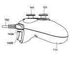
図1に、本願発明によるコントローラの本体100の平面図とカバー部材200の斜視図、図2にコントローラの本体100の底面図、図3に同左側面図、図4に右側面図、図5に正面図、図6に背面図をそれぞれ示す。
Hereinafter, preferred embodiments of the present invention will be described with reference to the drawings.
1 is a plan view of a
コントローラは、ゲームを実行することのできる所定の機器に対してデータの入力を行うためのものである。これには限られないが、この実施形態におけるコントローラは、ゲーム機に対して入力を行うためのものである。その意味では、このコントローラは、ゲーム機用のコントローラである。ゲーム機は、例えば、家庭用の据置型のゲーム専用機であり、例えば、株式会社ソニー・インタラクティブエンタテインメントが製造、販売を行うPlayStation 4(商標)、又は日本マイクロソフト株式会社が製造、販売を行うXbox One(商標)である。 The controller is for inputting data to a predetermined device capable of executing a game. Although not limited to this, the controller in this embodiment is for performing input to the game machine. In that sense, this controller is a controller for a game machine. The game machine is, for example, a stationary game-only game machine for home use. For example, PlayStation 4 (trademark) manufactured and sold by Sony Interactive Entertainment Inc. or Xbox manufactured and sold by Microsoft Japan Co., Ltd. One (trademark).
ゲーム専用機における純正コントローラのドミナントデザインは、背景技術で述べたように殆ど固まっており、このコントローラのデザインも、基本的にそれを踏襲している。
図1に示したように、この実施形態におけるコントローラは、それ自体でコントローラとして完成しており、ユーザがデータの入力を行うことのできる本体100と、本体100に対して後述するように2つの態様で着脱自在に固定することのできるカバー部材200とを備えて構成されている。
The dominant design of the genuine controller in the game console is almost solid as mentioned in the background art, and the design of this controller basically follows that.
As shown in FIG. 1, the controller in this embodiment is completed as a controller by itself, and has a
コントローラにおける本体100は、背景技術において説明したコントローラそのものに相当する。本体100は、両手で把持できるような横長形状のケース110を備えている。ケース110の両手前側には、ユーザがその両手で把持し易いように手前側に突出した把持部111が設けられている。ケース110は中空である。なお、ケース110も含め、ケース110から露出している部品は、これには限られないがこの実施形態ではすべて樹脂製の成形品である。
The
ケース110の上面の右側部分の下方には、スティックタイプの入力装置である第1スティック入力装置121が設けられている。第1スティック入力装置121はその下端で本体100に接続されており、その本体100との接続部分を支点として全方向にピボット運動を行えるようにされた入力装置である。ユーザは、第1スティック入力装置121をどの方向に倒すかにより、所望の入力を行うことができる。
ケース110の上面の右側部分の上方には、4つで上下左右で一組とされた押しボタン122A、122B、122C、122Dを備えた押しボタン式の第1押しボタン入力部122が設けられている。押しボタン122A、122B、122C、122Dはいずれも、ケース110に対して押し込むことが可能とされており、それらのうちの任意のものをケース110に対して押し込むことにより、各押しボタン122A、122B、122C、122Dにそれぞれ割振られたもっぱらゲームの操作に関する入力をユーザが行えるようになっている。なお、第1押しボタン入力部122は、はっきりとした境界はないが、4つの押しボタン122A、122B、122C、122D、及びそれらの幾らか外側をまとめて囲むケース110表面の所定の範囲を意味する。
ケース110の背面の右側部分には、上下に2つ並んだトリガーボタン123A、123Bが設けられている。トリガーボタン123A、123Bはケース110に対して手前側に押し込むことが可能とされており、それらのうちの任意のものをケース110に対して押し込むことにより、各トリガーボタン123A、123Bにそれぞれ割振られたもっぱらゲームの操作に関する入力をユーザが行えるようになっている。
なお、第1スティック入力装置121と、第1押しボタン入力部122における4つの押しボタン122A、122B、122C、122D、トリガーボタン123A、123Bはいずれも、公知又は周知のもので良く、この実施形態ではそうされている。
A first
Above the right side portion of the upper surface of the
Two right and
It should be noted that the first
ケース110の上面の幅方向の中央には、4つで上下左右で一組とされた押しボタン131A、131B、131C、131Dを備えた押しボタン式の第2押しボタン入力部131が設けられている。押しボタン131A、131B、131C、131Dは、押しボタン122A、122B、122C、122Dと同様に、ケース110に対して押し込むことが可能とされており、それらのうちの任意のものをケース110に対して押し込むことにより、各押しボタン131A、131B、131C、131Dにそれぞれ割振られた入力をユーザが行えるようになっている。もっともこれらの押しボタン131A、131B、131C、131Dに割振られた入力は、例えば、ゲームのポーズやゲーム機の電源の操作などに関するもっぱらゲームの操作に関係ないものとされる。なお、第2押しボタン入力部131は、はっきりとした境界はないが、4つの押しボタン131A、131B、131C、131D、及びそれらの幾らか外側をまとめて囲むケース110表面の所定の範囲を意味する。
なお、4つの押しボタン131A、131B、131C、131Dはいずれも、公知又は周知のもので良く、この実施形態ではそうされている。
In the center of the upper surface of the
Note that all four
ケース110の上面の左側部分の上方には、スティックタイプの入力装置である第2スティック入力装置141が設けられている。第2スティック入力装置141は、第1スティック入力装置121と同様に構成されており、ユーザはその操作により所望の入力を行うことができる。
ケース110の上面の右側部分の下方には、4つで上下左右で一組とされた押しボタン142A、142B、142C、142Dを備えた押しボタン式の第3押しボタン入力部142が設けられている。第1押しボタン入力部122、第2押しボタン入力部131、第3押しボタン入力部142のうち、第3押しボタン入力部142のみが本願発明における押しボタン入力部に相当する。押しボタン142A、142B、142C、142Dはいずれも、押しボタン122A、122B、122C、122Dと同様に、ケース110に対して押し込むことが可能とされており、それらのうちの任意のものをケース110に対して押し込むことにより、各押しボタン142A、142B、142C、142Dにそれぞれ割振られたもっぱらゲームの操作に関する入力をユーザが行えるようになっている。
ケース110の上側の面の表面であって、押しボタン142A、142B、142C、142Dを含む円形の範囲は、ケース110の表面から、円筒形状に一段(これには限られないが、この実施形態では6mm程度)凹んだ形状となっている。押しボタン142A、142B、142C、142Dは、その凹みの底の円形の平面上に設けられている。各押しボタン142A、142B、142C、142Dは平面視円形であり、その直径はすべて等しく、力を加えられていないときにおけるケース110からの突出量もすべて等しく、また、本体100を平面視した場合に所定の正方形の4つの頂点にそれらの中心が位置するようになっている。押しボタン142A、142B、142C、142Dを含むかかる断面円形の空間をこの実施形態における第3押しボタン入力部142と定義する。もっとも、第3押しボタン入力部142を平面視した場合の形状が、例えば、楕円形状や正方形を含む矩形等の他の形状であっても良いことは当然である。
第3押しボタン入力部142の底の中央には、この実施形態では、その断面が円形とされた穴である凹部142Eが設けられている。凹部142Eは有底であり、その第3押しボタン入力部142の円形の底からの深さは、これには限られないが、この実施形態では7mm程度とされている。
ケース110の背面の左側部分には、上下に2つ並んだトリガーボタン143A、143Bが設けられている。トリガーボタン143A、143Bは、トリガーボタン123A、123Bと同様に構成されており、その操作によりユーザはもっぱらゲームの操作に関する入力を行えるようになっている。
なお、第2スティック入力装置141と、第3押しボタン入力部142における4つの押しボタン142A、142B、142C、142D、トリガーボタン143A、143Bはいずれも、公知又は周知のもので良く、この実施形態ではそうされている。
A second
Below the right side portion of the upper surface of the
A circular area on the upper surface of the
In the center of the bottom of the third push
It should be noted that the second
ケース110の背面には、接続コード150が接続されている。なお、すべての図で接続コード150は、その途中で切断した状態で描かれている。接続コードは150、コントローラでなされた入力を図外のゲーム機に伝達するケーブルを内蔵したコードである。
もっとも、周知のようにコントローラでなされた入力をゲーム機に伝達するのは、接続コード150の如き有線で行う必要はなく、無線で入力の伝達を行う場合には接続コード150は省略可能である。
A
However, as is well known, it is not necessary to transmit the input made by the controller to the game machine by wire like the
ケース110の底面における幅方向の中央付近であって、その前後方向の中央付近には、収納部160が設けられている。ケース110における収納部160が存在する位置は、ユーザがコントローラを使用するにあたって本体100、或いはケース110を把持したときにおいて、ユーザの指が届かない位置である。
収納部160は、ケース110の底面の表面を円筒形に一段凹ませて形成されている。収納部160の直径は、第3押しボタン入力部142の底の円形の底面の部分の直径と略同じにされており、これには限られないがこの実施形態では事実上同じとされている。収納部160は有底であり、ケース110底面の表面からの深さは、これには限られないが、この実施形態では6mm程度とされている。
収納部160の底の中央には、この実施形態では、その断面が円形とされた穴である収納凹部161が設けられている。収納凹部161は有底であり、その収納部160の底からの深さは、これには限られないが、この実施形態では10mm程度とされている。収納凹部161の直径は、凹部142Eの直径と略同じにされており、これには限られないがこの実施形態では事実上同じとされている。
収納部160の底には、カバー部材200の裏面に設けられた後述する係止部の形状に対応した凹凸を有する受け部162が形成されている。
A
The
In the center of the bottom of the
On the bottom of the
次に、カバー部材200の構成について説明する。カバー部材200の平面図、側面図、底面図をそれぞれ、図7(A)、(B)、(C)に示す。
カバー部材200は全体として板状とされたカバー部210を備えている。カバー部210は、平面視円形とされた円板である円板部211を備えている。円板部211の直径は、円筒形の空間である第3押しボタン入力部142の断面の直径よりも幾らか小さくされている。円板部211の上側の面には円板部211の表面から十字形状に突出した十字キー部212を備えている。平面視した場合における十字キー部212の4本のアームの中心は、円板部211の中心に一致するようにされている。なお、円板部211の形状は、例えば、第3押しボタン入力部142の断面形状に合わせ、それよりも一回り小さくすることができる。
カバー部材200の裏面には、カバー固定部220が設けられている。カバー固定部220は、コントローラの本体100との着脱自在な固定をなすためのものである。
カバー固定部220は、円板部211の裏面の中心から円板部211に対して垂直に伸びる断面円形の柱部221を備えている。柱部221の先端の外側には、柱部221の先端からその基端に向けて曲折されたものであり、柱部221の中心方向への力を加えることにより柱部221に向かって近づき、その状態では元の状態に復帰する弾性力を生じるバネ部222を備えている。柱部221の直径は、凹部142Eの直径に略等しく、より正確には凹部142Eの直径よりも僅かに短くなっている。
また、カバー部材200の裏面には、カバー固定部220の一部である係止部223が設けられている。係止部223は、この実施形態では、柱部221を中心にして90°おきの対称な位置に4つ設けられている。係止部223は、外向きに開放された略Cの字型の壁である係止壁223Aと、係止壁223Aで囲まれた範囲に設けられたお椀型の凹みである凹面223Bとを備えている。
係止壁223Aは、ある円弧の一部を切り欠いたものであり、その円弧の内側面の直径は、第3押しボタン入力部142における4つの押しボタン142A、142B、142C、142Dの直径に等しい。係止壁223Aの円板部211の裏面からの突出量は、押しボタン142A、142B、142C、142Dのケース110からの突出量に略対応しており、例えば凡そ2mmである。凹面223Bは、押しボタン142A、142B、142C、142Dの上側の面に与えられたアールに略対応した曲面である。
Next, the configuration of the
The
A
The
Further, on the back surface of the
The locking
ケース110の内部には、第1スティック入力装置121、第1押しボタン入力部122における4つの押しボタン122A、122B、122C、122D、トリガーボタン123A、123B等を始めとする多数の入力装置からの入力に基いて信号を生成する機能、生成した信号を接続コード150を介してゲーム機に送信する機能等を有する、これも公知又は周知の図示を省略の回路基板が内蔵されている。
Inside the
以上で説明したコントローラの使用方法、及び動作について説明する。
もっとも、かかるコントローラの使用方法、及び動作は、第3押しボタン入力部142、収納部160、及びカバー部材200の使用方法、及び動作を除いて、一般的なコントローラの使用方法、及び動作と変わらない。一般的なコントローラの使用方法、及び動作と異なる部分を中心にそれらの説明する。
The usage and operation of the controller described above will be described.
However, the usage and operation of the controller are the same as the usage and operation of the general controller except for the usage and operation of the third push
ユーザは、コントローラを使用する場合、その第3押しボタン入力部142における押しボタン142A、142B、142C、142Dを、そのまま用いるか、つまりそのそれぞれを直接指で押し込むことにより入力するか、それとも後述するようにカバー部材200を介して間接的に押し込むことにより入力するか、を選択する。
When the user uses the controller, the
ユーザが、カバー部材200を介して押しボタン142A、142B、142C、142Dを入力することを選択した場合について説明する。
カバー部材200は、そのカバー部210の裏側にある柱部221を、第3押しボタン入力部142の中心にある穴である凹部142Eに挿入することにより、第3押しボタン入力部142に対して固定される。柱部221を凹部142に挿入すると、柱部221の先端にあるバネ部222が、凹部142Eの内周面から力を受け、柱部221に向けて縮められる。他方、バネ部222は、凹部142Eの内周面を押す。これによって生じる、バネ部222と凹部142Eの内周面との摩擦により、柱部221は凹部142Eに対して固定され、結果としてカバー部材200は第3押しボタン入力部142に対して固定されるのである。
より詳細に説明すると、カバー部材200を第3押しボタン入力部142に固定する際には、ユーザは、ある程度柱部221を凹部142Eに対して挿入した状態で、カバー部材200の全体を凹部142Eに挿入された柱部221を軸として適宜の角度左右に回転させる。そうすると、カバー部210の底面にある4つの係止部223における係止壁223Aがそれぞれ、押しボタン142A、142B、142C、142Dの外側に嵌まると同時に、4つの凹面223Bが押しボタン142A、142B、142C、142Dの上面を、それらの上面に沿いつつ覆う状態となる(図8、図9)。4つの係止部223における係止壁223Aがそれぞれ、押しボタン142A、142B、142C、142Dの外側に嵌まると同時に、4つの凹面223Bが押しボタン142A、142B、142C、142Dの上面を、それらの上面に沿いつつ覆う状態となる瞬間に、ユーザはカバー部材200から、クリック感を感じることになる。それにより、ユーザは、カバー部材200が正しい位置(柱部221周りの正しい角度)に位置決めされて、第3押しボタン入力部142に固定されたことを知ることができる。
この状態では、カバー部材200の柱部221は、ある程度の力をかけない限り凹部142Eから引き抜かれることはないし、また4つの係止壁223Aがそれぞれ、押しボタン142A、142B、142C、142Dの外側に嵌まっているので、柱部221を中心として回転することもない。
また、カバー部材200が正しい位置に位置決めされた状態では、カバー部210における十字キー部212の4つのアームの下にそれぞれ、押しボタン142A、142B、142C、142Dが位置することとなる。上述の正しい位置は、押しボタン142A、142B、142C、142Dが仮想の正方形の頂点に位置することに対応して、90°おきに4つ存在するが、その4つのいずれの位置(向き)でカバー部材200が第3押しボタン入力部142に固定されたとしても、十字キー部212の4つのアームの下にそれぞれ、押しボタン142A、142B、142C、142Dが位置することとなる。
上記のようにこの実施形態では、カバー部材200における柱部221は、第3押しボタン入力部142における凹部142Eに挿入され、カバー部材と第3押しボタン入力部142との固定が行われる。つまり、前者が後者に挿入されるような、前者が凸、後者が凹の関係となっているが、この関係は逆転していても構わない。柱部221と収納凹部161との関係においても同様である。
A case where the user selects to input the
The
More specifically, when fixing the
In this state, the
Further, when the
As described above, in this embodiment, the
この状態で、ユーザは、コントローラを操作する。
カバー部材200が第3押しボタン入力部142に固定された状態では、円板部211の下面の4つの凹面223Bが、押しボタン142A、142B、142C、142Dに触れるか触れないかの状態にある。
この状態でユーザは十字キー部212のいずれかのアームを押し込む。そうすると、カバー部210が柱部221に対して傾いて、そのアームの下にあるいずれかの、押しボタン142A、142B、142C、142Dが、円板部211の下面、或いは凹面223Bの下面に押されて押し込まれる。なお、カバー部210と柱部221との接続部分は、カバー部材200が樹脂の成形品あることもあり、上述の如きカバー部210の傾斜の発生を許容する程度の剛性となっている。そうすると、公知、周知のコントローラで行われるようにして、押し込まれた、押しボタン142A、142B、142C、142Dに対応した信号が生じ、それが接続コード150を介してゲーム機に出力される。
なお、かかるカバー部材200を用いてユーザが第3押しボタン入力部142に含まれる押しボタン142A、142B、142C、142Dに対する入力を行う場合には、仮想の正方形の対角にある押しボタン142Aと押しボタン142Cは同時に押し込まれることがなく、また押しボタン142Bと押しボタン142Dも同時に押し込まれることがない。そのようなことが防止される程度に、円板部211の剛性は高くされている。
もっとも、十字キー部212の隣接する2つのアームを同時に押し込む(その場合、円板部211は押された2つのアームの間に向けて下り傾斜を生じる状態となる。)ことにより、4つの押しボタン142A、142B、142C、142Dのうちの隣接する2つを同時に押し込むことは、カバー部材200が第3押しボタン入力部142に固定されていたとしても許容される。
In this state, the user operates the controller.
When the
In this state, the user pushes one of the arms of the cross
When the user uses the
However, by pushing two adjacent arms of the cross
ユーザが、コントローラを、その第3押しボタン入力部142における押しボタン142A、142B、142C、142Dを、そのまま用いる場合、カバー部材200を、本体100から外せば良い。
カバー部材200を本体100から外すには、バネ部222と凹部142Eの内周面との摩擦力に勝つ力で、カバー部材200を上方に引き上げ、ケース110の凹部142Eからカバー部材200における柱部221を引き抜けば良い。それにより、カバー部材200は本体100から取り外される。
カバー部材200は、そのままユーザにより管理されても良いが、そうするとカバー部材200が紛失するおそれがある。そこで、通常は、ユーザは、カバー部材200を、ケース110の底面の収納部160に固定して収納した状態とする(図10、11、12)。この状態を、ユーザがコントローラを使用しない場合におけるコントローラの状態とすることも可能であり、また、カバー部材200と本体100とをセット売りする場合のデフォルトの状態とすることも可能である。
本体100の収納部160にカバー部材200を固定して収納するには、ユーザは、カバー部材200のカバー固定部220における柱部221を、カバー部材200を第3押しボタン入力部142に対して着脱自在に固定する場合と同様にして、収納凹部161に対して固定させる。バネ部222が収納凹部161の内周面との間で生じる摩擦力によって柱部221が収納凹部161に固定され、ひいてはカバー部材200が収納部160に対して固定されることは、カバー部材200を第3押しボタン入力部142に対して固定する場合と同様である。また、カバー部材200を収納凹部161に固定する場合には、カバー部材200を第3押しボタン入力部142に対して固定する場合と同様に、柱部221を収納凹部161にある程度押し込んだ状態で、柱部221を軸として収納凹部161を回転させる。そうすると、カバー部材200の下の係止壁223Aと凹面223Bとが、収納凹部161の底にある受け部162にしっかりと嵌まる。そのときユーザはクリック感を感じるから、収納凹部161にカバー部材200がしっかりと嵌ったことを知ることができる。受け部162は、簡単に言うと、第3押しボタン入力部142の底面の形状を模したものであり、より詳細には、4つの押しボタン142A、142B、142C、142Dの第3押しボタン入力部142の底面から露出している部分の形状を模した4つの凸部を有する。かかる4つの凸部がカバー部材200の下の係止壁223Aに囲まれた状態となり、且つ凹面223Bと当接した状態となることにより、収納凹部161に固定されたカバー部材200は、90°おきの4つの角度のいずれかの向きに必ず固定されることになる。
なお、収納凹部161は収納という言葉を用いているが、収納凹部161にカバー部材200が固定された場合において、カバー部材200の一部、例えば、十字キー部212は、収納凹部161から一部覗いても構わない(図11、図12)。
この状態でユーザは、4つの押しボタン142A、142B、142C、142Dのうちの任意のものを直接、それこそ普通のコントローラの押しボタンを押すのと同様に押すことにより、各押しボタン142A、142B、142C、142Dに割振られた信号を発生させることができる。このとき収納凹部161及びそこに固定され収納されたカバー部材200は、コントローラを用いて入力を行うユーザの指とは当接しない。発生した信号は当然の如くに、接続コード150を介してゲーム機に送られる。
収納凹部161からカバー部材200を取り外す方法は、第3押しボタン入力部142からカバー部材200を取り外す方法に倣う。
When the user uses the
In order to remove the
The
To fix and store the
Although the word “storage” is used for the
In this state, the user presses any one of the four
The method of removing the
なお、カバー部材200をユーザに対して提供するものは、上述のカバー部材200と素材や色彩の異なる、或いは多少の寸法違いの複数種類のカバー部材200をユーザに提供することも可能である。それによれば、ユーザは好みのカバー部材200を選択することになり、ユーザの満足度が高まることが期待できる。
It should be noted that what provides the
100 本体
110 ケース
142 第3押しボタン入力部
142A 押しボタン
142B 押しボタン
142C 押しボタン
142D 押しボタン
142E 凹部
160 収納部
161 収納凹部
162 受け部
200 カバー部材
210 カバー部
211 円板部
212 十字キー部
220 カバー固定部
221 柱部
222 バネ部
223 係止部
223A 係止壁
223B 凹面
100
Claims (8)
前記押しボタン入力部に対して着脱自在な固定を行えるようにされたカバー固定部と、前記カバー固定部が前記本体に対して固定されたときに前記押しボタン入力部における4つの前記押しボタンのすべてを少なくとも覆う、一体物とされ且つ板状とされたカバー部と、を備えた樹脂製の一体成形品であるカバー部材を備えており、
前記カバー固定部が前記押しボタン入力部に対して固定された状態で、前記カバー部の所定の位置を押し込むことにより、4つの前記押しボタンによる入力を行えるようになっており、
前記カバー部材は、前記カバー部の裏側に前記カバー固定部を備えているとともに、前記押しボタン入力部は、前記カバー固定部と係合することにより、前記カバー固定部と着脱自在な固定をなすことができるコントローラ固定部を備えており、
且つ、前記カバー固定部と、前記コントローラ固定部とは、その一方が凸部でその他方が凹部とされており、前記凹部に前記凸部を挿入することで両者が係合し、それにより両者が着脱自在な固定をなすことができるようになっている、
コントローラ。 A controller provided with a push-button input section, which is arranged at each of the positions of the vertices of a square and has a set of four push buttons for inputting by pushing, in a main body held by a user,
A cover fixing portion adapted to be detachably fixed to the push button input portion, and four push buttons in the push button input portion when the cover fixing portion is fixed to the main body. A cover member that is a resin integrally- molded product that includes at least an all-in-one and plate-shaped cover portion that covers all of the above,
With the cover fixing portion fixed to the push button input portion, by pushing a predetermined position of the cover portion, it is possible to perform input by the four push buttons.
The cover member includes the cover fixing portion on the back side of the cover portion, and the push button input portion is detachably fixed to the cover fixing portion by engaging with the cover fixing portion. It has a controller fixing part that can
In addition, one of the cover fixing portion and the controller fixing portion is a convex portion and the other is a concave portion, and the two are engaged by inserting the convex portion into the concave portion, whereby both Can be detachably fixed,
controller.
請求項1記載のコントローラ。 On the front surface of the cover portion, touch the front surface of the cover portion with the positions of the four push buttons under the cover portion when the cover fixing portion is fixed to the push button input portion. Concavity and convexity that the user can recognize by touch,
The controller according to claim 1.
請求項2記載のコントローラ。 When the cover fixing portion is positioned such that the direction of the unevenness in the cover portion is one of four directions at 90° intervals corresponding to the positions of the four push buttons, the push button input is performed. It is designed so that it can be detachably fixed to the section.
The controller according to claim 2.
請求項2記載のコントローラ。 The unevenness has a cross shape, and when the cover fixing portion is fixed to the push button input portion, the four push buttons are respectively located under the four arms of the cross.
The controller according to claim 2.
請求項3記載のコントローラ。 The cover fixing portion is locked to at least one of the four push buttons so that the direction of the unevenness in the cover portion can be changed in four directions at 90° intervals corresponding to the positions of the four push buttons. It is designed to be positioned so that either
The controller according to claim 3.
請求項1記載のコントローラ。 The cover member is a disk having its center of gravity as the center of gravity of the square on which the four push buttons ride.
The controller according to claim 1.
請求項1記載のコントローラ。 The cover member is attached/detached to/from a portion of the main body that does not interfere with a user's finger when the user holds the controller by a normal method when the cover fixing portion is released from the push button input portion. It can be fixed freely,
The controller according to claim 1.
前記コントローラ固定部に対して着脱自在な固定を行えるようにされたカバー固定部と、
前記カバー固定部が前記コントローラ固定部に対して固定されたときに前記押しボタン入力部における4つの前記押しボタンのすべてを少なくとも覆う、一体物とされ且つ板状とされたカバー部と、
を備えており、
前記カバー固定部が前記押しボタン入力部に対して固定された状態で、前記カバー部の所定の位置を押し込むことにより、4つの前記押しボタンによる入力を行えるようになっており、
前記カバー固定部は前記カバー部の裏側に設けられているとともに、前記押しボタン入力部には、前記カバー固定部と係合することにより、前記カバー固定部と着脱自在な固定をなすことができるコントローラ固定部が設けられており、
且つ、前記カバー固定部と、前記コントローラ固定部とは、その一方が凸部でその他方が凹部とされており、前記凹部に前記凸部を挿入することで両者が係合し、それにより両者が着脱自在な固定をなすことができるようになっている、
カバー部材。 The push button input section, which has four sets of push buttons, each of which is arranged at the position of the apex of the square and which performs input by pushing, is provided in the main body held by the user, and the push button input section is provided with A cover member which is a resin integrally molded product used in combination with a controller provided with a controller fixing portion,
A cover fixing portion adapted to be detachably fixed to the controller fixing portion,
A cover part which is an integral and plate-like cover for covering at least all of the four push buttons in the push button input part when the cover fixing part is fixed to the controller fixing part;
Is equipped with
With the cover fixing portion fixed to the push button input portion, by pushing a predetermined position of the cover portion, it is possible to perform input by the four push buttons.
The cover fixing portion is provided on the back side of the cover portion, and the push button input portion can be detachably fixed to the cover fixing portion by engaging with the cover fixing portion. A controller fixing part is provided,
In addition, one of the cover fixing portion and the controller fixing portion is a convex portion and the other is a concave portion, and the two are engaged by inserting the convex portion into the concave portion, whereby both Can be detachably fixed,
Cover member.
Priority Applications (5)
| Application Number | Priority Date | Filing Date | Title |
|---|---|---|---|
| JP2016239434A JP6730918B2 (en) | 2016-12-09 | 2016-12-09 | Controller, cover member |
| PCT/JP2017/043475 WO2018105556A1 (en) | 2016-12-09 | 2017-12-04 | Controller and cover member |
| US16/337,374 US11033811B2 (en) | 2016-12-09 | 2017-12-04 | Controller and cover member |
| EP17877855.1A EP3552677A4 (en) | 2016-12-09 | 2017-12-04 | Controller and cover member |
| CN201780052665.9A CN109641151A (en) | 2016-12-09 | 2017-12-04 | Controller, cover member |
Applications Claiming Priority (1)
| Application Number | Priority Date | Filing Date | Title |
|---|---|---|---|
| JP2016239434A JP6730918B2 (en) | 2016-12-09 | 2016-12-09 | Controller, cover member |
Publications (2)
| Publication Number | Publication Date |
|---|---|
| JP2018093969A JP2018093969A (en) | 2018-06-21 |
| JP6730918B2 true JP6730918B2 (en) | 2020-07-29 |
Family
ID=62491532
Family Applications (1)
| Application Number | Title | Priority Date | Filing Date |
|---|---|---|---|
| JP2016239434A Expired - Fee Related JP6730918B2 (en) | 2016-12-09 | 2016-12-09 | Controller, cover member |
Country Status (5)
| Country | Link |
|---|---|
| US (1) | US11033811B2 (en) |
| EP (1) | EP3552677A4 (en) |
| JP (1) | JP6730918B2 (en) |
| CN (1) | CN109641151A (en) |
| WO (1) | WO2018105556A1 (en) |
Families Citing this family (2)
| Publication number | Priority date | Publication date | Assignee | Title |
|---|---|---|---|---|
| TWM569644U (en) * | 2018-07-30 | 2018-11-11 | 正崴精密工業股份有限公司 | Game controller |
| JP7140720B2 (en) * | 2019-07-05 | 2022-09-21 | 東洋電装株式会社 | lever switch |
Family Cites Families (21)
| Publication number | Priority date | Publication date | Assignee | Title |
|---|---|---|---|---|
| US4786768A (en) * | 1987-08-20 | 1988-11-22 | Interlock | Manual cursor actuator for electronic keyboards |
| US4825019A (en) * | 1988-04-14 | 1989-04-25 | Fisher David H | Cursor control accessory for a computer keyboard |
| US5034574A (en) * | 1988-04-18 | 1991-07-23 | Martovitz Thomas J | Joystick for computer keyboards |
| US4945357A (en) * | 1988-08-29 | 1990-07-31 | Rotal Industries & Trading Ltd. | Joystick assembly |
| JP2540505Y2 (en) * | 1991-03-25 | 1997-07-09 | 日本電気ホームエレクトロニクス株式会社 | Input device for electronic equipment |
| US5476261A (en) * | 1992-05-07 | 1995-12-19 | Hultstrand; Victor S. | Adaptor for a machine having a controller and buttons for operation thereof |
| US5343219A (en) * | 1992-11-23 | 1994-08-30 | Dubosque Jr Clayton | Cursor key actuating assembly |
| JPH0733394U (en) * | 1993-12-02 | 1995-06-20 | 株式会社セガ・エンタープライゼス | Video game console controller |
| JP3628358B2 (en) * | 1994-05-09 | 2005-03-09 | 株式会社ソニー・コンピュータエンタテインメント | Game console controller |
| JP2907008B2 (en) * | 1994-07-05 | 1999-06-21 | 株式会社セガ・エンタープライゼス | Control pad with multiple controls |
| JP3165853B2 (en) * | 1996-03-29 | 2001-05-14 | 株式会社セガ | Cross key adapter device and controller |
| JPH09262336A (en) * | 1996-03-29 | 1997-10-07 | Ace Denken:Kk | Slot machine |
| US5976018A (en) * | 1997-02-05 | 1999-11-02 | Tiger Electronics, Ltd. | Joystick adapter |
| US5883690A (en) * | 1997-05-30 | 1999-03-16 | Z-Products | Joystick adapter for a directional keypad on a game controller |
| JPH1153994A (en) * | 1997-07-31 | 1999-02-26 | Sega Enterp Ltd | Operation device and grip for the same |
| JP3066234U (en) * | 1999-07-30 | 2000-02-18 | ホリ電機株式会社 | Cross key switch mechanism for adjusting operation feeling in game machine controller |
| US6811491B1 (en) * | 1999-10-08 | 2004-11-02 | Gary Levenberg | Interactive video game controller adapter |
| US8941594B2 (en) * | 2004-10-01 | 2015-01-27 | Nvidia Corporation | Interface, circuit and method for interfacing with an electronic device |
| JP5290844B2 (en) * | 2009-04-13 | 2013-09-18 | 株式会社ソニー・コンピュータエンタテインメント | Operation device and portable terminal |
| JP6155580B2 (en) * | 2012-09-11 | 2017-07-05 | オムロン株式会社 | Operation switch |
| US10124249B2 (en) | 2015-05-01 | 2018-11-13 | Microsoft Technology Licensing, Llc | Game controller with removable controller accessory |
-
2016
- 2016-12-09 JP JP2016239434A patent/JP6730918B2/en not_active Expired - Fee Related
-
2017
- 2017-12-04 EP EP17877855.1A patent/EP3552677A4/en not_active Withdrawn
- 2017-12-04 US US16/337,374 patent/US11033811B2/en active Active
- 2017-12-04 WO PCT/JP2017/043475 patent/WO2018105556A1/en unknown
- 2017-12-04 CN CN201780052665.9A patent/CN109641151A/en active Pending
Also Published As
| Publication number | Publication date |
|---|---|
| EP3552677A1 (en) | 2019-10-16 |
| EP3552677A4 (en) | 2020-08-05 |
| JP2018093969A (en) | 2018-06-21 |
| US11033811B2 (en) | 2021-06-15 |
| CN109641151A (en) | 2019-04-16 |
| US20200030694A1 (en) | 2020-01-30 |
| WO2018105556A1 (en) | 2018-06-14 |
Similar Documents
| Publication | Publication Date | Title |
|---|---|---|
| EP2900344B1 (en) | A game controller | |
| US10773155B2 (en) | Game machine controller | |
| JP4277140B2 (en) | Electronic device and game controller | |
| US8188977B2 (en) | Operation input device and character input device | |
| JP5161338B2 (en) | keyboard | |
| JPH1190042A (en) | Controller for game machine | |
| WO1998016285A1 (en) | Operating device for game machines | |
| US20140083833A1 (en) | Miniaturized joystick assembly | |
| JPH10295937A (en) | Operation device for game machine | |
| CN110740794A (en) | Input device for game host | |
| JP2006086099A (en) | Button structure and portable electronic equipment | |
| EP3254734B1 (en) | Game controller | |
| JP2017221631A (en) | Game controller | |
| JP2023182626A (en) | Input device, game controller, and information processing apparatus | |
| JP6730918B2 (en) | Controller, cover member | |
| WO2017216978A1 (en) | Dedicated game device controller and dedicated game device controller system | |
| KR102284462B1 (en) | A game controller on mobile touch-enabled devices | |
| CN210109752U (en) | Single-hand game keyboard | |
| JPH0975544A (en) | Controller for game machine | |
| KR20090120329A (en) | Joystick assembly | |
| KR200429744Y1 (en) | Joystick | |
| US20230090962A1 (en) | Hand-held controller | |
| JP3208523U (en) | Game console control keys | |
| JP7431350B2 (en) | Input devices, game controllers, information processing devices | |
| TW201310484A (en) | Keyboard for playing computer games |
Legal Events
| Date | Code | Title | Description |
|---|---|---|---|
| A621 | Written request for application examination |
Free format text: JAPANESE INTERMEDIATE CODE: A621 Effective date: 20190207 |
|
| A131 | Notification of reasons for refusal |
Free format text: JAPANESE INTERMEDIATE CODE: A131 Effective date: 20200128 |
|
| A521 | Request for written amendment filed |
Free format text: JAPANESE INTERMEDIATE CODE: A523 Effective date: 20200313 |
|
| A131 | Notification of reasons for refusal |
Free format text: JAPANESE INTERMEDIATE CODE: A131 Effective date: 20200421 |
|
| A521 | Request for written amendment filed |
Free format text: JAPANESE INTERMEDIATE CODE: A523 Effective date: 20200609 |
|
| TRDD | Decision of grant or rejection written | ||
| A01 | Written decision to grant a patent or to grant a registration (utility model) |
Free format text: JAPANESE INTERMEDIATE CODE: A01 Effective date: 20200623 |
|
| A61 | First payment of annual fees (during grant procedure) |
Free format text: JAPANESE INTERMEDIATE CODE: A61 Effective date: 20200703 |
|
| R150 | Certificate of patent or registration of utility model |
Ref document number: 6730918 Country of ref document: JP Free format text: JAPANESE INTERMEDIATE CODE: R150 |
|
| LAPS | Cancellation because of no payment of annual fees |