CN112438003A - Heat sink for high-voltage switchgear - Google Patents
Heat sink for high-voltage switchgear Download PDFInfo
- Publication number
- CN112438003A CN112438003A CN201980046544.2A CN201980046544A CN112438003A CN 112438003 A CN112438003 A CN 112438003A CN 201980046544 A CN201980046544 A CN 201980046544A CN 112438003 A CN112438003 A CN 112438003A
- Authority
- CN
- China
- Prior art keywords
- heat sink
- air channel
- central axis
- radius
- sink according
- Prior art date
- Legal status (The legal status is an assumption and is not a legal conclusion. Google has not performed a legal analysis and makes no representation as to the accuracy of the status listed.)
- Pending
Links
Images


Classifications
-
- H—ELECTRICITY
- H01—ELECTRIC ELEMENTS
- H01H—ELECTRIC SWITCHES; RELAYS; SELECTORS; EMERGENCY PROTECTIVE DEVICES
- H01H9/00—Details of switching devices, not covered by groups H01H1/00 - H01H7/00
- H01H9/52—Cooling of switch parts
-
- H—ELECTRICITY
- H01—ELECTRIC ELEMENTS
- H01H—ELECTRIC SWITCHES; RELAYS; SELECTORS; EMERGENCY PROTECTIVE DEVICES
- H01H33/00—High-tension or heavy-current switches with arc-extinguishing or arc-preventing means
- H01H33/02—Details
-
- H—ELECTRICITY
- H02—GENERATION; CONVERSION OR DISTRIBUTION OF ELECTRIC POWER
- H02B—BOARDS, SUBSTATIONS OR SWITCHING ARRANGEMENTS FOR THE SUPPLY OR DISTRIBUTION OF ELECTRIC POWER
- H02B1/00—Frameworks, boards, panels, desks, casings; Details of substations or switching arrangements
- H02B1/56—Cooling; Ventilation
-
- H—ELECTRICITY
- H02—GENERATION; CONVERSION OR DISTRIBUTION OF ELECTRIC POWER
- H02G—INSTALLATION OF ELECTRIC CABLES OR LINES, OR OF COMBINED OPTICAL AND ELECTRIC CABLES OR LINES
- H02G5/00—Installations of bus-bars
- H02G5/10—Cooling
-
- H—ELECTRICITY
- H01—ELECTRIC ELEMENTS
- H01H—ELECTRIC SWITCHES; RELAYS; SELECTORS; EMERGENCY PROTECTIVE DEVICES
- H01H9/00—Details of switching devices, not covered by groups H01H1/00 - H01H7/00
- H01H9/52—Cooling of switch parts
- H01H2009/526—Cooling of switch parts of the high voltage switches
-
- H—ELECTRICITY
- H05—ELECTRIC TECHNIQUES NOT OTHERWISE PROVIDED FOR
- H05K—PRINTED CIRCUITS; CASINGS OR CONSTRUCTIONAL DETAILS OF ELECTRIC APPARATUS; MANUFACTURE OF ASSEMBLAGES OF ELECTRICAL COMPONENTS
- H05K7/00—Constructional details common to different types of electric apparatus
- H05K7/20—Modifications to facilitate cooling, ventilating, or heating
- H05K7/20009—Modifications to facilitate cooling, ventilating, or heating using a gaseous coolant in electronic enclosures
- H05K7/20136—Forced ventilation, e.g. by fans
- H05K7/20154—Heat dissipaters coupled to components
- H05K7/20163—Heat dissipaters coupled to components the components being isolated from air flow, e.g. hollow heat sinks, wind tunnels or funnels
Landscapes
- Engineering & Computer Science (AREA)
- Power Engineering (AREA)
- Cooling Or The Like Of Electrical Apparatus (AREA)
- Cooling Or The Like Of Semiconductors Or Solid State Devices (AREA)
- Patch Boards (AREA)
Abstract
The invention relates to a heat sink (10) for a high-voltage switchgear. The heat sink includes a body (20). The body is centered about a central axis extending in an axial direction from the first outer surface (30) to the second outer surface (40). At least one third outer surface (50) of the body extends from the first outer surface to the second outer surface. At least one air passage (60) extends through the body from the first outer surface to the second outer surface. The at least one air channel is surrounded by the at least one third outer surface.
Description
Technical Field
The present invention relates to a heat sink for a high voltage switchgear and to a medium or high voltage switchgear.
Background
Medium and/or high voltage components (e.g. medium or high voltage switchgears) need to be cooled using an external heat sink made of electrically conductive material. The heat sink is mounted on the component to be cooled, with fins outside the body of the heat sink, the fins having rounded edges to reduce electrical stress at these edges. The fins are typically quite thin and therefore these edges have a smaller radius. At small radii, electric field enhancement occurs, which reduces the dielectric properties. To alleviate this, an insulating layer is often applied to the stressed area of the heat spreader in order to avoid electrical discharges. Such a layer having a higher discharge voltage than the gas insulation material surrounding the arrangement serves to improve the dielectric properties. However, the discharge voltage of this configuration is reduced due to the electric field enhancement at the small radius point of the heat sink. Even with solid insulation on these radii, the weak points are the radii or rather the regions with solid insulation ends.
Therefore, there is a need for an improved heat sink for use in such situations.
Disclosure of Invention
It would therefore be advantageous to have an improved technique for providing a heat sink for medium or high voltage switchgear.
The object of the invention is solved by the subject matter of the independent claims, wherein further embodiments are incorporated in the dependent claims. It should be noted that the following described aspects of the invention also apply to the heat sink and the switchgear having at least one heat sink.
In a first aspect, a heat sink for a high voltage switchgear is provided, the heat sink comprising a body. The body is centered about a central axis that extends in an axial direction from a first outer surface of the body to a second outer surface of the body. At least one third outer surface of the body extends from the first outer surface to the second outer surface. At least one air passage extends through the body from the first outer surface to the second outer surface. The at least one air channel is surrounded by the at least one third outer surface.
In this way, the heat sink is not only cooled by radiative cooling from the outer surface, but also provides higher cooling by convective heat dissipation through the internal components of the heat sink. This enables an increased cooling capacity for removing heat from critical locations, such as pole parts, and for example connections and contacts within the switchgear. Therefore, the increase in contact resistance due to the generated heat is mitigated via effective heat dissipation from the new heat dissipation design having internal cooling capability.
Thus, medium or high voltage components such as switchgear may be cooled by an external heat sink. In an example, the heat sink is made of an electrically conductive material.
In an example, the at least one air channel comprises a ribbed surface.
In other words, the heat sink has internal ribs to provide higher convective cooling efficiency from the inside of the heat sink.
In an example, the ribbed surface extends from the first outer surface to the second outer surface.
In an example, the ribbed surface comprises fins extending in an axial direction.
In an example, the at least one air passage includes an air passage extending downward along a central axis of the body.
In an example, the at least one air channel includes at least one arcuate air channel.
In an example, the at least one arcuate air passage has a radius of curvature centered along the central axis.
In an example, the at least one arcuate air channel includes a plurality of air channels. Each air passage of the plurality of air passages has a different radius of curvature centered along the central axis.
In this way, the manufacturing of the heat sink is facilitated and a higher cooling capacity is provided.
In an example, at least a portion of the junction between the at least one third outer surface and the first outer surface has a convex rounded portion.
In an example, at least a portion of the junction between the at least one third outer surface and the second outer surface has a convex rounded portion.
In this way, the heat sink may have a smooth outer geometry with rounded edges at the surface with the large radius. This smooth surface reduces the electric field strength at the surface of the heat sink and thus improves the dielectric properties. This is helpful because the surface(s) of the heat sink for dissipating heat are located inside the heat sink, which is open to the surface, thereby facilitating convective cooling, but the internal cooling channels shield the electric field by the outer contour of the heat sink (which may be cylindrical, for example).
In an example, the at least one third outer surface includes a flat portion. The flat portion is configured to be mounted to one or more components of the high voltage switchgear.
Thus, the heat sink can easily be mounted at a suitable point (such as a pole part, and all connections and contacts) in a system (such as a switchgear).
In an example, the at least one third outer surface has a substantially cylindrical shape with a radius of curvature centered along the central axis.
In an example, the radius of curvature of the substantially cylindrical shape is selected such that in operation the electric field strength at the at least one third outer surface is minimized.
In an example, the body is made of aluminum.
In an example, the body is made by hollow extrusion.
In an example, the at least one third outer surface comprises a ribbed surface.
In a second aspect, a medium or high voltage switchgear is provided, comprising at least one heat sink according to the first aspect.
The aspects and examples described above will become apparent from and elucidated with reference to the embodiments described hereinafter.
Drawings
Exemplary embodiments will be described hereinafter with reference to the following drawings:
figure 1 shows a schematic representation of an example of a heat sink;
fig. 2 shows a detailed example of a heat sink; and
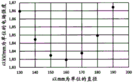
fig. 3 shows the electric field strength at the cylindrical surface of the heat sink of fig. 2.
Detailed Description
Fig. 1 shows an example of a heat sink 10 for a high voltage switchgear, wherein optional features are shown in dashed lines. The heat sink 10 includes a body 20. The body is centered about a central axis extending in an axial direction from the first outer surface 30 of the body to the second outer surface 40 of the body. At least one third outer surface 50 of the body extends from the first outer surface to the second outer surface. At least one air passage 60 extends through the body from the first outer surface to the second outer surface. The at least one air channel is surrounded by the at least one third outer surface.
According to an example, the at least one air channel comprises a ribbed surface.
According to an example, the ribbed surface extends from the first outer surface to the second outer surface.
According to an example, the ribbed surface comprises fins extending in an axial direction.
According to an example, the at least one air passage comprises an air passage extending downwardly along a central axis of the body.
According to an example, the at least one air channel comprises at least one curved air channel.
According to an example, the at least one arcuate air passage has a radius of curvature centered along the central axis.
According to an example, the at least one arcuate air channel includes a plurality of air channels, wherein each air channel of the plurality of air channels has a different radius of curvature centered along the central axis.
According to an example, at least a portion of the junction 70 between the at least one third outer surface and the first outer surface has a convex rounded portion.
According to an example, at least a portion of the junction 80 between the at least one third outer surface and the second outer surface has a convex rounded portion.
In an example, the rounded portion has a large radius of curvature. In an example, the radius of curvature is greater than a dimension of the body.
According to an example, the at least one third outer surface comprises a flat portion 90. The flat portion is configured to be mounted to one or more components of the high voltage switching device.
In an example, the body at the location of the flat portion has at least one threaded hole extending into the interior of the body. In an example, the at least one threaded hole has at least one central axis perpendicular to the flat portion.
According to an example, the at least one third outer surface has a substantially cylindrical shape with a radius of curvature centered along the central axis.
According to an example, the radius of curvature of the substantially cylindrical shape is selected such that in operation the electric field strength at the at least one third outer surface is minimized.
According to an example, the body is made of aluminum.
According to an example, the body is made by hollow extrusion.
According to an example, the at least one third outer surface comprises a ribbed surface.
In an example, the ribbed surface comprises fins extending in an axial direction.
The above references to air passages relate to passages through which air may be permitted to flow, but in some cases, gases other than air may be used in the apparatus, and the skilled person will appreciate that the passages are suitable for use in convective cooling flows associated with such other gases other than air.
One or more of the heat sinks described with respect to fig. 1 may be used to cool appropriate components of a medium or high voltage switchgear.
The heat sink of fig. 1 is described in more detail with reference to fig. 2 to 3.
Figure 2 shows in detail a heat sink with internal fins or ridges or ribs. The heat sink is made of aluminum, which has a cylindrical outer shape with rounded edges connecting the cylindrical portion to two planes. The rounded edges have a larger radius that reduces field enhancement at the outer surface of the heat sink compared to other heat sinks having features such as fins with small radii on the outer surface of the heat sink. Thus, the dielectric properties of the heat sink can be improved. Furthermore, when the distance from the center of the heat sink to the ground portion of the switchgear is fixed, the diameter of the heat sink may be selected for a particular implementation such that the electric field at the outer surface of the heat sink reaches a minimum. This is shown in fig. 3, which fig. 3 plots the electric field strength at a cylindrical surface with an applied voltage of 170kV and a fixed distance of 225mm between the central axis of the heat sink and the grounded wall.
With continued reference to fig. 2, fins for heat dissipation are located inside the cylindrical heat sink to provide sufficient surface for heat dissipation without requiring a small radius at the outer contour of the heat sink where electrical stress is highest. In the new design, heat is dissipated due to thermal convection of the gas along the inner fins, wherein due to the radiation emission from the outer surface and the airflow over the outer surface, radiation cooling and convection cooling are also provided. However, cooling is enhanced by providing internal fins, while improving dielectric properties. The inner fins also partially shield the electric field and therefore do not lead to a strong enhancement of the electric field. Furthermore, the geometry of the heat sink lends itself to fabrication by hollow extrusion, thereby providing inexpensive production. In this way, the cost per heat sink can be reduced compared to a conventional heat sink made of, for example, aluminum by die casting.
It should be noted that embodiments of the present invention are described with reference to different subject matters. In particular, some embodiments are described with reference to method type claims whereas other embodiments are described with reference to device type claims. However, a person skilled in the art will gather from the above and the following description that, unless other notified, in addition to any combination of features belonging to one type of subject-matter also any combination between features relating to different subject-matters is considered to be disclosed with this application. However, all features may be combined to provide a synergistic effect rather than merely a simple sum of the features.
While the invention has been illustrated and described in detail in the drawings and foregoing description, such illustration and description are to be considered illustrative or exemplary and not restrictive. The invention is not limited to the disclosed embodiments. Other variations to the disclosed embodiments can be understood and effected by those skilled in the art in practicing the claimed invention, from a study of the drawings, the disclosure, and the appended claims.
In the claims, the word "comprising" does not exclude other elements or steps, and the indefinite article "a" or "an" does not exclude a plurality. A single processor or other unit may fulfill the functions of several items recited in the claims. The mere fact that certain measures are recited in mutually different dependent claims does not indicate that a combination of these measures cannot be used to advantage. Any reference signs in the claims shall not be construed as limiting the scope.
Fig. 3 shows the electric field strength at the cylindrical surface with a fixed distance of 225mm between the center point of the heat sink and the grounded wall and an applied voltage of 170 kV. This calculation is done by the utilization factor of Schwaiger.
Claims (17)
1. A heat sink (10) for a high voltage switchgear, the heat sink comprising:
a body (20);
wherein the body is centered about a central axis extending in an axial direction from a first outer surface (30) of the body to a second outer surface (40) of the body;
wherein at least one third outer surface (50) of the body extends from the first outer surface to the second outer surface; and
wherein at least one air channel (60) extends through the body from the first outer surface to the second outer surface, and wherein the at least one air channel is surrounded by the at least one third outer surface.
2. The heat sink of claim 1, wherein the at least one air channel comprises a ribbed surface.
3. The heat sink of claim 2, wherein the ribbed surface extends from the first outer surface to the second outer surface.
4. A heat sink according to any one of claims 2 to 3, wherein the ribbed surface comprises fins extending in the axial direction.
5. The heat sink as recited in any one of claims 1 to 4 wherein the at least one air channel comprises an air channel extending downwardly along the central axis of the body.
6. The heat sink of any one of claims 1 to 5, wherein the at least one air channel comprises at least one arcuate air channel.
7. The heat sink of claim 6, wherein the at least one arcuate air channel has a radius of curvature centered along the central axis.
8. The heat sink of claim 7, wherein the at least one arcuate air channel comprises a plurality of air channels, wherein each air channel of the plurality of air channels has a different radius of curvature centered along the central axis.
9. The heat sink according to any one of claims 1-8, wherein at least a part of the junction (70) between the at least one third outer surface and the first outer surface has a convex rounded portion.
10. The heat sink according to any one of claims 1 to 9, wherein at least a part of a junction (80) between the at least one third outer surface and the second outer surface has a convex rounded portion.
11. The heat sink according to any one of claims 1 to 10, wherein the at least one third outer surface comprises a flat portion (90), wherein the flat portion is configured to be mounted to one or more components of a high voltage switching device.
12. The heat sink according to any one of claims 1 to 11, wherein the at least one third outer surface has a substantially cylindrical shape with a radius of curvature centered along the central axis.
13. The heat sink according to claim 12, wherein the radius of curvature of the substantially cylindrical shape is selected such that in operation the electric field strength at the at least one third outer surface is minimized.
14. The heat sink according to any one of claims 1 to 13, wherein the body is made of aluminum.
15. The heat sink according to any one of claims 1 to 14, wherein the body is made by hollow extrusion.
16. The heat sink of claim 15, wherein the at least one third outer surface comprises a ribbed surface.
17. Medium or high voltage switchgear comprising at least one heat sink according to any of claims 1 to 16.
Applications Claiming Priority (3)
| Application Number | Priority Date | Filing Date | Title |
|---|---|---|---|
| EP18183520.8 | 2018-07-13 | ||
| EP18183520.8A EP3595105B1 (en) | 2018-07-13 | 2018-07-13 | A heat sink for a high voltage switchgear |
| PCT/EP2019/068577 WO2020011872A1 (en) | 2018-07-13 | 2019-07-10 | A heat sink for a high voltage switchgear |
Publications (1)
| Publication Number | Publication Date |
|---|---|
| CN112438003A true CN112438003A (en) | 2021-03-02 |
Family
ID=63012807
Family Applications (1)
| Application Number | Title | Priority Date | Filing Date |
|---|---|---|---|
| CN201980046544.2A Pending CN112438003A (en) | 2018-07-13 | 2019-07-10 | Heat sink for high-voltage switchgear |
Country Status (5)
| Country | Link |
|---|---|
| US (1) | US11521807B2 (en) |
| EP (1) | EP3595105B1 (en) |
| CN (1) | CN112438003A (en) |
| ES (1) | ES2977976T3 (en) |
| WO (1) | WO2020011872A1 (en) |
Families Citing this family (1)
| Publication number | Priority date | Publication date | Assignee | Title |
|---|---|---|---|---|
| EP4290547A1 (en) * | 2022-06-08 | 2023-12-13 | Abb Schweiz Ag | Dielectric shielding heat sink |
Citations (25)
| Publication number | Priority date | Publication date | Assignee | Title |
|---|---|---|---|---|
| JP2000223323A (en) * | 1999-02-01 | 2000-08-11 | Toshiba Corp | Stationary induction apparatus |
| WO2002021056A1 (en) * | 2000-09-01 | 2002-03-14 | Sharp Kabushiki Kaisha | Heat exchanger for stirling refrigerating machine, heat exchanger body, and method of manufacturing heat exchanger body |
| US6712127B2 (en) * | 2001-03-03 | 2004-03-30 | Zalman Tech Co., Ltd. | Heatsink and heatsink device using the heatsink |
| CN1495889A (en) * | 2002-09-10 | 2004-05-12 | 惠普开发有限公司 | High property passive cooling device with conduit |
| US20040108104A1 (en) * | 2002-11-08 | 2004-06-10 | Chin-Kuang Luo | Axial heat-dissipating device |
| US20040244948A1 (en) * | 2003-06-09 | 2004-12-09 | Chin-Kuang Luo | Heat exchange device |
| CN101212891A (en) * | 2006-12-28 | 2008-07-02 | 日本电产株式会社 | Heat sink fan |
| US20090139704A1 (en) * | 2005-04-06 | 2009-06-04 | Kabushiki Kaisha Toyota Jidoshokki | Heat sink device |
| CN101754658A (en) * | 2008-12-11 | 2010-06-23 | 富准精密工业(深圳)有限公司 | Radiating device |
| CN202032916U (en) * | 2011-04-18 | 2011-11-09 | 浙江松尚散热器有限公司 | Radiator capable of dissipating heat efficiently |
| CN102368428A (en) * | 2011-11-02 | 2012-03-07 | 山东电力设备有限公司 | Double-capacity power transformer |
| CN202423378U (en) * | 2011-12-14 | 2012-09-05 | 中山市蚂蚁照明光电有限公司 | High-efficiency radiator |
| JP2013011401A (en) * | 2011-06-29 | 2013-01-17 | Mitsubishi Electric Corp | Heat exchanger, refrigeration cycle circuit using the same, refrigerator and air conditioner using the refrigeration cycle circuit |
| CN103574557A (en) * | 2012-07-20 | 2014-02-12 | 杨泰和 | Heat dissipater having heat conductive rib with interval forming as flow guide hole and applied in electric luminous body |
| CN103580422A (en) * | 2012-07-25 | 2014-02-12 | 成都联腾动力控制技术有限公司 | Air-cooling heat dissipation structure of permanent magnet synchronous motor stator |
| CN203586904U (en) * | 2013-08-02 | 2014-05-07 | 贵州合润铝业高新科技发展有限公司 | Multi-channel inner-toothed aluminum pipe for heat exchange |
| CN103882414A (en) * | 2014-03-17 | 2014-06-25 | 美的集团股份有限公司 | Aluminium-pipe heat exchanger and surface treatment method |
| CN203816776U (en) * | 2014-04-04 | 2014-09-10 | 辽宁凯宇矿山装备有限公司 | Compound magnetic pole electromagnetic de-ironing device |
| CN203966731U (en) * | 2014-06-25 | 2014-11-26 | 上海置信电气非晶有限公司 | A kind of radiator structure of non-crystaline amorphous metal three-phase stereo transformer |
| CN104919257A (en) * | 2012-12-06 | 2015-09-16 | 三管地热公司 | Coaxial borehole heat exchanger and method of producing the same |
| CN105144374A (en) * | 2013-04-23 | 2015-12-09 | 亚历克西乌和特里德控股公司 | Heat sink having a cooling structure with decreasing structure density |
| JP2016142490A (en) * | 2015-02-04 | 2016-08-08 | 三恵技研工業株式会社 | Heat exchanger of pipeline for automobile |
| CN206370616U (en) * | 2016-12-29 | 2017-08-01 | 上海纳杰电气成套有限公司 | A kind of high-tension switch gear contact box |
| US20170356692A1 (en) * | 2016-06-08 | 2017-12-14 | Savannah River Nuclear Solutions, Llc | Finned Heat Exchanger |
| CN207365785U (en) * | 2017-10-30 | 2018-05-15 | 浙江鑫华森散热器制造有限公司 | A kind of automobile radiators heat-dissipating pipe |
Family Cites Families (18)
| Publication number | Priority date | Publication date | Assignee | Title |
|---|---|---|---|---|
| US5735342A (en) * | 1996-05-17 | 1998-04-07 | Nitta; Minoru | Heat exchanger |
| US7148452B2 (en) * | 2001-04-03 | 2006-12-12 | Emerson Electric Co. | Heat sink for printed circuit board components |
| US6702002B2 (en) * | 2002-06-03 | 2004-03-09 | Chin-Wen Wang | Hydronic pump type heat radiator |
| TWM259940U (en) * | 2004-05-31 | 2005-03-21 | Glacialtech Inc | Heat dissipating device |
| US20050269069A1 (en) * | 2004-06-04 | 2005-12-08 | American Standard International, Inc. | Heat transfer apparatus with enhanced micro-channel heat transfer tubing |
| US6948555B1 (en) * | 2004-06-22 | 2005-09-27 | Hewlett-Packard Development Company, L.P. | Heat dissipating system and method |
| KR100627236B1 (en) * | 2005-04-11 | 2006-09-25 | 잘만테크 주식회사 | Cooler for computer parts |
| WO2006109929A1 (en) * | 2005-04-11 | 2006-10-19 | Zalman Tech Co., Ltd. | Apparatus for cooling computer parts and method of manufacturing the same |
| US20090071624A1 (en) * | 2007-09-18 | 2009-03-19 | Fu Zhun Precision Industry (Shen Zhen) Co., Ltd. | Heat sink |
| US7864534B2 (en) * | 2008-06-11 | 2011-01-04 | Adc Telecommunications, Inc. | Apparatus for mounting a module and enabling heat conduction from the module to the mounting surface |
| US20100212875A1 (en) * | 2009-02-23 | 2010-08-26 | Kun-Jung Chang | Tubular heat dispersing structure |
| JP2011020043A (en) | 2009-07-15 | 2011-02-03 | Tokyo Denki Univ | Aeration method and water drop pipe |
| JP5431220B2 (en) * | 2010-03-19 | 2014-03-05 | 株式会社東芝 | Solid insulation switchgear heat dissipation device |
| KR101217224B1 (en) * | 2010-05-24 | 2012-12-31 | 아이스파이프 주식회사 | Heat-dissipating device for electronic apparatus |
| CN204406297U (en) * | 2015-02-02 | 2015-06-17 | 北京京东方茶谷电子有限公司 | A kind of mainframe box and main frame |
| DE102016113351A1 (en) * | 2016-07-20 | 2018-01-25 | Abb Schweiz Ag | Device for cooling an electrical circuit breaker in a control cabinet or a switchgear |
| US10153629B2 (en) * | 2016-07-21 | 2018-12-11 | Abb Schweiz Ag | Thermal cooling interface for electrical joints |
| CN106207915A (en) * | 2016-08-27 | 2016-12-07 | 威腾电气集团股份有限公司 | A kind of totally-enclosed composite resin poured bus slot |
-
2018
- 2018-07-13 EP EP18183520.8A patent/EP3595105B1/en active Active
- 2018-07-13 ES ES18183520T patent/ES2977976T3/en active Active
-
2019
- 2019-07-10 WO PCT/EP2019/068577 patent/WO2020011872A1/en active Application Filing
- 2019-07-10 CN CN201980046544.2A patent/CN112438003A/en active Pending
-
2021
- 2021-01-12 US US17/146,502 patent/US11521807B2/en active Active
Patent Citations (25)
| Publication number | Priority date | Publication date | Assignee | Title |
|---|---|---|---|---|
| JP2000223323A (en) * | 1999-02-01 | 2000-08-11 | Toshiba Corp | Stationary induction apparatus |
| WO2002021056A1 (en) * | 2000-09-01 | 2002-03-14 | Sharp Kabushiki Kaisha | Heat exchanger for stirling refrigerating machine, heat exchanger body, and method of manufacturing heat exchanger body |
| US6712127B2 (en) * | 2001-03-03 | 2004-03-30 | Zalman Tech Co., Ltd. | Heatsink and heatsink device using the heatsink |
| CN1495889A (en) * | 2002-09-10 | 2004-05-12 | 惠普开发有限公司 | High property passive cooling device with conduit |
| US20040108104A1 (en) * | 2002-11-08 | 2004-06-10 | Chin-Kuang Luo | Axial heat-dissipating device |
| US20040244948A1 (en) * | 2003-06-09 | 2004-12-09 | Chin-Kuang Luo | Heat exchange device |
| US20090139704A1 (en) * | 2005-04-06 | 2009-06-04 | Kabushiki Kaisha Toyota Jidoshokki | Heat sink device |
| CN101212891A (en) * | 2006-12-28 | 2008-07-02 | 日本电产株式会社 | Heat sink fan |
| CN101754658A (en) * | 2008-12-11 | 2010-06-23 | 富准精密工业(深圳)有限公司 | Radiating device |
| CN202032916U (en) * | 2011-04-18 | 2011-11-09 | 浙江松尚散热器有限公司 | Radiator capable of dissipating heat efficiently |
| JP2013011401A (en) * | 2011-06-29 | 2013-01-17 | Mitsubishi Electric Corp | Heat exchanger, refrigeration cycle circuit using the same, refrigerator and air conditioner using the refrigeration cycle circuit |
| CN102368428A (en) * | 2011-11-02 | 2012-03-07 | 山东电力设备有限公司 | Double-capacity power transformer |
| CN202423378U (en) * | 2011-12-14 | 2012-09-05 | 中山市蚂蚁照明光电有限公司 | High-efficiency radiator |
| CN103574557A (en) * | 2012-07-20 | 2014-02-12 | 杨泰和 | Heat dissipater having heat conductive rib with interval forming as flow guide hole and applied in electric luminous body |
| CN103580422A (en) * | 2012-07-25 | 2014-02-12 | 成都联腾动力控制技术有限公司 | Air-cooling heat dissipation structure of permanent magnet synchronous motor stator |
| CN104919257A (en) * | 2012-12-06 | 2015-09-16 | 三管地热公司 | Coaxial borehole heat exchanger and method of producing the same |
| CN105144374A (en) * | 2013-04-23 | 2015-12-09 | 亚历克西乌和特里德控股公司 | Heat sink having a cooling structure with decreasing structure density |
| CN203586904U (en) * | 2013-08-02 | 2014-05-07 | 贵州合润铝业高新科技发展有限公司 | Multi-channel inner-toothed aluminum pipe for heat exchange |
| CN103882414A (en) * | 2014-03-17 | 2014-06-25 | 美的集团股份有限公司 | Aluminium-pipe heat exchanger and surface treatment method |
| CN203816776U (en) * | 2014-04-04 | 2014-09-10 | 辽宁凯宇矿山装备有限公司 | Compound magnetic pole electromagnetic de-ironing device |
| CN203966731U (en) * | 2014-06-25 | 2014-11-26 | 上海置信电气非晶有限公司 | A kind of radiator structure of non-crystaline amorphous metal three-phase stereo transformer |
| JP2016142490A (en) * | 2015-02-04 | 2016-08-08 | 三恵技研工業株式会社 | Heat exchanger of pipeline for automobile |
| US20170356692A1 (en) * | 2016-06-08 | 2017-12-14 | Savannah River Nuclear Solutions, Llc | Finned Heat Exchanger |
| CN206370616U (en) * | 2016-12-29 | 2017-08-01 | 上海纳杰电气成套有限公司 | A kind of high-tension switch gear contact box |
| CN207365785U (en) * | 2017-10-30 | 2018-05-15 | 浙江鑫华森散热器制造有限公司 | A kind of automobile radiators heat-dissipating pipe |
Also Published As
| Publication number | Publication date |
|---|---|
| ES2977976T3 (en) | 2024-09-03 |
| US20210210290A1 (en) | 2021-07-08 |
| EP3595105B1 (en) | 2024-01-24 |
| WO2020011872A1 (en) | 2020-01-16 |
| US11521807B2 (en) | 2022-12-06 |
| EP3595105A1 (en) | 2020-01-15 |
Similar Documents
| Publication | Publication Date | Title |
|---|---|---|
| US8743532B2 (en) | Switchgear | |
| US20060120024A1 (en) | High-voltage system and high-power circuit breaker with cooling | |
| CN104170043A (en) | Cooling apparatus for switchgear with enhanced busbar joint cooling | |
| CN105993071A (en) | Thermal metal ground for integrated circuit resistors | |
| CN112438003A (en) | Heat sink for high-voltage switchgear | |
| US7056017B2 (en) | Cooling system and method for an imaging system | |
| CN212034581U (en) | Electrical component | |
| CN115968337A (en) | Charger plug nozzle | |
| KR101748311B1 (en) | Gas cooler for a medium voltage switchgear assembly | |
| EP1983623A1 (en) | Cooling arrangement for conductor in electrical installation | |
| EP2131371A1 (en) | High voltage bushing, high voltage device comprising such bushing and method for cooling | |
| EP3171381B1 (en) | Contact structure of a circuit breaker | |
| CN110708918B (en) | Ion wind generator and implementation method | |
| US2406121A (en) | Heat transferring means suitable for thermionic discharge apparatus | |
| EP3584897A1 (en) | Circuit breaker | |
| US10163546B2 (en) | Field control device and high-voltage system having a field control device | |
| US20060008055A1 (en) | insulation methods and arrangements for an X-ray generator | |
| CN109841448A (en) | A kind of pole cooling based on liquid | |
| CN104269317A (en) | Fixation and encapsulation pole column with shielding barrel | |
| EP3588714B1 (en) | Hv cable termination device | |
| CN216562918U (en) | Anti-electromagnetic interference primary and secondary deep fusion embedded pole | |
| JP6490696B2 (en) | Heat dissipation device for solid insulation equipment | |
| WO2018214012A1 (en) | Circuit breaker with heat sink and shield element | |
| JP2724086B2 (en) | Gas insulated bushing | |
| JP2000114007A (en) | Arrester and transformer using the same |
Legal Events
| Date | Code | Title | Description |
|---|---|---|---|
| PB01 | Publication | ||
| PB01 | Publication | ||
| SE01 | Entry into force of request for substantive examination | ||
| SE01 | Entry into force of request for substantive examination |