CN112391715B - Plush blowing device for spinning - Google Patents
Plush blowing device for spinning Download PDFInfo
- Publication number
- CN112391715B CN112391715B CN202011291650.8A CN202011291650A CN112391715B CN 112391715 B CN112391715 B CN 112391715B CN 202011291650 A CN202011291650 A CN 202011291650A CN 112391715 B CN112391715 B CN 112391715B
- Authority
- CN
- China
- Prior art keywords
- yarn
- roller
- blowing
- push rod
- water
- Prior art date
- Legal status (The legal status is an assumption and is not a legal conclusion. Google has not performed a legal analysis and makes no representation as to the accuracy of the status listed.)
- Active
Links
Images


Classifications
-
- D—TEXTILES; PAPER
- D02—YARNS; MECHANICAL FINISHING OF YARNS OR ROPES; WARPING OR BEAMING
- D02J—FINISHING OR DRESSING OF FILAMENTS, YARNS, THREADS, CORDS, ROPES OR THE LIKE
- D02J7/00—Cleaning, e.g. removing dust, loose fibres, charred ends
-
- D—TEXTILES; PAPER
- D06—TREATMENT OF TEXTILES OR THE LIKE; LAUNDERING; FLEXIBLE MATERIALS NOT OTHERWISE PROVIDED FOR
- D06B—TREATING TEXTILE MATERIALS USING LIQUIDS, GASES OR VAPOURS
- D06B1/00—Applying liquids, gases or vapours onto textile materials to effect treatment, e.g. washing, dyeing, bleaching, sizing or impregnating
- D06B1/02—Applying liquids, gases or vapours onto textile materials to effect treatment, e.g. washing, dyeing, bleaching, sizing or impregnating by spraying or projecting
-
- D—TEXTILES; PAPER
- D06—TREATMENT OF TEXTILES OR THE LIKE; LAUNDERING; FLEXIBLE MATERIALS NOT OTHERWISE PROVIDED FOR
- D06B—TREATING TEXTILE MATERIALS USING LIQUIDS, GASES OR VAPOURS
- D06B15/00—Removing liquids, gases or vapours from textile materials in association with treatment of the materials by liquids, gases or vapours
- D06B15/09—Removing liquids, gases or vapours from textile materials in association with treatment of the materials by liquids, gases or vapours by jets of gases
-
- D—TEXTILES; PAPER
- D06—TREATMENT OF TEXTILES OR THE LIKE; LAUNDERING; FLEXIBLE MATERIALS NOT OTHERWISE PROVIDED FOR
- D06B—TREATING TEXTILE MATERIALS USING LIQUIDS, GASES OR VAPOURS
- D06B23/00—Component parts, details, or accessories of apparatus or machines, specially adapted for the treating of textile materials, not restricted to a particular kind of apparatus, provided for in groups D06B1/00 - D06B21/00
- D06B23/04—Carriers or supports for textile materials to be treated
-
- D—TEXTILES; PAPER
- D06—TREATMENT OF TEXTILES OR THE LIKE; LAUNDERING; FLEXIBLE MATERIALS NOT OTHERWISE PROVIDED FOR
- D06B—TREATING TEXTILE MATERIALS USING LIQUIDS, GASES OR VAPOURS
- D06B23/00—Component parts, details, or accessories of apparatus or machines, specially adapted for the treating of textile materials, not restricted to a particular kind of apparatus, provided for in groups D06B1/00 - D06B21/00
- D06B23/20—Arrangements of apparatus for treating processing-liquids, -gases or -vapours, e.g. purification, filtration, distillation
Abstract
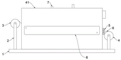
The invention discloses a plush blowing device for spinning, relates to the technical field of plush blowing, and aims to solve the problems that the prior plush blowing device can not completely remove the plush on a textile thread in the using process, and the textile thread is damaged due to excessive blowing force. The top of base is provided with blows off the mechanism, one side of blowing off the mechanism is provided with the feed inlet, one side of feed inlet is provided with the blowing roller, the opposite side of blowing off the mechanism is provided with the discharge gate, one side of discharge gate is provided with the guide roll, one side of guide roll is provided with the receipts material roller, it all passes through support and base fixed connection to receive material roller and blowing roller, it is connected through the yarn transmission between material roller and the blowing roller to receive the material roller, the inside of blowing off the mechanism is provided with the compression roller, and the compression roller is located the top of yarn, one side of compression roller is provided with pneumatic push rod one, the top of blowing off the mechanism is provided with the blast pipe, the preceding terminal surface of blowing off the mechanism is provided with the observation window.
Description
Technical Field
The invention relates to the technical field of plush blowing, in particular to a plush blowing device for spinning.
Background
The textile is a multi-scale structure processing technology of fiber or fiber aggregate, the most famous textile in China is like silk, the exchange of silk drives the exchange of culture in east and west and the development of traffic, the business and military in west are also indirectly influenced, the textile also comprises non-woven fabric technology, clothing and industrial textile produced by modern electrostatic nano-net forming technology and the like, the ancient textile and printing and dyeing technology in China has a very long history, ancient people have learned local materials for adapting to the change of climate in the early period of the original society, and the simple manual textile tool is manufactured by using natural resources as raw materials for textile and printing and dyeing, and clothes, airbags and curtains in daily life are products of the textile and printing and dyeing technology until today. In the production process of the textile plush cloth, a processing device is required to carry out scraping operation on the surface of the plush cloth, so that the flatness of the surface of the plush cloth is improved, the condition that plush particles fly in the subsequent process is avoided, and the environmental protection performance of a textile plush cloth production workshop is improved.
The existing lint blowing device can not completely remove lint on the textile thread in the using process, and some textile threads are damaged due to excessive blowing force; therefore, the existing requirements are not met, and a plush blowing device for spinning is proposed.
Disclosure of Invention
The invention aims to provide a plush blowing device for spinning, which solves the problems that the prior plush blowing device in the background art can not completely remove the plush on a textile thread in the using process and the textile thread is damaged due to excessive blowing force.
In order to achieve the purpose, the invention provides the following technical scheme: the utility model provides a pile blowing device is used in weaving, includes the base, the top of base is provided with the blowing mechanism, one side of blowing mechanism is provided with the feed inlet, one side of feed inlet is provided with blowing roller, the opposite side of blowing mechanism is provided with the discharge gate, one side of discharge gate is provided with the guide roll, one side of guide roll is provided with the receipts material roller, receipts material roller and blowing roller are all through support and base fixed connection, be connected through the yarn transmission between receipts material roller and the blowing roller, the inside of blowing mechanism is provided with the compression roller, and the compression roller is located the top of yarn, one side of compression roller is provided with pneumatic push rod one, the top of blowing mechanism is provided with the blast pipe, the preceding terminal surface of blowing mechanism is provided with the observation window.
Preferably, one side of the first pneumatic push rod is provided with a second pneumatic push rod, and one side of the second pneumatic push rod is provided with a water collecting chamber.
Preferably, the lower surface of the first pneumatic push rod is provided with a first pressing plate, and a scraper is fixedly arranged below the first pressing plate.
Preferably, the fixed spray pipe that is provided with in below of collecting chamber, the fixed shower nozzle that is provided with in below of spray pipe, the front end and the rear end of spray pipe all fix and are provided with the fixed plate, the inboard of fixed plate is provided with the fly leaf, the fly leaf passes through spout and collecting chamber sliding connection, the fixed pressure spring that is provided with between fly leaf and the fixed plate, and the pressure spring is provided with four, the fixed stopper that is provided with of one end of spout, the inboard of fly leaf is fixed and is provided with anchor clamps, and anchor clamps are located the outer wall of yarn.
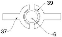
Preferably, the inner wall of the clamp is provided with a wool removing layer, a water tank is arranged below the clamp, a water collecting hopper is fixedly arranged on the upper surface of the water tank, a filter screen is arranged inside the water collecting hopper, the water tank is fixedly connected with a water collecting chamber through a circulating water pipe, and a water pump is arranged on the circulating water pipe.
Preferably, one side of water tank is provided with inhales the wadding pipe, the fixed collection wadding case that is provided with in one side of inhaling the wadding pipe, the last surface connection who inhales the wadding pipe has inhales the wadding cover, and inhales the wadding cover and be provided with four, the inside of collection wadding case is provided with the aspirator pump, and the aspirator pump with inhale wadding pipe fixed connection.
Preferably, one side of the water collecting chamber is provided with an air cooler, an air inlet is formed above the air cooler, and a dust screen is arranged inside the air inlet.
Preferably, the lower surface of the second pneumatic push rod is provided with a second pressing plate, the lower surface of the second pressing plate is provided with a heating plate, and the second pneumatic push rod and the first pneumatic push rod are fixedly connected with the blowing mechanism through mounting seats.
Compared with the prior art, the invention has the beneficial effects that:
1. according to the invention, the first pressing plate can be driven to be close to the yarn through the telescopic motion of the first pneumatic push rod, so that the scraping plate scrapes the wool on the yarn, the second pressing plate can be driven to be close to the yarn through the telescopic motion of the second pneumatic push rod, the clean wool is left on the yarn by the scraping plate, and the wool removing effect is better through the heating of the heating plate.
2. Through the setting of blast pipe, the blast pipe is convenient for the heat exchange of air, avoids blowing off the high in-process that leads to the yarn to cause the damage to the yarn at the unhairing of mechanism inside temperature, and the staff of being convenient for of observation window observes the unhairing process, and the guide roll has played the effect of direction, and the compression roller can make the yarn produce certain pretension, avoids the yarn to skid.
3. Through the setting that removes the matte layer, the yarn can be handled yarn wool on the surface at driven in-process anchor clamps, setting through the drip chamber, the spray pipe can pass through the shower nozzle with the water in the drip chamber and spout to the yarn, thereby wash out glutinous batting on the yarn, the water collecting bucket can concentrate the water of having washed to the water tank in, so that the reutilization, the filter screen filters the impurity in with the sewage, then by inside the water pump gets into the drip chamber through circulating water pipe, the effect of hydrologic cycle has been reached, practice thrift the environmental protection.
4. Through setting up the air-cooler, the air-cooler can air-dry the processing to the yarn that is soaked by the water logging, is convenient for receive the material, and the dust screen has played dirt-proof effect, avoids bringing external dust into in the blowdown mechanism.
5. Through the setting of collection wadding case, can make the aspirator pump will blow off the inside floated batting of mechanism and inhale in the wadding pipe, played the effect that removes the wadding, four inhale the wadding cover and improved and removed wadding efficiency for it is better to remove the wadding effect, avoids the batting to adsorb on the yarn once more.
6. Through removing the fly leaf, can make anchor clamps grasp the yarn, the stability that the slip fit of fly leaf and spout has improved anchor clamps, the pressure spring has played the effect that resets, and the stopper has played spacing effect to the fly leaf.
Drawings
FIG. 1 is a schematic view of the overall structure of the present invention;
FIG. 2 is a schematic view of the internal structure of the present invention;
FIG. 3 is a schematic diagram of a side view of the water collection chamber of the present invention;
FIG. 4 is a schematic view of the structure of the hair removal layer of the present invention;
FIG. 5 is a schematic view of the internal structure of the catkin collecting box of the present invention;
in the figure: 1. a base; 2. a support; 3. a discharging roller; 4. a material receiving roller; 5. a guide roller; 6. a yarn; 7. an exhaust pipe; 8. an observation window; 9. a feed inlet; 10. a discharge port; 11. pressing rollers; 12. a mounting seat; 13. a first pneumatic push rod; 14. a second pneumatic push rod; 15. pressing a first plate; 16. a squeegee; 17. pressing a second plate; 18. heating the plate; 19. a cotton suction pipe; 20. a cotton wool suction cover; 21. a wadding collecting box; 22. a water tank; 23. a water collecting hopper; 24. a circulating water pipe; 25. a water collection chamber; 26. an air inlet; 27. a dust screen; 28. an air cooler; 29. a water pump; 30. a fixing plate; 31. a pressure spring; 32. a movable plate; 33. a chute; 34. a limiting block; 35. a water spray pipe; 36. a spray head; 37. a clamp; 38. a filter screen; 39. removing a wool layer; 40. a getter pump; 41. a blowing mechanism.
Detailed Description
The technical solutions in the embodiments of the present invention will be clearly and completely described below with reference to the drawings in the embodiments of the present invention, and it is obvious that the described embodiments are only a part of the embodiments of the present invention, and not all of the embodiments.
Referring to fig. 1-5, an embodiment of the present invention is shown: a plush blowing device for spinning comprises a base 1, a blowing mechanism 41 is arranged above the base 1, a feed inlet 9 is formed in one side of the blowing mechanism 41, a discharge roller 3 is arranged on one side of the feed inlet 9, a discharge port 10 is formed in the other side of the blowing mechanism 41, a guide roller 5 is arranged on one side of the discharge port 10, the guide roller 5 plays a role in guiding, a receiving roller 4 is arranged on one side of the guide roller 5, the receiving roller 4 and the discharge roller 3 are both fixedly connected with the base 1 through a support 2, the support 2 plays a role in supporting, the receiving roller 4 is in transmission connection with the discharge roller 3 through yarns 6, a compression roller 11 is arranged inside the blowing mechanism 41, the compression roller 11 is positioned above the yarns 6, the compression roller 11 can enable the yarns 6 to generate certain pretension force, slipping of the yarns 6 is avoided, a pneumatic push rod 13 is arranged on one side of the compression roller 11, an exhaust pipe 7 is arranged above the blowing mechanism 41, an observation window 8 is arranged on the front end face of the blowing mechanism 41, the exhaust pipe 7 facilitates heat exchange of air, the phenomenon that the internal temperature of the blowing mechanism 41 is too high, and an electromagnetic valve is arranged inside of the exhaust pipe 6 in the wool removing process, and observation window 7 can be used for controlling the flowing of a worker and a working process of the wool removing solenoid valve and a wool removing solenoid valve.
Further, one side of the first pneumatic push rod 13 is provided with a second pneumatic push rod 14, one side of the second pneumatic push rod 14 is provided with a water collecting chamber 25, and the water collecting chamber 25 plays a role in collecting water.
Furthermore, a first pressing plate 15 is arranged on the lower surface of the first pneumatic push rod 13, a scraper 16 is fixedly arranged below the first pressing plate 15, and the first pressing plate 15 can be driven to be close to the yarn 6 by the telescopic motion of the first pneumatic push rod 13, so that the scraper 16 scrapes off hairs on the yarn 6.
Further, a spray pipe 35 is fixedly arranged below the water collecting chamber 25, a spray head 36 is fixedly arranged below the spray pipe 35, a fixed plate 30 is fixedly arranged at the front end and the rear end of the spray pipe 35, a movable plate 32 is arranged on the inner side of the fixed plate 30, the movable plate 32 is slidably connected with the water collecting chamber 25 through a chute 33, a pressure spring 31 is fixedly arranged between the movable plate 32 and the fixed plate 30, four pressure springs 31 are arranged, a limit block 34 is fixedly arranged at one end of the chute 33, a clamp 37 is fixedly arranged on the inner side of the movable plate 32, the clamp 37 is positioned on the outer wall of the yarn 6, the yarn 6 can treat the hair on the surface of the yarn 6 in the transmission process through the clamp 37, the spray pipe 35 can spray the water in the water collecting chamber 25 to the yarn 6 through the spray head 36, so that the hair adhered to the yarn 6 is washed clean, the yarn 6 can be clamped by driving the clamp 37 through horizontally moving the two movable plates 32, the movable plates 32 and the chute 33 are in sliding fit, so that the stability of the clamp 37 during movement is improved, the pressure spring 31 plays a reset effect after the external force disappears, and the limit of the limit block 34 plays a limiting effect on the movable plates 32.
Further, the inner wall of anchor clamps 37 is provided with the unhairing layer 39, the below of anchor clamps 37 is provided with water tank 22, the fixed surface of water tank 22 is provided with water collecting bucket 23, the inside of water collecting bucket 23 is provided with filter screen 38, water tank 22 passes through circulating pipe 24 and water-collecting chamber 25 fixed connection, be provided with water pump 29 on the circulating pipe 24, unhairing layer 39 has played the effect of removing the hair, water collecting bucket 23 can concentrate the water that washes and collect and deliver to in water tank 22, so that the reutilization, filter screen 38 can carry out effectual filtration with the impurity in the sewage, then carry to the inside of water-collecting chamber 25 through circulating pipe 24 high pressure by water pump 29 again, the effect of hydrologic cycle has been reached, practice thrift the environmental protection, filter screen 38 can dismantle, so that regularly clearance prevents to block up.
Further, one side of water tank 22 is provided with inhales the wadding pipe 19, inhale fixed collection wadding case 21 that is provided with in one side of wadding pipe 19, the last surface connection who inhales wadding pipe 19 has inhales the wadding cover 20, and inhale wadding cover 20 and be provided with four, the inside of collection wadding case 21 is provided with aspirator pump 40, and aspirator pump 40 with inhale wadding pipe 19 fixed connection, collection wadding case 21 will blow off the inside showy batting of mechanism 41 through aspirator pump 40 and inhale in the wadding pipe 19, the effect of removing the wadding has been played, four inhale wadding covers 20 and have improved and have removed wadding efficiency, make it better to remove the wadding effect, avoid the batting to adsorb on yarn 6 once more.
Further, an air cooler 28 is arranged on one side of the water collecting chamber 25, an air inlet 26 is arranged above the air cooler 28, a dustproof net 27 is arranged inside the air inlet 26, the air cooler 28 can carry out air drying treatment on the yarns 6 soaked by water, material collection is facilitated, external air can be conveniently introduced into the air cooler 28 through the air inlet 26, the dustproof net 27 plays a dustproof role, and external dust is prevented from being brought into the blowing mechanism 41.
Further, the lower surface of the second pneumatic push rod 14 is provided with a second pressing plate 17, the lower surface of the second pressing plate 17 is provided with a heating plate 18, the second pneumatic push rod 14 and the first pneumatic push rod 13 are fixedly connected with the blowing mechanism 41 through the mounting seat 12, the second pneumatic push rod 14 can drive the second pressing plate 17 to be close to the yarn 6 through telescopic motion, a scraper 16 is left on the yarn 6 and does not scrape clean lint, the lint removing effect is better through heating of the heating plate 18, and the mounting seat 12 facilitates installation of the second pneumatic push rod 14 and the first pneumatic push rod 13.
The working principle is as follows: when the device is used, the yarn 6 on the discharging roller 3 enters the blowing mechanism 41 from the feeding hole 9 and is transmitted with the receiving roller 4 through the discharging hole 10, the compression roller 11 can enable the yarn 6 to generate certain pretension force to avoid the yarn 6 from slipping, the guide roller 5 plays a role of guiding, the first pressing plate 15 can be driven to be close to the yarn 6 through the telescopic motion of the first pneumatic push rod 13, so that the scraping plate 16 can scrape the hair on the yarn 6, the second pressing plate 17 can be driven to be close to the yarn 6 through the telescopic motion of the second pneumatic push rod 14, the yarn 6 is left with the hair flocks which are not scraped completely by the scraping plate 16, the hair removing effect is better through the heating of the heating plate 18, through the arrangement of the exhaust pipe 7, the exhaust pipe 7 is convenient for the heat exchange of air, the phenomenon that the yarn 6 is damaged in the hair removing process due to overhigh internal temperature of the blowing mechanism 41 is avoided, the observation window 8 is convenient for a worker to observe the hair removing process, through moving the movable plate 32, the yarn 6 can be clamped by the clamp 37, the movable plate 32 is in sliding fit with the chute 33, the stability of the clamp 37 is improved, the pressure spring 31 has a resetting effect, the limiting block 34 has a limiting effect on the movable plate 32, through the arrangement of the wool removing layer 39, the clamp 37 can treat the wool on the surface of the yarn 6 in the transmission process of the yarn 6, through the arrangement of the water collecting chamber 25, the water in the water collecting chamber 25 can be sprayed to the yarn 6 through the spray head 36 by the water spraying pipe 35, so that the wool adhered to the yarn 6 is washed clean, the washed water can be concentrated into the water tank 22 by the water collecting hopper 23 for secondary utilization, the impurities in the sewage are filtered by the filter screen 38, and then the water enters the water collecting chamber 25 through the circulating water pipe 24 by the water pump 29, the water circulation effect is achieved, and the effects of water circulation are saved and environmental protection are achieved, through setting up air-cooler 28, air-cooler 28 can air-dry the processing to the yarn 6 that is soaked by the water logging, be convenient for receive the material, dust screen 27 has played dirt-proof effect, avoid bringing external dust into in blowing off mechanism 41, setting through collection wadding case 21, can make aspirator pump 40 will blow off the inside floated batting of mechanism 41 and inhale in inhaling wadding pipe 19, the effect that removes the batting has been played, four inhale wadding covers 20 and have improved and remove wadding efficiency, make and remove the wadding effect better, avoid the batting to adsorb on yarn 6 once more.
It will be evident to those skilled in the art that the invention is not limited to the details of the foregoing illustrative embodiments, and that the present invention may be embodied in other specific forms without departing from the spirit or essential attributes thereof. The present embodiments are therefore to be considered in all respects as illustrative and not restrictive, the scope of the invention being indicated by the appended claims rather than by the foregoing description, and all changes which come within the meaning and range of equivalency of the claims are therefore intended to be embraced therein. Any reference sign in a claim should not be construed as limiting the claim concerned.
Claims (2)
1. A lint blowing device for spinning comprises a base (1), and is characterized in that: a blowing mechanism (41) is arranged above the base (1), a feeding hole (9) is formed in one side of the blowing mechanism (41), a discharging roller (3) is arranged on one side of the feeding hole (9), a discharging hole (10) is formed in the other side of the blowing mechanism (41), a guide roller (5) is arranged on one side of the discharging hole (10), a receiving roller (4) is arranged on one side of the guide roller (5), the receiving roller (4) and the discharging roller (3) are fixedly connected with the base (1) through a support (2), the receiving roller (4) and the discharging roller (3) are in transmission connection through yarns (6), a compression roller (11) is arranged inside the blowing mechanism (41), the compression roller (11) is located above the yarns (6), a pneumatic push rod I (13) is arranged on one side of the compression roller (11), a pneumatic push rod II (14) is arranged on one side of the pneumatic push rod I (13), and a water collecting chamber (25) is arranged on one side of the pneumatic push rod II (14);
a spray pipe (35) is fixedly arranged below the water collecting chamber (25), a spray head (36) is fixedly arranged below the spray pipe (35), fixed plates (30) are fixedly arranged at the front end and the rear end of the spray pipe (35), movable plates (32) are arranged on the inner sides of the fixed plates (30), the movable plates (32) are slidably connected with the water collecting chamber (25) through sliding grooves (33), compression springs (31) are fixedly arranged between the movable plates (32) and the fixed plates (30), four compression springs (31) are arranged, a limiting block (34) is fixedly arranged at one end of each sliding groove (33), clamps (37) are fixedly arranged on the inner sides of the movable plates (32), and the clamps (37) are located on the outer wall of the yarn (6); a fur removing layer (39) is arranged on the inner wall of the clamp (37), a water tank (22) is arranged below the clamp (37), a water collecting hopper (23) is fixedly arranged on the upper surface of the water tank (22), a filter screen (38) is arranged inside the water collecting hopper (23), the water tank (22) is fixedly connected with a water collecting chamber (25) through a circulating water pipe (24), and a water pump (29) is arranged on the circulating water pipe (24); a cotton wool suction pipe (19) is arranged on one side of the water tank (22), a cotton wool collection box (21) is fixedly arranged on one side of the cotton wool suction pipe (19), a cotton wool suction cover (20) is connected to the upper surface of the cotton wool suction pipe (19), four cotton wool suction covers (20) are arranged, a suction pump (40) is arranged inside the cotton wool collection box (21), and the suction pump (40) is fixedly connected with the cotton wool suction pipe (19);
a second pressure plate (17) is arranged on the lower surface of the second pneumatic push rod (14), a heating plate (18) is arranged on the lower surface of the second pressure plate (17), and the second pneumatic push rod (14) and the first pneumatic push rod (13) are fixedly connected with a blowing mechanism (41) through a mounting seat (12);
an exhaust pipe (7) is arranged above the blowing mechanism (41), an observation window (8) is arranged on the front end face of the blowing mechanism (41), a first pressing plate (15) is arranged on the lower surface of the first pneumatic push rod (13), and a scraper (16) is fixedly arranged below the first pressing plate (15);
when the device is used, the yarn (6) on the discharging roller (3) enters the blowing mechanism (41) from the feeding hole (9) and is transmitted with the collecting roller (4) through the discharging hole (10), the compression roller (11) can enable the yarn (6) to generate certain pretension, the yarn (6) is prevented from slipping, the guide roller (5) plays a role in guiding, the pressing plate I (15) can be driven to be close to the yarn (6) through the telescopic motion of the pneumatic push rod I (13), so that the scraping plate (16) can scrape the wool on the yarn (6), the pressing plate II (17) can be driven to be close to the yarn (6) through the telescopic motion of the pneumatic push rod II (14), the scraping plate (16) is still left on the yarn (6) and is not scraped with clean wool, the wool is better in the hair removing effect through the heating of the heating plate (18), the hair removing effect is achieved, the exhaust pipe (7) is arranged, the exhaust pipe (7) facilitates the heat exchange of air, the heat exchange of the air is avoided, the situation that the yarn (6) is damaged in the hair removing process caused by the fact that the yarn (6) due to overhigh internal temperature of the blowing mechanism (41), the movable plate (32) and the movable plate (32) can improve the stability of the movable clamp (32), and the limiting chute (32), and the movable plate (32) and can be matched with the limiting effect of the movable plate (32), through the setting that removes hair layer (39), yarn (6) can be handled yarn (6) the surperficial hair at driven in-process anchor clamps (37), setting through collecting chamber (25), spray pipe (35) can pass through shower nozzle (36) with the water in collecting chamber (25) and spout to yarn (6), thereby wash glutinous batting on yarn (6), water collecting hopper (23) can be concentrated the water of having washed in to water tank (22), so that the reutilization, impurity in filter screen (38) the sewage is filtered, then get into collecting chamber (25) inside through circulating water pipe (24) by water pump (29) again, reached the effect of hydrologic cycle, practice thrift the environmental protection.
2. A pile blowing device for textile use according to claim 1, characterized in that: one side of water collecting chamber (25) is provided with air-cooler (28), the top of air-cooler (28) is provided with air intake (26), the inside of air intake (26) is provided with dust screen (27).
Priority Applications (1)
| Application Number | Priority Date | Filing Date | Title |
|---|---|---|---|
| CN202011291650.8A CN112391715B (en) | 2020-11-18 | 2020-11-18 | Plush blowing device for spinning |
Applications Claiming Priority (1)
| Application Number | Priority Date | Filing Date | Title |
|---|---|---|---|
| CN202011291650.8A CN112391715B (en) | 2020-11-18 | 2020-11-18 | Plush blowing device for spinning |
Publications (2)
| Publication Number | Publication Date |
|---|---|
| CN112391715A CN112391715A (en) | 2021-02-23 |
| CN112391715B true CN112391715B (en) | 2022-10-25 |
Family
ID=74607263
Family Applications (1)
| Application Number | Title | Priority Date | Filing Date |
|---|---|---|---|
| CN202011291650.8A Active CN112391715B (en) | 2020-11-18 | 2020-11-18 | Plush blowing device for spinning |
Country Status (1)
| Country | Link |
|---|---|
| CN (1) | CN112391715B (en) |
Families Citing this family (2)
| Publication number | Priority date | Publication date | Assignee | Title |
|---|---|---|---|---|
| CN114737292B (en) * | 2022-04-24 | 2023-07-07 | 徐州国华纺织科技有限公司 | Impurity removing equipment for cotton yarn production and manufacturing |
| CN116835382B (en) * | 2023-09-01 | 2023-11-03 | 常州虹纬纺织有限公司 | Core spun yarn winding device and working method thereof |
Family Cites Families (9)
| Publication number | Priority date | Publication date | Assignee | Title |
|---|---|---|---|---|
| JPH0726438A (en) * | 1993-07-13 | 1995-01-27 | Toray Ind Inc | Yarn interlacing device with washing mechanism and method for automatic washing of the same in yarn production process |
| WO2002050358A1 (en) * | 2000-12-19 | 2002-06-27 | M & J Fibretech A/S | Plant for removing fines from fibre fluff |
| CN207121673U (en) * | 2017-06-29 | 2018-03-20 | 华瑞(中国)缝纫线有限公司 | A kind of clear suede device of spinning frame |
| CN108118420A (en) * | 2017-12-28 | 2018-06-05 | 苏州朦井纺织科技有限公司 | A kind of Weaving device convenient for cleaning |
| CN209082091U (en) * | 2018-10-17 | 2019-07-09 | 嘉兴市鸣业纺织有限公司 | A kind of sectional warper |
| CN210826521U (en) * | 2019-07-30 | 2020-06-23 | 枣阳市吉顺纺织有限公司 | Cotton removing device for twisting cotton yarn |
| CN211311714U (en) * | 2019-10-12 | 2020-08-21 | 张家港扬子纺纱有限公司 | Spinning frame with velvet cleaning device |
| CN211497929U (en) * | 2019-12-30 | 2020-09-15 | 阜宁县荣泰纺织品有限公司 | High strength cotton yarn processing is with removing wadding device |
| CN111519305A (en) * | 2020-04-28 | 2020-08-11 | 林梅仙 | Safe weaving yarn cleaning device |
-
2020
- 2020-11-18 CN CN202011291650.8A patent/CN112391715B/en active Active
Also Published As
| Publication number | Publication date |
|---|---|
| CN112391715A (en) | 2021-02-23 |
Similar Documents
| Publication | Publication Date | Title |
|---|---|---|
| CN112391715B (en) | Plush blowing device for spinning | |
| CN108118420A (en) | A kind of Weaving device convenient for cleaning | |
| CN212247587U (en) | A unhairing wool-absorbing device for weaving printing and dyeing | |
| CN201287015Y (en) | Self-cleaning device of filter net | |
| CN109487519A (en) | Mercerizing equipment | |
| CN113123036A (en) | Textile clothing is with destatic weaving defeathering device | |
| CN116334861A (en) | Textile steam cleaning device | |
| CN203855695U (en) | Cotton spinning impurity removing device | |
| CN215829117U (en) | Weaving cotton fibre and dust cleaning device | |
| CN213951620U (en) | Textile fabric surface dust removing device | |
| CN214400847U (en) | Rotor spinning machine with dust removal effect | |
| CN212041604U (en) | Cleaning equipment for textile machinery | |
| CN211515511U (en) | Textile waste collection device | |
| CN205741295U (en) | A kind of cotton gin of stable performance | |
| CN204690449U (en) | A kind of stentering forming Electrical Control dust pelletizing system | |
| CN210569752U (en) | Textile fabric dust removal drying device | |
| CN209039831U (en) | A kind of cotton product removal of impurities adsorbent equipment | |
| CN204000383U (en) | A kind of fabric is except fine structure | |
| CN110528214A (en) | A kind of fabric dust-extraction unit | |
| CN220724651U (en) | High-efficient dust removal mechanism for cotton processing | |
| CN220229938U (en) | Water suction structure of water jet loom | |
| CN220394046U (en) | Grey cloth warp knitting machine convenient for removing plush | |
| CN216558141U (en) | Weaving cloth quick drying device | |
| CN220746297U (en) | Cotton yarn impurity separation box | |
| CN219930544U (en) | Textile dust removal device |
Legal Events
| Date | Code | Title | Description |
|---|---|---|---|
| PB01 | Publication | ||
| PB01 | Publication | ||
| SE01 | Entry into force of request for substantive examination | ||
| SE01 | Entry into force of request for substantive examination | ||
| TA01 | Transfer of patent application right |
Effective date of registration: 20221010 Address after: No. 26, Chengliu Road, Mingcheng Town, Gaoming District, Foshan City, Guangdong Province, 528500 (General Assembly Workshop I) (application for residence) Applicant after: Foshan Gaoming Longxu Flocking Processing Co.,Ltd. Address before: Room 201, unit 1, building 22, Runzhou Huayuan District 1, yonganzhou Town, Gaogang District, Taizhou City, Jiangsu Province Applicant before: Zhou Shuanglong |
|
| TA01 | Transfer of patent application right | ||
| GR01 | Patent grant | ||
| GR01 | Patent grant |