CN112273818A - Be used for wooden string of beads of jewelry to add processingequipment in batches - Google Patents
Be used for wooden string of beads of jewelry to add processingequipment in batches Download PDFInfo
- Publication number
- CN112273818A CN112273818A CN202011338722.XA CN202011338722A CN112273818A CN 112273818 A CN112273818 A CN 112273818A CN 202011338722 A CN202011338722 A CN 202011338722A CN 112273818 A CN112273818 A CN 112273818A
- Authority
- CN
- China
- Prior art keywords
- frame
- bottom plate
- rack
- jewelry
- support frame
- Prior art date
- Legal status (The legal status is an assumption and is not a legal conclusion. Google has not performed a legal analysis and makes no representation as to the accuracy of the status listed.)
- Pending
Links
- 241001146209 Curio rowleyanus Species 0.000 title claims description 10
- 239000000463 material Substances 0.000 claims abstract description 24
- 239000011324 bead Substances 0.000 claims abstract description 21
- 238000005520 cutting process Methods 0.000 claims abstract description 17
- 230000005540 biological transmission Effects 0.000 claims description 20
- 238000003825 pressing Methods 0.000 claims description 12
- 230000008602 contraction Effects 0.000 claims description 6
- 238000004080 punching Methods 0.000 claims description 5
- 239000011049 pearl Substances 0.000 claims 5
- 239000002023 wood Substances 0.000 abstract description 20
- 238000000034 method Methods 0.000 abstract description 18
- 238000010923 batch production Methods 0.000 description 2
- 230000000694 effects Effects 0.000 description 2
- 238000004519 manufacturing process Methods 0.000 description 2
- 239000002699 waste material Substances 0.000 description 2
- 241000750718 Pterocarpus santalinus Species 0.000 description 1
- 230000007547 defect Effects 0.000 description 1
- 238000007599 discharging Methods 0.000 description 1
- 238000000605 extraction Methods 0.000 description 1
- 238000012986 modification Methods 0.000 description 1
- 230000004048 modification Effects 0.000 description 1
- 238000006467 substitution reaction Methods 0.000 description 1
Images


Classifications
-
- A—HUMAN NECESSITIES
- A44—HABERDASHERY; JEWELLERY
- A44C—PERSONAL ADORNMENTS, e.g. JEWELLERY; COINS
- A44C27/00—Making jewellery or other personal adornments
Abstract
The invention relates to a device for batch processing of beads, in particular to a device for batch processing of jewelry wood beads. The invention aims to solve the technical problem of providing a batch processing device for jewelry wooden beads, which reduces the labor intensity of workers, improves the working efficiency, processes fixed-length wood and can automatically feed materials. In order to solve the technical problem, the invention provides a jewelry wood bead batch processing device, which comprises: a stop block is arranged on one side of the top of the bottom plate; the driving mechanism is arranged on one side of the top of the bottom plate; and the rotating mechanism is arranged in the middle of the top of the bottom plate. According to the invention, through the matching of the driving mechanism, the rotating mechanism, the cutting mechanism and the blanking mechanism, the wood can be processed into the beads, the cutting knife does not need to be moved by workers, and the labor amount of the workers is reduced.
Description
Technical Field
The invention relates to a device for batch processing of beads, in particular to a device for batch processing of jewelry wood beads.
Background
The pterocarpus santalinus, the hastate yam and the yellower hand string are not easy to deform and crack due to the fine wood and high oil content. The disc is not used with any oil.
The production manufacturing work of wooden string of beads is now generally that machine tooling accomplishes, original processing machine needs the workman to carry out material loading work, will wait to process timber and place in processing mouthful department before starting the machine, manual tightening presss from both sides tight department, start the machine operation, be close to the cutting knife and wait to process timber, process it, wait to process and stop the machine operation after accomplishing, the string of beads after accomplishing will process is taken off, loosen timber and press from both sides tight department, take out certain length with timber, press from both sides tightly once more, repeat above-mentioned process, until with all after waiting to process timber processing, close the machine, above-mentioned operation process is comparatively loaded down with trivial details, workman intensity of labour is big, work efficiency is low, and take out the unable accurate control of length, easily cause the waste of material, timber also needs the manual work to carry out material loading work.
Therefore, the device for processing the jewelry wooden beads in batches, which reduces the labor intensity of workers, improves the working efficiency, processes the fixed-length wood and can automatically feed, needs to be designed and manufactured.
Disclosure of Invention
(1) Technical problem to be solved
The invention aims to overcome the defects that the labor intensity of workers is high, the working efficiency is low, the extraction length cannot be accurately controlled, the material waste is easily caused, and the wood needs to be manually fed in the bead processing process.
(2) Technical scheme
In order to solve the technical problem, the invention provides a jewelry wood bead batch processing device, which comprises: a stop block is arranged on one side of the top of the bottom plate; the driving mechanism is arranged on one side of the top of the bottom plate; the rotating mechanism is arranged in the middle of the top of the bottom plate; the cutting mechanism is arranged on the other side of the top of the bottom plate; and the blanking mechanism is arranged close to one side of the bottom plate of the cutting mechanism.
Preferably, the drive mechanism comprises: the bottom frame is connected to one side of the top of the bottom plate; a servo motor connected to the chassis; a positioning block connected to one side of the chassis; the rotating shaft is connected to the positioning block in a rotating mode and is connected with an output shaft of the servo motor.
Preferably, the rotating mechanism comprises: the first support frame is connected to the middle of the top of the bottom plate; the fixture block gear is rotatably connected to the first support frame; and the transmission straight gear is connected to one end of the rotating shaft, and the fixture block gear is meshed with the transmission straight gear.
Preferably, the cutting mechanism comprises: the second support frame is connected to one side of the top of the bottom plate; the cylinder is connected to the second support frame; and the cutter is connected to the cylinder contraction rod.
Preferably, the blanking mechanism includes: the third support frame is connected to one side of the top of the bottom plate; a first straight gear rotatably connected to the third support frame; the one-way gear is connected to one end of the first straight gear; the first rack is connected to the cylinder contraction rod, and the one-way gear is meshed with the first rack; the first guide sliding frame is connected to one side of the third supporting frame; the second rack is connected to the first guide carriage in a sliding mode, and the first straight gear is meshed with the second rack; the punching cutter is connected to one side of the second rack frame; the fourth support frame is connected to the top of the third support frame; and the first spring is connected between the fourth supporting frame and the second rack frame.
Preferably, still including liftout mechanism, liftout mechanism is including: the fixing plate is connected to the other side of the top of the bottom plate; the ejector rod is connected to the fixing plate in a sliding manner; the top plate is connected to one end of the ejector rod; and a second spring connected between the fixed plate and the top plate.
Preferably, also include supporting mechanism, supporting mechanism includes: the wedge-shaped blocks are connected to the two sides of the top plate; the fifth supporting frame is connected to the middle of the top of the bottom plate; the material receiving frame is connected to the fifth support frame in a sliding manner; the top pressing block is connected to two sides of the material receiving frame; and the third spring is connected between the material receiving frame and the fifth supporting frame.
Preferably, the device further comprises a charging mechanism, wherein the charging mechanism comprises: the sixth supporting frame is connected to the middle of the top of the bottom plate; the charging rack is connected to the sixth supporting frame; and at least two connecting rods are arranged and are connected between the charging racks at uniform intervals.
Preferably, still including unloading mechanism, unloading mechanism is including: the limiting frame is connected to one side of the top of the bottom plate; the transmission rotating rod is rotatably connected to one side of the limiting frame; the second straight gear is connected to the bottom end of the transmission rotating rod; one side of the limiting frame is rotatably connected with a connecting rod which is connected between the other end of the connecting rod and one end of the transmission rotating rod, and the two bevel gears are meshed with each other; the third straight gear is connected to one end of the connecting rod; the second guide sliding frame is connected to one side of the top of the bottom plate; the rack push block is connected to the second guide sliding frame in a sliding mode, and the third straight-tooth wheel is meshed with the rack push block; the seventh supporting frame is connected to the middle of the top of the bottom plate; the third guide sliding frame is connected to the seventh supporting frame; and the third rack is connected to the third guide sliding frame in a sliding mode, one end of the third rack is connected with the wedge block, and the third rack is meshed with the second straight gear.
Preferably, still include screens mechanism, screens mechanism includes: the fixing frame is connected to one side of the limiting frame; the guide post is connected to the fixed frame in a sliding manner; and the fourth spring is connected between the fixed frame and the guide post.
(3) Advantageous effects
1. According to the invention, through the matching of the driving mechanism, the rotating mechanism, the cutting mechanism and the blanking mechanism, the wood can be processed into the beads, a cutter does not need to be moved by workers, the labor amount of the workers is reduced, and the working efficiency is improved.
2. Through the cooperation of the material ejecting mechanism and the supporting mechanism, the material can be pushed without manpower in the processing process, the labor amount of workers is reduced, and the working efficiency is further improved.
3. Through the cooperation of charging mechanism, unloading mechanism and screens mechanism, can reach the purpose of automatic unloading, alleviate workman intensity of labour, promote work efficiency by a wide margin, realize the purpose of wooden string of beads of batch production.
Drawings
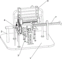
Fig. 1 is a schematic perspective view of a first embodiment of the present invention.
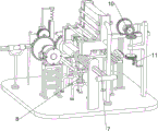
Fig. 2 is a schematic perspective view of a second embodiment of the present invention.
Fig. 3 is a third perspective view of the present invention.
Fig. 4 is a schematic perspective view of the driving mechanism and the rotating mechanism of the present invention.
Fig. 5 is a schematic perspective view of the cutting mechanism and the blanking mechanism according to the present invention.
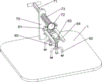
Fig. 6 is a schematic perspective view of the ejection mechanism and the supporting mechanism according to the present invention.
Fig. 7 is a perspective view of the charging mechanism of the present invention.
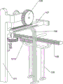
Fig. 8 is a schematic view of a first three-dimensional structure of the blanking mechanism and the clamping mechanism of the invention.
Fig. 9 is a schematic perspective view of a second three-dimensional structure of the blanking mechanism and the clamping mechanism of the present invention.
The labels in the figures are: 1-a bottom plate, 2-a stop block, 3-a driving mechanism, 31-a chassis, 32-a servo motor, 33-a positioning block, 34-a rotating shaft, 4-a rotating mechanism, 41-a first support frame, 42-a fixture gear, 43-a transmission spur gear, 5-a cutting mechanism, 51-a second support frame, 52-an air cylinder, 53-a cutter, 6-a blanking mechanism, 61-a third support frame, 62-a first straight gear, 63-a one-way gear, 64-a first rack frame, 65-a first guide frame, 66-a second rack frame, 67-a blanking cutter, 68-a fourth support frame, 69-a first spring, 7-a material ejecting mechanism, 70-a fixing plate, 71-an ejector rod, 72-a top plate and 73-a second spring, 8-supporting mechanism, 81-wedge block, 82-fifth supporting frame, 83-material receiving frame, 84-top pressing block, 85-third spring, 9-charging mechanism, 91-sixth supporting frame, 92-charging frame, 93-connecting rod, 10-discharging mechanism, 101-limiting frame, 102-transmission rotating rod, 103-second straight gear, 104-bevel gear, 105-third straight gear, 106-second guide carriage, 107-rack pushing block, 108-seventh supporting frame, 109-third guide carriage, 1010-third rack, 11-clamping mechanism, 1101-fixing frame, 1102-guide column, 1103-fourth spring.
Detailed Description
The invention is further described below with reference to the figures and examples.
Example 1
The utility model provides a be used for wooden string of beads of ornament to add processingequipment in batches, as shown in fig. 1 to 5, including bottom plate 1, dog 2, actuating mechanism 3, rotary mechanism 4, cutting mechanism 5 and blanking mechanism 6, dog 2 is installed on the left of 1 top of bottom plate, and actuating mechanism 3 is installed to 1 top front side of bottom plate, and rotary mechanism 4 is installed to the left side in the middle of 1 top of bottom plate, and cutting mechanism 5 is installed to 1 top left front side of bottom plate, and blanking mechanism 6 is installed to 1 top left front side of bottom plate.
The driving mechanism 3 comprises a bottom frame 31, a servo motor 32, a positioning block 33 and a rotating shaft 34, the bottom frame 31 is connected to the front side of the top of the bottom plate 1, the servo motor 32 is connected to the bottom frame 31, the positioning block 33 is connected to the left side of the bottom frame 31, the rotating shaft 34 is rotatably connected to the positioning block 33, and the rotating shaft 34 is connected with an output shaft of the servo motor 32.
The rotating mechanism 4 comprises a first support frame 41, a fixture block gear 42 and a transmission straight gear 43, the first support frame 41 is connected to the left of the middle of the top of the base plate 1, the fixture block gear 42 is rotatably connected to the first support frame 41, the fixture block gear 42 is located on the right side of the stop block 2, the transmission straight gear 43 is connected to the left end of the rotating shaft 34, and the fixture block gear 42 is meshed with the transmission straight gear 43.
The cutting mechanism 5 comprises a second supporting frame 51, a cylinder 52 and a cutter 53, the left front side of the top of the bottom plate 1 is connected with the second supporting frame 51, the cylinder 52 is connected onto the second supporting frame 51, the cutter 53 is connected onto a contraction rod of the cylinder 52, and the cutter 53 is located on the right front side of the stop block 2.
The blanking mechanism 6 comprises a third support frame 61, a first straight gear 62, a one-way gear 63, a first rack frame 64, a first guide carriage 65, a second rack frame 66, a blanking knife 67, a fourth support frame 68 and a first spring 69, the third support frame 61 is connected with the left front side of the top of the bottom plate 1, the first straight gear 62 is rotatably connected with the third support frame 61, the one-way gear 63 is connected with the left end of the first straight gear 62, the first rack frame 64 is connected with the contraction rod of the air cylinder 52, the one-way gear 63 is meshed with the first rack frame 64, the first guide carriage 65 is connected with the rear side of the third support frame 61, the second rack frame 66 is slidably connected with the first straight gear 62, the blanking knife 67 is connected with the rear side of the second rack frame 66, the blanking knife 67 is positioned above the left of the fixture block gear 42, the fourth support frame 68 is connected with the top of the third support frame 61, a first spring 69 is connected between the fourth support bracket 68 and the second rack bracket 66.
When the beading processing is required, the wood is pushed into the through hole of the fixture gear 42, the pushing is stopped after the wood touches the stop block 2, the servo motor 32 is started to rotate, the rotating shaft 34 drives the transmission spur gear 43 to rotate along with the rotation, the wood is rotated by meshing with the fixture gear 42, the air cylinder 52 is started to work at the same time, the cutter 53 is close to the wood for processing, the first rack frame 64 is meshed with the one-way gear 63, the first straight gear 62 cannot rotate along with the one-way gear 63 under the action of the one-way gear 63, after the wood processing is finished, the air cylinder 52 contracts to drive the first rack frame 64 to be reversely meshed with the one-way gear 63, the first straight gear 62 is meshed with the second rack frame 66, the second rack frame 66 slides on the first guide carriage 65 to drive the punching cutter 67 to move downwards, the first spring 69 is stretched to cut the joint of the wood and the finished beading, and when the first rack frame 64 is not meshed with, drive punching and cutting knife 67 under the effect of first spring 69 and reset, make things convenient for processing next time, can collect the string of beads of processing completion this moment, the manual work promotes timber left again, repeats above-mentioned operation process, with all timber processing completions backs of treating processing, with servo motor 32 and cylinder 52 stop work, so can process into the string of beads with timber, need not to remove the cutting knife at the workman, has reduced workman's the amount of labour, improves work efficiency.
Example 2
On the basis of embodiment 1, as shown in fig. 6, the ejection mechanism 7 is further included, the ejection mechanism 7 includes a fixing plate 70, an ejector rod 71, a top plate 72 and a second spring 73, the fixing plate 70 is connected to the right side of the top of the bottom plate 1, the ejector rod 71 is slidably connected to the fixing plate 70, the top plate 72 is connected to the left end of the ejector rod 71, the second spring 73 is connected between the fixing plate 70 and the top plate 72, and the second spring 73 is sleeved outside the ejector rod 71.
The material receiving device is characterized by further comprising a supporting mechanism 8, wherein the supporting mechanism 8 comprises a wedge block 81, a fifth supporting frame 82, a material receiving frame 83, a jacking block 84 and a third spring 85, the wedge block 81 is connected to the front side and the rear side of the top plate 72, the fifth supporting frame 82 is connected to the middle of the top of the bottom plate 1, the material receiving frame 83 is connected to the fifth supporting frame 82 in a sliding mode, the jacking block 84 is connected to the front side and the rear side of the material receiving frame 83, the jacking block 84 is connected with the wedge block 81, and the third spring 85 is connected between the material receiving frame 83 and the fifth.
The ejector rod 71 is pulled rightwards, the second spring 73 contracts, the wedge-shaped block 81 is contacted with the top pressing block 84, the third spring 85 is compressed in the initial state, when the wedge-shaped block 81 moves to be not contacted with the top pressing block 84, the top pressing block 84 moves to two sides of the material receiving frame 83 under the action of the third spring 85, the timber is placed on the material receiving frame 83, the top pressing block 84 has the limiting function, the ejector rod 71 is loosened, the timber is pushed by the top plate 72 under the action of the second spring 73 to be pushed to the through hole of the fixture block gear 42, the wedge-shaped block 81 is contacted with the top pressing block 84, the top pressing block 84 is continuously pushed by the wedge-shaped block 81, the top pressing block 84 is enabled to move downwards, the timber is prevented from being contacted with the top pressing block 84 in the rotating process, the servo motor 32 and the air cylinder 52 are started to process the timber, after the punching knife 67 separates beads from the processed timber, the top plate 72 continuously pushes the, the wood is placed at the fixed position by repeating the above processes with the next processing operation until all the wood to be processed is processed, and the servo motor 32 and the air cylinder 52 are closed, so that manual pushing in the processing process is not needed, the labor amount of workers is reduced, and the working efficiency is further improved.
Example 3
On the basis of embodiment 2, as shown in fig. 7 to 9, the loading device 9 is further included, the loading device 9 includes a sixth supporting frame 91, a loading frame 92 and a connecting rod 93, the sixth supporting frame 91 is connected to the middle of the top of the bottom plate 1, the loading frame 92 is connected to the sixth supporting frame 91, the bottom end of the loading frame 92 is located above the material receiving frame 83, and the connecting rods 93 are connected between the loading frames 92 at regular intervals.
The blanking mechanism 10 comprises a limiting frame 101, a transmission rotating rod 102, a second straight gear 103, a bevel gear 104, a third straight gear 105, a second guide carriage 106, a rack push block 107, a seventh support frame 108, a third guide carriage 109 and a third rack frame 1010, wherein the limiting frame 101 is connected with the rear side of the top of the bottom plate 1, the transmission rotating rod 102 is rotatably connected with the front side of the limiting frame 101, the second straight gear 103 is connected with the bottom end of the transmission rotating rod 102, the left side of the limiting frame 101 is rotatably connected with a connecting rod, the bevel gears 104 are uniformly connected with the right end of the connecting rod and the top end of the transmission rotating rod 102, the two bevel gears 104 are mutually meshed, the third straight gear 105 is connected with the left end of the connecting rod, the second guide carriage 106 is connected with the left rear side of the top of the bottom plate 1, the rack push block 107 is slidably connected with the second guide carriage 106, the rack push block 107 is positioned in a gap of the rear connecting rod 93, the third, the middle of the top of the bottom plate 1 is connected with a seventh supporting frame 108 in a rear-leaning mode, the seventh supporting frame 108 is connected with a third guide sliding frame 109, the third guide sliding frame 109 is connected with a third rack 1010 in a sliding mode, the front end of the third rack 1010 is connected with a wedge block 81, and the third rack 1010 is meshed with the second straight gear 103.
The clamping mechanism 11 is further included, the clamping mechanism 11 includes a fixing frame 1101, a guide post 1102 and a fourth spring 1103, the front side of the limiting frame 101 is connected with the fixing frame 1101, the guide post 1102 is connected on the fixing frame 1101 in a sliding manner, the guide post 1102 is located below the second spur gear 103, and the fourth spring 1103 is connected between the fixing frame 1101 and the guide post 1102.
When the wedge block 81 moves rightwards, the third rack 1010 slides on the third guide frame 109, when the wedge block 81 moves to be out of contact with the ejector pressing block 84, the third rack 1010 is meshed with the second straight gear 103, the second straight gear 103 rotates to touch the guide pillar 1102 to move downwards, the fourth spring 1103 is stretched, the bevel gear 104 is meshed through the transmission rotating rod 102 to drive the third straight gear 105 to be meshed with the rack pushing block 107, the rack pushing block 107 pushes the wood in the loading frame 92 forwards to enable the wood to fall onto the receiving block 83, the wedge block 81 moves leftwards, the third rack 1010 is meshed with the second straight gear 103 reversely to enable the rack pushing block 107 to reset, when the third rack 1010 is not meshed with the second straight gear 103, the second straight gear 103 resets, the guide pillar 1103 resets under the action of the fourth spring, fix second straight-teeth gear 103, so repeat above-mentioned action, can need not workman's material loading, can reach the purpose of automatic unloading, alleviate workman intensity of labour, promote work efficiency by a wide margin, realize the purpose of batch production wooden string of beads.
The above examples are merely representative of preferred embodiments of the present invention, and the description thereof is more specific and detailed, but not to be construed as limiting the scope of the present invention. It should be noted that, for those skilled in the art, various changes, modifications and substitutions can be made without departing from the spirit of the present invention, and these are all within the scope of the present invention. Therefore, the protection scope of the present patent shall be subject to the appended claims.
Claims (10)
1. The utility model provides a be used for wooden string of beads of jewelry batch processingequipment which characterized in that, including:
a bottom plate (1), wherein a stop block (2) is arranged on one side of the top of the bottom plate;
the driving mechanism (3) is arranged on one side of the top of the bottom plate (1);
the rotating mechanism (4) is arranged in the middle of the top of the bottom plate (1);
the cutting mechanism (5) is arranged on the other side of the top of the bottom plate (1);
and a blanking mechanism (6) which is installed close to one side of the bottom plate (1) of the cutting mechanism (5).
2. A batch processing device for jewelry wooden beads according to claim 1, wherein the driving mechanism (3) comprises:
a bottom frame (31) connected to one side of the top of the bottom plate (1);
a servo motor (32) connected to the base frame (31);
a positioning block (33) connected to one side of the chassis (31);
and a rotating shaft (34) rotatably connected to the positioning block (33), wherein the rotating shaft (34) is connected with an output shaft of the servo motor (32).
3. A batch processing device for jewelry wooden beads as claimed in claim 2, wherein the rotating mechanism (4) comprises:
the first support frame (41) is connected to the middle of the top of the bottom plate (1);
a latch gear (42) rotatably connected to the first support frame (41);
and the transmission straight gear (43) is connected to one end of the rotating shaft (34), and the fixture block gear (42) is meshed with the transmission straight gear (43).
4. A batch processing device for jewelry wooden beads according to claim 3, wherein the cutting mechanism (5) comprises:
a second support frame (51) connected to one side of the top of the bottom plate (1);
a cylinder (52) connected to the second support frame (51);
and the cutter (53) is connected to the contraction rod of the air cylinder (52).
5. A batch processing device for jewelry wooden beads according to claim 4, wherein the blanking mechanism (6) comprises:
a third support frame (61) connected to one side of the top of the bottom plate (1);
a first straight gear (62) rotatably connected to the third support frame (61);
a one-way gear (63) connected to one end of the first straight gear (62);
a first rack (64) connected to a contraction rod of the cylinder (52), wherein the one-way gear (63) is meshed with the first rack (64);
a first guide frame (65) connected to one side of the third support frame (61);
a second rack (66) slidably connected to the first guide frame (65), the first spur gear (62) meshing with the second rack (66);
a punching knife (67) connected to one side of the second rack (66);
a fourth support frame (68) connected to the top of the third support frame (61);
and a first spring (69) connected between the fourth support frame (68) and the second rack frame (66).
6. The batch processing device for jewelry wooden beads on pearls as claimed in claim 5, further comprising an ejecting mechanism (7), wherein the ejecting mechanism (7) comprises:
a fixing plate (70) connected to the other side of the top of the base plate (1);
a push rod (71) connected to the fixing plate (70) in a sliding manner;
a top plate (72) connected to one end of the jack (71);
and a second spring (73) connected between the fixing plate (70) and the top plate (72).
7. The batch processing device for jewelry wooden beads on pearls as claimed in claim 6, further comprising a supporting mechanism (8), wherein the supporting mechanism (8) comprises:
wedge blocks (81) connected to both sides of the top plate (72);
a fifth supporting frame (82) connected to the middle of the top of the bottom plate (1);
a material receiving frame (83) which is connected to the fifth support frame (82) in a sliding manner;
the top pressing blocks (84) are connected to the two sides of the material receiving frame (83);
and the third spring (85) is connected between the material receiving frame (83) and the fifth supporting frame (82).
8. The batch processing device for jewelry wooden beads on pearls as claimed in claim 7, further comprising a loading mechanism (9), wherein the loading mechanism (9) comprises:
the sixth supporting frame (91) is connected to the middle of the top of the bottom plate (1);
a charging rack (92) connected to the sixth support frame (91);
and at least two connecting rods (93) are arranged and are connected between the charging racks (92) at regular intervals.
9. The batch processing device for jewelry wooden beads on pearls as claimed in claim 8, further comprising a blanking mechanism (10), wherein the blanking mechanism (10) comprises:
the limiting frame (101) is connected to one side of the top of the bottom plate (1);
a transmission rotating rod (102) which is rotatably connected to one side of the limiting frame (101);
the second straight gear (103) is connected to the bottom end of the transmission rotating rod (102);
the bevel gears (104), one side of the limiting frame (101) is rotatably connected with a connecting rod, the connecting rod is connected between the other end of the connecting rod and one end of the transmission rotating rod (102), and the two bevel gears (104) are meshed with each other;
a third spur gear (105) connected to one end of the connecting rod;
a second guide frame (106) connected to the top side of the bottom plate (1);
a rack push block (107) which is connected to the second guide carriage (106) in a sliding manner, and the third straight gear (105) is meshed with the rack push block (107);
a seventh supporting frame (108) connected to the middle of the top of the bottom plate (1);
a third guide frame (109) connected to a seventh support frame (108);
and a third rack (1010) which is slidably connected to the third guide frame (109), one end of the third rack (1010) is connected with the wedge block (81), and the third rack (1010) is meshed with the second straight gear (103).
10. The batch processing device for jewelry wooden beads on pearls as claimed in claim 9, further comprising a clamping mechanism (11), wherein the clamping mechanism (11) comprises:
a fixing frame (1101) connected to one side of the limiting frame (101);
a guide post (1102) slidably coupled to the holder (1101);
and a fourth spring (1103) connected between the fixing frame (1101) and the guide post (1102).
Priority Applications (1)
| Application Number | Priority Date | Filing Date | Title |
|---|---|---|---|
| CN202011338722.XA CN112273818A (en) | 2020-11-25 | 2020-11-25 | Be used for wooden string of beads of jewelry to add processingequipment in batches |
Applications Claiming Priority (1)
| Application Number | Priority Date | Filing Date | Title |
|---|---|---|---|
| CN202011338722.XA CN112273818A (en) | 2020-11-25 | 2020-11-25 | Be used for wooden string of beads of jewelry to add processingequipment in batches |
Publications (1)
| Publication Number | Publication Date |
|---|---|
| CN112273818A true CN112273818A (en) | 2021-01-29 |
Family
ID=74425724
Family Applications (1)
| Application Number | Title | Priority Date | Filing Date |
|---|---|---|---|
| CN202011338722.XA Pending CN112273818A (en) | 2020-11-25 | 2020-11-25 | Be used for wooden string of beads of jewelry to add processingequipment in batches |
Country Status (1)
| Country | Link |
|---|---|
| CN (1) | CN112273818A (en) |
Cited By (1)
| Publication number | Priority date | Publication date | Assignee | Title |
|---|---|---|---|---|
| CN114303492A (en) * | 2021-12-06 | 2022-04-12 | 江国锋 | Agricultural is with rhizoma atractylodis seeding equipment |
Citations (7)
| Publication number | Priority date | Publication date | Assignee | Title |
|---|---|---|---|---|
| US20100043193A1 (en) * | 2007-03-19 | 2010-02-25 | Kwang Teak Choi | Mass production type possible automatic rhinestone adhesion apparatus |
| CN101797088A (en) * | 2010-03-29 | 2010-08-11 | 浙江伟星实业发展股份有限公司 | Bead feeding machine for pointed bead embryos |
| KR101271550B1 (en) * | 2012-03-26 | 2013-06-05 | 이순철 | Accessory fix molding for accessory attaching device |
| CN207088080U (en) * | 2017-08-30 | 2018-03-13 | 安顺市檀木世家工艺品有限公司 | A kind of full-automatic wooden pearl machine |
| CN111391037A (en) * | 2020-05-29 | 2020-07-10 | 杨明凤 | Progressive wooden bead manufacturing device |
| EP3722020A1 (en) * | 2019-04-09 | 2020-10-14 | Gianni Pettenuzzo | Automated machine for producing ornamental chains and process for producing ornamental chains |
| CN111923160A (en) * | 2020-07-29 | 2020-11-13 | 熊林勇 | Perforating equipment for installing wood stool plate |
-
2020
- 2020-11-25 CN CN202011338722.XA patent/CN112273818A/en active Pending
Patent Citations (7)
| Publication number | Priority date | Publication date | Assignee | Title |
|---|---|---|---|---|
| US20100043193A1 (en) * | 2007-03-19 | 2010-02-25 | Kwang Teak Choi | Mass production type possible automatic rhinestone adhesion apparatus |
| CN101797088A (en) * | 2010-03-29 | 2010-08-11 | 浙江伟星实业发展股份有限公司 | Bead feeding machine for pointed bead embryos |
| KR101271550B1 (en) * | 2012-03-26 | 2013-06-05 | 이순철 | Accessory fix molding for accessory attaching device |
| CN207088080U (en) * | 2017-08-30 | 2018-03-13 | 安顺市檀木世家工艺品有限公司 | A kind of full-automatic wooden pearl machine |
| EP3722020A1 (en) * | 2019-04-09 | 2020-10-14 | Gianni Pettenuzzo | Automated machine for producing ornamental chains and process for producing ornamental chains |
| CN111391037A (en) * | 2020-05-29 | 2020-07-10 | 杨明凤 | Progressive wooden bead manufacturing device |
| CN111923160A (en) * | 2020-07-29 | 2020-11-13 | 熊林勇 | Perforating equipment for installing wood stool plate |
Cited By (1)
| Publication number | Priority date | Publication date | Assignee | Title |
|---|---|---|---|---|
| CN114303492A (en) * | 2021-12-06 | 2022-04-12 | 江国锋 | Agricultural is with rhizoma atractylodis seeding equipment |
Similar Documents
| Publication | Publication Date | Title |
|---|---|---|
| CN210098846U (en) | Thread rolling device with feeding mechanism | |
| CN112273818A (en) | Be used for wooden string of beads of jewelry to add processingequipment in batches | |
| CN112873303B (en) | Polyurethane material shaping and cutting device for new energy automobile | |
| CN112605729B (en) | Cylindrical wood polishing device for wood product production | |
| CN116001012B (en) | Cutting machine for crawling pad processing and cutting method thereof | |
| CN210336295U (en) | Trimming machine with slitter edge blanking function | |
| CN111844285A (en) | Decorative board slotting device for decoration | |
| CN112676397A (en) | Automatic metal strip rotary forming equipment | |
| CN217291520U (en) | Automatic feeding mechanism for cutting spline blank | |
| CN114406083B (en) | Special die device for stretching and forming cylindrical battery steel shell | |
| CN111300664B (en) | Machine for automatically slicing green tile | |
| CN111844421B (en) | Clay cutting equipment for ceramic manufacturing | |
| CN113059602B (en) | Gasket auxiliary trimming device for manufacturing high-end equipment | |
| CN113119248B (en) | Fixed frame slotting device for round log chopping board production | |
| CN213593098U (en) | A equipment for log cutting | |
| CN213764826U (en) | Efficient production equipment for vehicle carrying plate of intelligent stereo garage | |
| CN211590292U (en) | Fresh vegetable processing equipment | |
| CN212498172U (en) | Full-automatic copying lathe | |
| CN113246207A (en) | Window pulley production is with rubber circle fluting device | |
| CN112247726A (en) | Adjustable glass trimming equipment | |
| CN113183194B (en) | Circular hard board manufacturing machine for chemical industry | |
| CN216505526U (en) | Equipment for uniformly cutting bean curd into blocks | |
| CN110936424A (en) | Fresh vegetable processing equipment | |
| CN215849957U (en) | Folding machine is used in paper products production | |
| CN113084246B (en) | Round iron sheet trimming device for workshop |
Legal Events
| Date | Code | Title | Description |
|---|---|---|---|
| PB01 | Publication | ||
| PB01 | Publication | ||
| SE01 | Entry into force of request for substantive examination | ||
| SE01 | Entry into force of request for substantive examination | ||
| WD01 | Invention patent application deemed withdrawn after publication |
Application publication date: 20210129 |
|
| WD01 | Invention patent application deemed withdrawn after publication |