CN114406083B - Special die device for stretching and forming cylindrical battery steel shell - Google Patents
Special die device for stretching and forming cylindrical battery steel shell Download PDFInfo
- Publication number
- CN114406083B CN114406083B CN202210325523.8A CN202210325523A CN114406083B CN 114406083 B CN114406083 B CN 114406083B CN 202210325523 A CN202210325523 A CN 202210325523A CN 114406083 B CN114406083 B CN 114406083B
- Authority
- CN
- China
- Prior art keywords
- sliding
- fixed
- frame
- plate
- fixing
- Prior art date
- Legal status (The legal status is an assumption and is not a legal conclusion. Google has not performed a legal analysis and makes no representation as to the accuracy of the status listed.)
- Active
Links
Images





Classifications
-
- B—PERFORMING OPERATIONS; TRANSPORTING
- B21—MECHANICAL METAL-WORKING WITHOUT ESSENTIALLY REMOVING MATERIAL; PUNCHING METAL
- B21D—WORKING OR PROCESSING OF SHEET METAL OR METAL TUBES, RODS OR PROFILES WITHOUT ESSENTIALLY REMOVING MATERIAL; PUNCHING METAL
- B21D22/00—Shaping without cutting, by stamping, spinning, or deep-drawing
- B21D22/20—Deep-drawing
- B21D22/28—Deep-drawing of cylindrical articles using consecutive dies
-
- B—PERFORMING OPERATIONS; TRANSPORTING
- B21—MECHANICAL METAL-WORKING WITHOUT ESSENTIALLY REMOVING MATERIAL; PUNCHING METAL
- B21D—WORKING OR PROCESSING OF SHEET METAL OR METAL TUBES, RODS OR PROFILES WITHOUT ESSENTIALLY REMOVING MATERIAL; PUNCHING METAL
- B21D37/00—Tools as parts of machines covered by this subclass
- B21D37/08—Dies with different parts for several steps in a process
-
- B—PERFORMING OPERATIONS; TRANSPORTING
- B21—MECHANICAL METAL-WORKING WITHOUT ESSENTIALLY REMOVING MATERIAL; PUNCHING METAL
- B21D—WORKING OR PROCESSING OF SHEET METAL OR METAL TUBES, RODS OR PROFILES WITHOUT ESSENTIALLY REMOVING MATERIAL; PUNCHING METAL
- B21D37/00—Tools as parts of machines covered by this subclass
- B21D37/10—Die sets; Pillar guides
-
- B—PERFORMING OPERATIONS; TRANSPORTING
- B21—MECHANICAL METAL-WORKING WITHOUT ESSENTIALLY REMOVING MATERIAL; PUNCHING METAL
- B21D—WORKING OR PROCESSING OF SHEET METAL OR METAL TUBES, RODS OR PROFILES WITHOUT ESSENTIALLY REMOVING MATERIAL; PUNCHING METAL
- B21D43/00—Feeding, positioning or storing devices combined with, or arranged in, or specially adapted for use in connection with, apparatus for working or processing sheet metal, metal tubes or metal profiles; Associations therewith of cutting devices
- B21D43/20—Storage arrangements; Piling or unpiling
-
- B—PERFORMING OPERATIONS; TRANSPORTING
- B21—MECHANICAL METAL-WORKING WITHOUT ESSENTIALLY REMOVING MATERIAL; PUNCHING METAL
- B21D—WORKING OR PROCESSING OF SHEET METAL OR METAL TUBES, RODS OR PROFILES WITHOUT ESSENTIALLY REMOVING MATERIAL; PUNCHING METAL
- B21D43/00—Feeding, positioning or storing devices combined with, or arranged in, or specially adapted for use in connection with, apparatus for working or processing sheet metal, metal tubes or metal profiles; Associations therewith of cutting devices
- B21D43/28—Associations of cutting devices therewith
- B21D43/287—Devices for handling sheet or strip material
-
- B—PERFORMING OPERATIONS; TRANSPORTING
- B21—MECHANICAL METAL-WORKING WITHOUT ESSENTIALLY REMOVING MATERIAL; PUNCHING METAL
- B21D—WORKING OR PROCESSING OF SHEET METAL OR METAL TUBES, RODS OR PROFILES WITHOUT ESSENTIALLY REMOVING MATERIAL; PUNCHING METAL
- B21D45/00—Ejecting or stripping-off devices arranged in machines or tools dealt with in this subclass
- B21D45/02—Ejecting devices
Landscapes
- Engineering & Computer Science (AREA)
- Mechanical Engineering (AREA)
- Press Drives And Press Lines (AREA)
- Sealing Battery Cases Or Jackets (AREA)
Abstract
The invention discloses a special female die device for stretching and forming a cylindrical battery steel shell, which belongs to the field of battery steel shell processing and comprises a bottom support frame, a middle support frame, a top fixing frame, a stamping die, a first fixing plate and the like; a middle part support frame is installed at the top of bottom sprag frame, and a top mount is installed at the top of middle part support frame, and the top side is fixed with a first fixed plate in the bottom sprag frame, and a stamping die is installed at the top of first fixed plate, and a drawing mechanism installs in the support frame of middle part, and a drawing mechanism is arranged in getting the material and preliminary drawing from the steel sheet. Through setting up spare parts such as a motor, first lead screw and first sliding block, can be automatic to conveying steel sheet in the equipment, avoided artifical pay-off inaccuracy to lead to the extravagant or the relatively poor condition of battery steel casing finished product quality of raw materials to take place, also reduced the human consumption when improving the conveying precision.
Description
Technical Field
The invention relates to the field of battery steel shell processing, in particular to a female die device special for cylindrical battery steel shell stretch forming.
Background
Cylindrical lithium cell is common battery in present life, and its capacity is high, can charge repeatedly, receives liking of vast people, and cylindrical lithium cell outside is provided with the steel casing, and the steel casing of cylindrical lithium cell is adding the steel sheet drawing and is carrying out the shaping man-hour, finally makes it become cylindrical shape.
When tensile, if once only stretch into the box hat with the steel sheet, fashioned box hat surface thickness is probably inhomogeneous, also can be broken by the drawing, when tensile, round waste material can be stayed at the edge at box hat top, need the workman manually give the excision with the waste material most of the time, the circumstances that the tangent line is uneven can produce during artifical excision takes place, finally lead to the top unevenness of battery box hat, the equipment that can excise the waste material is when the cutting, the waste material can fall into equipment inside and lead to equipment operation obstructed to reduce production efficiency.
In order to solve the problems, a special female die device for stretching and forming a cylindrical battery steel shell, which can stretch a steel sheet for multiple times, automatically cut waste materials and automatically discharge the waste materials, needs to be provided.
Disclosure of Invention
The invention aims to provide a special female die device for stretching and forming a cylindrical battery steel shell, which can stretch a steel sheet for multiple times, automatically cut waste materials and automatically discharge the waste materials, so as to solve the problems in the background technology.
In order to achieve the purpose, the invention provides the following technical scheme: a special female die device for drawing and forming a cylindrical battery steel shell comprises a bottom support frame, a middle support frame, a top fixing frame, a stamping die, a first fixing plate, a primary drawing mechanism, an ejection mechanism, a clamping mechanism and a secondary drawing mechanism, wherein the top of the bottom support frame is provided with the middle support frame, the top of the middle support frame is provided with the top fixing frame, the inner top side of the bottom support frame is fixedly provided with the first fixing plate, the top of the first fixing plate is provided with the stamping die, the primary drawing mechanism is arranged in the middle support frame and is used for taking a steel plate and primarily drawing the steel plate, the ejection mechanism is arranged in the bottom support frame and is used for ejecting the steel shell at the front end of the stamping die, the clamping mechanism is arranged in the middle support frame and is used for clamping and moving the steel shell, the secondary drawing mechanism is arranged in the middle support frame, the secondary stretching mechanism is used for secondarily stretching and forming the steel shell;
the primary stretching mechanism comprises a first air cylinder, a first lifting plate, a second air cylinder, a first guide rod, a second guide rod, an annular cutter, a second lifting plate and a stamping forming column, wherein the first air cylinder is arranged at each end of a middle supporting frame, the first lifting plate is connected to the output shafts of the two first air cylinders, the second guide rod is arranged at each end of the middle supporting frame, the second lifting plate is connected to the top ends of the two second guide rods in a sliding manner, the second air cylinder is arranged in a top fixing frame, the output shaft of the second air cylinder is connected to the second lifting plate, the first guide rods are fixed at each side of the first lifting plate, the two rear ends of the second lifting plate are sleeved on the two first guide rods, and the second lifter plate is connected with the first guide rod in a sliding manner, a plurality of annular cutters are fixed on the rectangular array at the bottom of the first lifter plate, and a plurality of stamping forming columns are fixed on the rectangular array at the bottom of the second lifter plate.
Further explaining, the ejection mechanism comprises a third air cylinder, fourth guide rods, a third lifting plate and movable push rods, the third air cylinder is installed in the bottom support frame, the fourth guide rods are fixed to two side walls of the bottom support frame, the third lifting plate is connected to the two fourth guide rods in a sliding mode, an output shaft of the third air cylinder is connected to the third lifting plate, and the movable push rods are fixed to the rectangular array on the top of the third lifting plate.
Further, the clamping mechanism comprises a first fixed slide way, a first fixed rod, a second fixed slide way, a second motor, a second screw rod, a first shaft sleeve, a third sliding plate, a second fixed frame, a first gear, a second rotating shaft, a first rotating disc, a first connecting rod, a second connecting rod, a fifth sliding block, an arc-shaped clamping plate, a first sliding frame, a third guide rod, a sixth spring and a third fixed block, wherein four first fixed rods are fixed in a middle support frame, a second fixed slide way is fixed between the two first fixed rods on the left side and the right side, the bottoms of the front walls of the two first fixed rods on the front side are respectively provided with the second motor, the output shaft of each second motor is connected with the second screw rod, the other end of each second screw rod is rotatably connected to the first fixed rod on the rear side, and a first shaft sleeve is sleeved on each second screw rod, the first shaft sleeves are connected with second fixed slideways in a sliding manner, a third sliding plate is fixed at the bottom of each first shaft sleeve, second fixed frames are fixed at two ends of each third sliding plate, two first fixed slideways are symmetrically arranged in the middle supporting frame in a bilateral manner, a first sliding frame is jointly and slidably connected in the two first fixed slideways, four second rotating shafts are rotationally connected at the top of the first sliding frame in a bilateral manner, a first gear is fixed at the top of each second rotating shaft, a first rotating disc is fixed at the bottom of each second rotating shaft, two first connecting rods are rotationally connected at the bottom of each first rotating disc, a plurality of rectangular through holes are formed in a rectangular array in the first sliding frame, four fifth sliding blocks are slidably connected in each rectangular through hole, and two arc-shaped clamping plates are connected between the fifth sliding blocks in the same rectangular through hole, the front and back symmetry of the two arc-shaped clamping plates is arranged, a second connecting rod is connected between the fifth sliding blocks in the two adjacent rectangular through holes, the other end of each first connecting rod is connected to the second connecting rod, a plurality of third fixing blocks are fixed to the top of the first sliding frame, a third guide rod is fixed to each third fixing block, the other end of each third guide rod is connected to the second connecting rod in a sliding mode, and a sixth spring is connected between each second connecting rod and the corresponding third fixing block.
Further, the secondary stretching mechanism comprises second sliding rods, third springs, first fixing blocks, second sliding plates, fourth springs and first fixing frames, wherein the first fixing frames are fixed at the tops of the front side and the rear side of the two rows of stamping forming columns behind the second lifting plate, a second sliding rod is connected into each first fixing frame in a sliding mode, a first fixing block is fixed at the bottom of each second sliding rod, a third spring is connected between each first fixing block and the first fixing frame on the same side, a second sliding plate is connected into each first fixing frame in a sliding mode, the bottom of each second sliding plate is connected with the first fixing block in a sliding mode, and two fourth springs are connected between the bottom of each second sliding plate and the first fixing block.
Further, the stamping die comprises a first motor, a first screw rod, a first sliding block, a second sliding block, a first sliding rod, a first spring, an L-shaped sliding block, a first sliding plate, a third sliding block and a second spring, wherein the first motor is arranged on each side of the stamping die, a first screw rod is connected to an output shaft of each first motor, the front end of each first screw rod is rotatably connected to the stamping die, the left side and the right side of the middle supporting frame are respectively and slidably connected with the first sliding block, the top of each first sliding block is respectively and slidably connected with the second sliding block, a first sliding rod is fixed on the middle part of the top wall of each second sliding block, each first sliding rod is respectively and slidably connected with an L-shaped sliding block, each L-shaped sliding block is respectively and slidably connected with the middle supporting frame, and a first spring is connected between each L-shaped sliding block and the corresponding second sliding block, and a first sliding plate is fixed at the top of each first sliding rod, a third sliding block is connected to the middle part of the bottom surface of each first sliding plate in a sliding manner, and a second spring is connected between each third sliding block and the corresponding first sliding plate.
Further, the cutting device also comprises fixed inclined blocks, second fixed blocks, a first rotating shaft, fourth sliding blocks, limiting rods, fifth springs, a fourth cylinder, a second sliding frame, magnets and a straight cutter, wherein the top of each first fixed frame is fixed with two fixed inclined blocks, one side of the top of each second sliding plate, which is close to the second sliding rod, is fixed with two second fixed blocks, one end of each second fixed block, which is close to the second sliding rod, is rotatably connected with the first rotating shaft, the outer side of each second sliding plate is slidably connected with one fourth sliding block, the outer wall of each fourth sliding block is fixed with two limiting rods, the limiting rods are slidably connected with the fixed frame of the first sliding block, two fifth springs are connected between each fourth sliding block and the first fixed frame, two fourth cylinders are symmetrically arranged in the middle supporting frame left and right, the middle supporting frame is slidably connected with one second sliding frame, the output shaft of each cylinder No. four is all connected on the second carriage, installs a plurality of magnets in the second carriage, and the bottom surface front end of second carriage is fixed with a straight cutter.
Further, the lifting device comprises fourth fixing blocks, first connecting frames, sliding inclined blocks and lifting rods, wherein the four fourth fixing blocks are symmetrically fixed on the second sliding frame in the left-right direction, one first connecting frame is fixed between every two fourth fixing blocks, each first connecting frame is connected with one sliding inclined block in a sliding mode, and one lifting rod is connected in the middle supporting frame in a sliding mode.
The third guide rod is fixed at the bottom of the right side of the middle supporting frame, the sliding material receiving plate is connected to the bottom of the middle supporting frame in a sliding mode, the left end of the sliding material receiving plate is sleeved on the third screw rod, and the right side of the sliding material receiving plate is sleeved on the fifth guide rod.
The invention has the beneficial effects that: 1. through setting up spare parts such as a motor, first lead screw and first sliding block, can be automatic to conveying steel sheet in the equipment, avoided artifical pay-off inaccuracy to lead to the extravagant or battery steel casing finished product quality relatively poor condition of raw materials to take place, also reduced the manpower consumption when improving the conveying precision.
2. The battery steel shell formed by primary stretching is easy to damage, and the steel sheet is stretched and formed twice by arranging the primary stretching mechanism and the secondary stretching mechanism, so that the probability of waste products is reduced, and the quality of the battery steel shell finished product is improved.
3. Through setting up ejection mechanism and clamping mechanism, press from both sides the steel sheet clamp of once drawing automatically and transport stamping die's rear side, reduced the manpower consumption, also improved work efficiency simultaneously.
4. During the punching press, partly waste material can be stayed at the top of battery box hat, and two second sliding plates of stamping forming post both sides can be followed these waste materials bottom and taken out the battery box hat from stamping die, then again with the cooperation of straight cutter and magnet on the second carriage, with the waste material excision at battery box hat top, magnet can hold the waste material of cutting away simultaneously, makes inside the waste material can't drop the equipment.
5. When the straight cutter cuts the battery waste, the straight cutter just moves along the bottom surface of the stamping forming column, so that the battery steel shell can not be cut and deformed during cutting.
6. Through the cooperation of slip sloping block and lifter, when the second carriage slided forward, the lifter can push away the battery case waste material between the magnet, and the battery case waste material will drop in the middle part support frame.
7. Through setting up the slip flitch, support the battery steel casing in the below when the secondary is tensile, the slip flitch that connects can expose stamping die's bottom when backward moving, and the battery case finished product will drop downwards along stamping die, makes things convenient for the workman to collect, and the slip flitch that connects removes backward still can push out the battery case waste material in the support frame of middle part backward.
Drawings
Fig. 1 is a schematic perspective view of the present invention.
Fig. 2 is a schematic perspective view of a second lifter plate according to the present invention.
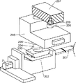
Fig. 3 is a schematic perspective view of a first motor according to the present invention.
Fig. 4 is a schematic perspective view of the primary stretching mechanism of the present invention.
Fig. 5 is a schematic perspective view of the stamped column according to the present invention.
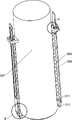
Fig. 6 is an enlarged schematic view of the structure of the stamped column of the invention.
Fig. 7 is an enlarged schematic view of the structure of the stamped column of the invention.
Fig. 8 is a perspective view of the outer side of the second sliding plate according to the present invention.
Fig. 9 is a schematic perspective view of the clamping mechanism of the present invention.
Fig. 10 is an enlarged view of the structure of the clamping mechanism of the present invention.
Fig. 11 is a schematic perspective view of the ejection mechanism of the present invention.
Fig. 12 is a schematic perspective view of the sliding material receiving plate according to the present invention.
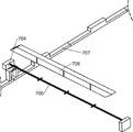
Fig. 13 is a schematic perspective view of a second carriage according to the present invention.
Fig. 14 is an exploded view of the structure at the slide ramp of the present invention.
In the above drawings: 1_ bottom support frame, 101_ middle support frame, 102_ top mount, 103_ press die, 104_ first fixing plate, 2_ motor number one, 201_ first lead screw, 202_ first slide block, 203_ second slide block, 204_ first slide bar, 205_ first spring, 206_ L-shaped slide block, 207_ first slide plate, 208_ third slide block, 209_ second spring, 3_ first air cylinder, 301_ first lifting plate, 302_ second air cylinder, 303_ first guide bar, 304_ second guide bar, 305_ ring cutter, 306_ second lifting plate, 307_ press-formed post, 308_ second slide bar, 309_ third spring, 310_ first fixing block, 311_ second slide block, 312_ fourth spring, 313_ first fixing frame, 314_ fixing inclined block, 315_ second fixing block, 3151_ first rotating shaft, 3152_ fourth sliding block, 3153_ stopper rod, 316_ fifth spring, 4_ first fixed slide, 401_ first fixed bar, 4011_ second fixed slide, 402_ second motor, 403_ second lead screw, 404_ first bushing, 405_ third sliding plate, 406_ second fixed frame, 407_ first gear, 408_ second rotating shaft, 409_ first rotating plate, 410_ first connecting rod, 411_ second connecting rod, 412_ fifth sliding block, 413_ arc clamping plate, 414_ first carriage, 415_ third guide rod, 416_ sixth spring, 417_ third fixed block, 5_ third cylinder, 501_ fourth guide rod, 502_ third lifting plate, 503_ moving push rod, 6_ third motor, 601_ third lead screw, 602_ sliding material plate, 603_ fifth guide rod, 7_ fourth cylinder, 701_ second carriage, 702_ magnet, 703_ straight cutter, 704_ fourth fixed block, 705_ first connecting frame, 706_ slide ramp, 707_ lifter.
Detailed Description
The present invention will be further described with reference to the following examples.
The following examples are intended to illustrate the invention but are not intended to limit the scope of the invention. The conditions in the embodiments can be further adjusted according to specific conditions, and simple modifications of the method of the present invention based on the concept of the present invention are within the scope of the claimed invention.
Example 1
A special die device for stretching and forming a cylindrical battery steel shell comprises a bottom support frame 1, a middle support frame 101, a top fixing frame 102, a stamping die 103, a first fixing plate 104, a primary stretching mechanism, an ejection mechanism, a clamping mechanism and a secondary stretching mechanism, wherein a material receiving frame can be placed in the bottom support frame 1 for collecting the manufactured battery steel shell, the top of the bottom support frame 1 is provided with the middle support frame 101, the top of the middle support frame 101 is provided with the top fixing frame 102, the top side of the bottom support frame 1 is fixedly provided with the first fixing plate 104, a plurality of through holes are formed in the first fixing plate 104, the top of the first fixing plate 104 is provided with the stamping die 103, four rows of through holes are formed in the stamping die 103, the tops of the through holes in the front two rows of the stamping die 103 are provided with grooves for placing steel sheets, and two rectangular grooves are symmetrically formed in the front and back of the through holes in the back two rows of the stamping die 103, the primary stretching mechanism is arranged in the middle supporting frame 101 and used for taking materials from a steel plate and primarily stretching the materials, the ejection mechanism is arranged in the bottom supporting frame 1 and used for ejecting a steel shell at the front end of the stamping die 103, the clamping mechanism is arranged in the middle supporting frame 101 and used for clamping and moving the steel shell, the secondary stretching mechanism is arranged in the middle supporting frame 101 and used for secondarily stretching and forming the steel shell.
When the steel shell primary stamping device works, a steel plate is placed at the top of a stamping die 103 in a middle support frame 101, then a primary stretching mechanism is started, the primary stretching mechanism can intercept a plurality of cylindrical steel sheets from the steel plate, then the primary stretching mechanism stretches the steel sheets for the first time, then when the primary stretching mechanism resets, an ejection mechanism is started, the ejection mechanism ejects a steel shell in the stamping die 103, when the steel shell is ejected out of the stamping die 103, a clamping mechanism is started, the clamping mechanism clamps the steel shell and conveys the steel shell to the rear half section of the stamping die 103 backwards, then the clamping mechanism releases the steel shell, when in primary stamping, the top of the steel shell can outwards generate an annular edge, the steel shell is clamped in a through hole in the rear half section of the stamping die 103 under the action of the annular edge, when the clamping mechanism resets, a secondary stretching mechanism is started, the primary stamped steel shell can be stretched again by the secondary stretching mechanism, after the steel shell is stretched and formed by the secondary stretching mechanism, the secondary stretching mechanism can clamp the steel shell out, and then the steel shell is manually taken out, so that the function of stretching and forming the steel shell of the cylindrical battery is realized.
Example 2
On the basis of embodiment 1, as shown in fig. 4, the primary stretching mechanism includes a first cylinder 3, a first lifting plate 301, a second cylinder 302, a first guide rod 303, a second guide rod 304, a circular cutter 305, a second lifting plate 306 and a stamping column 307, the first cylinder 3 is installed at both ends of the middle support frame 101, the output shaft of the first cylinder 3 is arranged upward, the first lifting plate 301 is connected to the output shafts of the two first cylinders 3, the first cylinder 3 drives the first lifting plate 301 to move up and down, the second guide rod 304 is installed at both ends of the middle support frame 101, the second lifting plate 306 is connected to the top ends of the two second guide rods 304 in a sliding manner, the second lifting plate 306 slides up and down along the two second guide rods 304, the second cylinder 302 is installed in the top fixing frame 102, the output shaft of the second cylinder 302 is arranged downward, an output shaft of the second air cylinder 302 is connected to the second lifting plate 306, the second air cylinder 302 drives the second lifting plate 306 to move up and down, the two sides of the first lifting plate 301 are fixed with a first guide rod 303, the top of the first guide rod 303 penetrates through the second lifting plate 306, the two first guide rods 303 are slidably connected with the second lifting plate 306, a plurality of annular cutters 305 are fixed on the rectangular array at the bottom of the first lifting plate 301, the annular cutters 305 can cut steel sheets with a certain size on the steel sheets, a plurality of stamping columns 307 are fixed on the rectangular array at the bottom of the second lifting plate 306, the stamping columns 307 can penetrate through the interior of the annular cutters 305, and the stamping columns 307 are used for stamping the steel sheets into steel shells.
When a steel plate is placed on the top of a stamping die 103, a first air cylinder 3 is started, the first air cylinder 3 drives a first lifting plate 301 to descend, the first lifting plate 301 descends to drive a first guide rod 303 and annular cutters 305 to descend, each annular cutter 305 cuts a cylindrical steel sheet from the steel plate, the first air cylinder 3 is closed, the cylindrical steel sheet falls into the stamping die 103, a second air cylinder 302 is started, the second air cylinder 302 pushes a second lifting plate 306 downwards, the second lifting plate 306 slides downwards along the first guide rod 303 and the second guide rod 304, a stamping forming column 307 descends, the steel sheet is pressed downwards to form a steel shell when the stamping forming column 307 is contacted with the steel sheet, the steel plate is stretched and formed when the second lifting plate 306 is contacted with the first lifting plate 301, the second air cylinder 302 drives the second lifting plate 306 to ascend, the second lifting plate 306 drives the stamping forming column 307 to ascend, starting cylinder 3 simultaneously and driving first lifter plate 301 and rising, first lifter plate 301 drives annular cutter 305, first guide bar 303 and rises, and when first lifter plate 301 resets the back, closing cylinder 3, when second lifter plate 306 resets the back, closing cylinder 302 No. two, realize the function of preliminary tensile box hat.
As shown in fig. 11, the ejection mechanism includes a third air cylinder 5, fourth guide rods 501, a third lifting plate 502 and a movable push rod 503, the third air cylinder 5 is installed in the bottom support frame 1, an output shaft of the third air cylinder 5 faces upward, the fourth guide rods 501 are fixed on two side walls of the bottom support frame 1, the third lifting plate 502 is connected to the two fourth guide rods 501 in a sliding manner, an output shaft of the third air cylinder 5 is connected to the third lifting plate 502, the third air cylinder 5 controls the third lifting plate 502 to slide up and down along the two fourth guide rods 501, a plurality of movable push rods 503 are fixed in a rectangular array on the top of the third lifting plate 502, the movable push rods 503 are just aligned with through holes in the top stamping die 103 and the first fixing plate 104, and the movable push rods 503 can pass through the through holes in the stamping die 103 and the first fixing plate 104.
After the second lifting plate 306 is reset, the third cylinder 5 is started, the third cylinder 5 pushes the third lifting plate 502 upwards, the third lifting plate 502 drives the movable push rod 503 to ascend, the movable push rod 503 pushes the steel shell in the stamping die 103 upwards, after the steel shell is clamped by the clamping mechanism, the third cylinder 5 drives the third lifting plate 502 to descend and simultaneously drives the movable push rod 503 to descend, and after the third lifting plate 502 is reset, the third cylinder 5 is closed, so that the function of pushing the steel shell out of the stamping die plate is realized.
As shown in fig. 9-10, the clamping mechanism includes a first fixed slide 4, a first fixed rod 401, a second fixed slide 4011, a second motor 402, a second lead screw 403, a first bushing 404, a third sliding plate 405, a second fixed frame 406, a first gear 407, a second rotating shaft 408, a first rotating plate 409, a first connecting rod 410, a second connecting rod 411, a fifth sliding block 412, an arc-shaped clamping plate 413, a first carriage 414, a third guiding rod 415, a sixth spring 416, and a third fixed block 417, four first fixed rods 401 are fixed in the middle supporting frame 101, the first fixed rods 401 are vertically arranged, one second fixed slide 4011 is fixed between the two first fixed rods 401 at the left and right sides, the second fixed slide 4011 is arranged in the front-back direction, a second motor 402 is installed at the bottom of the front wall of the two first fixed rods 401 at the front side, the output shaft of the second motor 402 passes through the first fixed rod 401 at the front side and is rotatably connected thereto, a second screw 403 is connected to an output shaft of each second motor 402, the other end of each second screw 403 is rotatably connected to a first fixing rod 401 at the rear side, the second motor 402 drives the second screw 403 to rotate, a first shaft sleeve 404 is sleeved on each second screw 403, the first shaft sleeve 404 is slidably connected with a second fixing slideway 4011, when the second screws 403 rotate, the first shaft sleeve 404 slides back and forth along the second fixing slideway 4011, a third sliding plate 405 is fixed at the bottom of each first shaft sleeve 404, the third sliding plate 405 slides back and forth along the first shaft sleeve 404, a second fixing frame 406 is fixed at both ends of each third sliding plate 405, the second fixing frame 406 moves along the third sliding plate 405, teeth are arranged in each second fixing frame 406, but the positions of the teeth change according to the positions of the second fixing frames 406, two first fixing slideways 4 are symmetrically installed at left and right in the middle support frame 101, a first sliding frame 414 is connected in two first fixed sliding ways 4 in a sliding manner, the first sliding frame 414 slides back and forth in the two first fixed sliding ways 4, the top of the first sliding frame 414 is connected with four second rotating shafts 408 in a bilateral-symmetric manner, the top of each second rotating shaft 408 is fixed with a first gear 407, each first gear 407 is positioned in a second fixed frame 406, teeth in each second fixed frame 406 are engaged with the corresponding first gear 407, the bottom of each second rotating shaft 408 is fixed with a first rotating disc 409, the first gear 407 drives the first rotating disc 409 to rotate through the second rotating shaft 408, the bottom of each first rotating disc 409 is connected with two first connecting rods 410 in a rotating manner, when the first rotating disc 409 rotates, the corresponding two first connecting rods 410 are inwardly closed or outwardly separated, a rectangular array is provided with a plurality of rectangular through holes in the first sliding frame 414, four fifth sliding blocks 412 are connected in each rectangular through hole in a sliding manner, two arc-shaped clamping plates 413 are connected between the fifth sliding blocks 412 in the same rectangular through hole, the two arc-shaped clamping plates 413 are symmetrically arranged in the front and back direction, the steel shell can be clamped just when the two arc-shaped clamping plates 413 are close to each other, a second connecting rod 411 is connected between the fifth sliding blocks 412 in the two adjacent rectangular through holes, the second connecting rod 411 is connected with a first sliding frame 414 in a sliding manner, the other end of each first connecting rod 410 is connected to one second connecting rod 411, the first connecting rod 410 drives the corresponding second connecting rod 411 to move back and forth, a plurality of third fixed blocks 417 are fixed at the top of the first sliding frame 414, a third guide rod 415 is fixed on each third fixed block 417, the third guide rods 415 play a guiding role, the other end of each third guide rod 415 is connected in one second connecting rod 411 in a sliding manner, the second connecting rods 411 slide along the third guide bars 415, and a sixth spring 416 is connected between each second connecting rod 411 and the corresponding third fixing block 417, and the sixth spring 416 is used to restore the second connecting rods 411.
When the steel shell is pushed out from the stamping die plate by moving the push rod 503, the second motor 402 is started, the second motor 402 drives the second lead screw 403 to rotate, the second lead screw 403 rotates to drive the first bushing 404 to slide backwards along the second fixed slideway 4011, the third sliding plate 405 and the second fixed frame 406 slide backwards along with the second lead screw, teeth are arranged in each second fixed frame 406, the teeth of the second fixed frame 406 on the right front side are arranged on the inner left wall, the teeth of the second fixed frame 406 on the left front side are arranged on the inner right wall, the teeth of the second fixed frame 406 on the left rear side are arranged on the inner left wall, the teeth of the second fixed frame 406 on the right rear side are arranged on the inner right wall, when the second fixed frame 406 on the right front side moves backwards, the first gear 407 on the right front side rotates clockwise to drive the second rotating shaft 408 and the first rotating disk 409 to rotate clockwise, clockwise rotation of the first rotating disc 409 pulls the two first connecting rods 410 inwards, the two first connecting rods 410 pulls the two second connecting rods 411 inwards, inward movement of the two second connecting rods 411 causes the fifth sliding blocks 412 on both sides to slide inwards, the inward sliding of the fifth sliding blocks 412 drives the arc-shaped clamping plates 413 to slide inwards, when the inner front wall of the second fixed frame 406 on the right front side contacts with the first gear 407, the first gear 407 does not rotate any more, at this time, the arc-shaped clamping plates 413 clamp the steel shell, similarly, the first gears 407 on the left front side, the left rear side and the right rear side all contact with the corresponding inner front wall of the second fixed frame 406 and cannot rotate, at this time, all the arc-shaped clamping plates 413 clamp the steel shell under the action of the four first gears 407, at this time, the second lead screw 403 still rotates, the first shaft sleeve 404 continues to drive the third sliding plate 405 and the second fixed frame 406 to move backwards, the second fixed frame 406 drives the first sliding frame 414 to slide backwards along the two first fixed slideways 4 on the two sides through the first gear 407 and the second rotating shaft 408, and simultaneously drives all the steel shells to move backwards, when the first bushing 404 moves to the rearmost side of the second lead screw 403, all the steel shells move backwards to the rear half section of the stamping die 103, at this time, the second motor 402 rotates in reverse, the second motor 402 drives the second lead screw 403 to rotate in reverse, the reverse rotation of the second lead screw 403 causes the first bushing 404 to slide forwards along the second fixed slideway 4011, the first bushing 404 drives the third sliding plate 405 and the second fixed frame 406 to move forwards, when the second fixed frame 406 on the right front side moves forwards, the first gear 407 on the right front side rotates counterclockwise, the second rotating shaft 408 and the first rotating disk 409 rotate counterclockwise, the first rotating disk 409 rotates counterclockwise to pull the two first connecting rods 410 outwards, the two first connecting rods 410 push the two second connecting rods 411 outwards, the two second connecting rods 411 move outwards to make the fifth sliding blocks 412 on the two sides slide outwards, the fifth sliding blocks 412 slide outwards to drive the arc-shaped clamping plates 413 to slide outwards, when the inner back wall of the second fixed frame 406 on the right front side contacts with the first gear 407, the first gear 407 does not rotate any more, at this time, the arc-shaped clamping plates 413 already release the steel shell, similarly, the first gears 407 on the left front side, the left back side and the right back side all contact with the corresponding inner back wall of the second fixed frame 406 and cannot rotate, at this time, all the arc-shaped clamping plates 413 release the steel shell under the action of the four first gears 407, at this time, the steel shell descends and falls into the through hole on the back half section of the stamping die 103, the second lead screw 403 continues to rotate reversely, so that the first shaft sleeve 404 continues to drive the third sliding plate 405 and the second fixed frame 406 to move forwards, the second fixed frame 406 drives the first sliding frame 414 to slide forward along the two first fixed slideways 4 on the two sides through the first gear 407 and the second rotating shaft 408, and after the first sliding frame 414 is reset, the second motor 402 is turned off, so that the functions of clamping and moving the steel shell are realized.
As shown in fig. 4-7, the secondary stretching mechanism includes a second sliding rod 308, a third spring 309, a first fixing block 310, a second sliding plate 311, a fourth spring 312 and a first fixing frame 313, the top of the front and back sides of the two rows of stamping columns 307 behind the second lifting plate 306 is fixed with the first fixing frame 313, the first fixing frame 313 on both sides of each stamping column 307 is provided with a rectangular through hole, each first fixing frame 313 is connected with the second sliding rod 308 in a sliding manner, the second sliding rod 308 can slide up and down, the bottom of each second sliding rod 308 is fixed with the first fixing block 310, the first fixing block 310 can move with the second sliding rod 308, a third spring 309 is connected between each first fixing block 310 and the first fixing frame 313 on the same side, each first fixing frame 313 is connected with the second sliding plate 311 in a sliding manner, the second sliding plate 311 can slide back and forth along the first fixing frame 313, the second sliding plate 311 can also slide up and down along the first fixed frame 313, the bottom of the second sliding plate 311 is slidably connected with the first fixed block 310, and two fourth springs 312 are connected between the bottom of the second sliding plate 311 and the first fixed block 310.
When the primarily stretched steel shell falls into the rear section of the stamping die 103, the second air cylinder 302 is started, the second air cylinder 302 pushes the second lifting plate 306 downwards, the second lifting plate 306 drives the stamping forming column 307, the second sliding rod 308, the third spring 309, the first fixed block 310, the second sliding plate 311, the fourth spring 312 and the first fixed frame 313 to move downwards, the stamping forming column 307 descends to stretch and form the primarily stretched steel shell again, the second sliding plate 311 contacts with the edge of the steel shell in the descending process, the bottom of the second sliding plate 311 is pressed outwards into the first fixed block 310 by the edge of the top wall of the steel shell, after the second sliding plate 311 is separated from the steel shell, the second sliding plate 311 is reset inwards under the action of the fourth spring 312, and when the first fixed block 310 contacts with the stamping die 103, the second sliding rod 308, the first fixed block 310, the second sliding plate 311 and the fourth spring 312 do not descend again, meanwhile, the third spring 309 is compressed, after the steel shell is formed, the second cylinder 302 controls the second lifting plate 306 to ascend, the second lifting plate 306 drives the stamping forming column 307 and the first fixing frame 313 to move upwards, the third spring 309 gradually resets, after the third spring 309 resets, the stamping forming column 307, the second sliding rod 308, the third spring 309, the first fixing block 310, the second sliding plate 311 and the fourth spring 312 move upwards, the two second sliding plates 311 on the two sides of the stamping forming column 307 can lift the steel shell from the two sides of the top of the steel shell, then the steel shell is taken out manually, after the second lifting plate 306 resets, the second cylinder 302 is closed, and the function of secondary stretching and forming of the steel shell is achieved.
Example 3
On the basis of the embodiment 2, as shown in fig. 2-3, the stamping die further includes a first motor 2, a first lead screw 201, a first sliding block 202, a second sliding block 203, a first sliding rod 204, a first spring 205, an L-shaped sliding block 206, a first sliding plate 207, a third sliding block 208 and a second spring 209, the first motor 2 is installed on both sides of the stamping die 103, an output shaft of the first motor 2 is arranged forward, the output shaft of each first motor 2 is connected with a first lead screw 201, the first motor 2 drives the first lead screw 201 to rotate, the front end of each first lead screw 201 is rotatably connected to the stamping die 103, the left and right sides of the middle support frame 101 are slidably connected with a first sliding block 202, the top of the first sliding block 202 is sleeved on the first lead screw 201, when the first lead screw 201 rotates, the first sliding block 202 slides back and forth along the middle support frame 101, a second sliding block 203 is connected to the top of each first sliding block 202 in a sliding manner, the second sliding block 203 can slide back and forth on the top of the first sliding block 202, a first sliding rod 204 is fixed to the middle of the top wall of each second sliding block 203, the first sliding rod 204 can move along with the second sliding block 203, an L-shaped sliding block 206 is connected to each first sliding rod 204 in a sliding manner, each L-shaped sliding block 206 is connected with the middle supporting frame 101 in a sliding manner, the L-shaped sliding block 206 slides back and forth along the middle supporting frame 101 along with the first sliding rod 204, a first spring 205 is connected between each L-shaped sliding block 206 and the corresponding second sliding block 203, a first sliding plate 207 is fixed to the top of each first sliding rod 204, the first sliding plate 207 can move back and forth along with the first sliding rod 204, a third sliding block 208 is connected to the middle of the bottom surface of each first sliding plate 207 in a sliding manner, the third sliding blocks 208 and the L-shaped sliding blocks 206 have enough clearance for the steel plate to pass through, and a second spring 209 is connected between each third sliding block 208 and the corresponding first sliding plate 207.
The forward rotation of the two first motors 2 can enable the first lead screw 201 to rotate forward, and the first sliding block 202 can move forward; when the first motor 2 rotates reversely, the first lead screw 201 rotates reversely, the first sliding block 202 moves backwards, when feeding is performed, the two first motors 2 are started first, the two first motors 2 drive the two first lead screws 201 to rotate forwardly, the two first lead screws 201 rotate forwardly, the two first sliding blocks 202 slide forwardly, when the two first sliding blocks 202 slide forwardly, the second sliding block 203 slides on the top of the first sliding block 202 first, when the second sliding block 203 contacts with the inclined surface on the top of the first sliding block 202, the second sliding block 203 rises along the inclined surface on the top of the first sliding block 202, the second sliding block 203 rises to drive the first sliding rod 204 and the first sliding plate 207 to rise, when the first sliding plate 207 rises to drive the third sliding block 208 and the second spring 209 to rise, when the rear vertical wall of the first sliding block 202 contacts with the second sliding block 203, the first sliding block 202 drives the second sliding block 203, the second sliding block 203 and the second sliding block 203, The first sliding rod 204, the first spring 205, the L-shaped sliding block 206, the first sliding plate 207, the third sliding block 208 and the second spring 209 slide forward, when the first sliding block 202 moves to the forefront, a worker puts one end of the steel plate between the L-shaped sliding block 206 and the third sliding block 208, then the two first motors 2 rotate reversely, the two first lead screws 201 also rotate reversely, the two first sliding blocks 202 slide backward, the two second sliding blocks 203 move downward along the inclined planes on the corresponding first sliding blocks 202, and simultaneously, the two first sliding rods 204 and the two first sliding plates 207 are driven to descend, the two first sliding plates 207 descend to drive the two third sliding blocks 208 and the second spring 209 to descend, the two third sliding blocks 208 are matched with the two L-shaped sliding blocks 206 under the action of the two second springs 209 to clamp the two ends of the steel plate, when the front vertical sliding block wall of the first sliding block 202 is contacted with the corresponding second sliding blocks 203, each first sliding block 202 drives the second sliding block 203, the first sliding rod 204, the first spring 205, the L-shaped sliding block 206, the first sliding plate 207, the third sliding block 208 and the second spring 209 on the same side to slide backwards, and simultaneously drives the steel plate to move backwards, when the first sliding block 202 is reset, the first motor 2 is turned off, and at the moment, the steel plate moves to a position to be processed; after the battery steel shell is machined, the two first motors 2 are started again to drive the first lead screw 201 to rotate forwards to enable the first sliding block 202 to move forwards, the first sliding block 202 drives the L-shaped sliding block 206, the first sliding plate 207 and the third sliding block 208 to move forwards to the foremost end of the first lead screw 201 through the second sliding block 203 and the first sliding rod 204 to clamp a steel plate, then the first motors 2 rotate backwards to enable the L-shaped sliding block 206, the first sliding block 207 and the third sliding block 208 to move backwards and pull the steel plate backwards, and when the first sliding block 202 resets, the first motors 2 are closed to achieve the function of automatically conveying the steel plate backwards.
As shown in fig. 6-8 and 13, the cutting tool further comprises a fixed inclined block 314, a second fixed block 315, a first rotating shaft 3151, a fourth sliding block 3152, a limiting rod 3153, a fifth spring 316, a fourth cylinder 7, a second sliding frame 701, a magnet 702 and a straight cutter 703, wherein two fixed inclined blocks 314 are fixed on the top of each first fixed frame 313, the inclined surface of each fixed inclined block 314 faces upward, two second fixed blocks 315 are fixed on one side of the top of each second sliding plate 311 close to the second sliding rod 308, an inclined surface is arranged at the bottom of the inner side of each second fixed block 315, one end of each second fixed block 315 close to the second sliding rod 308 is rotatably connected with one first rotating shaft 3151, the first rotating shaft 3151 can move along the inclined surface of the fixed inclined block 314, a slide way is arranged on the outer side of each second sliding plate 311, a fourth sliding block 3152 is slidably connected on the outer side of each second sliding plate 311, two limiting rods 3153 are fixed on the outer wall of each fourth sliding block 3152, the limiting rods 3153 are connected with the first fixing frame 313 in a sliding mode, the limiting rods 3153 can slide back and forth in the first fixing frame 313, two fifth springs 316 are connected between each fourth sliding block 3152 and the first fixing frame 313, each fifth spring 316 is sleeved on one limiting rod 3153, two four cylinders 7 are symmetrically installed in the middle supporting frame 101 in a left-right mode, the output shafts of the four cylinders 7 are arranged forwards, a second sliding frame 701 is connected in the middle supporting frame 101 in a sliding mode, the output shafts of the four cylinders 7 are connected to the second sliding frame 701, the four cylinders 7 can push the second sliding frame 701 to slide back and forth, a plurality of magnets 702 are installed in the second sliding frame 701, a straight cutter 703 is fixed to the front end of the bottom face of the second sliding frame 701, and the cutting edge of the straight cutter 703 faces forwards.
After the battery steel shell is taken out of the stamping die 103 by the second sliding plate 311 on both sides of the stamping forming column 307 on the rear side of the second lifting plate 306, when the excess waste material on the top of the battery steel shell rises to the upper side of the straight cutter 703 along with the stamping forming column 307, the second cylinder 302 is closed, the two fourth cylinders 7 are started, the two fourth cylinders 7 push the second sliding frame 701 to slide forward, the second sliding frame 701 drives the magnet 702 and the straight cutter 703 to move forward, when the waste material on the top of the battery steel shell is cut off by the straight cutter 703, the battery steel shell falls downward, the fallen battery steel shell is manually collected out, the second sliding frame 701 just drives the magnet 702 to move to the top of the waste material of the battery shell, at this time, the magnet 702 just sucks the waste material of the battery shell, then the fourth cylinder 7 is closed, the second cylinder 302 is started, the second cylinder 302 drives the second lifting plate 306 to rise, the stamping forming column 307 on the rear side of the second lifting plate 306 also rises along with it, the first fixing frame 313 and the fixing inclined block 314 at both sides of the press-formed column 307 are also lifted, the fourth sliding block 3152, the stopper 3153 and the fifth spring 316 are also lifted, at this time, the second sliding frame 701 and the magnet 702 are just clamped at the top of the battery case waste, the second sliding plate 311 and the second sliding bar 308 are clamped and cannot be lifted, at this time, the third spring 309 is stretched, the second fixing block 315 and the first rotating shaft 3151 at the inner side of the second sliding plate 311 are in contact with the fixing inclined block 314, when the first rotating shaft 3151 slides outwards along the fixing inclined block 314, the second sliding plate 311 is also moved outwards, the fourth spring 312 and the fifth spring 316 are both compressed, when the bottom of the second sliding plate 311 moves to both sides of the battery case waste, under the action of the third spring 309, the second sliding plate 311, the second fixing block 315, the first rotating shaft 3151 and the second sliding bar 308 are rapidly moved upwards to be restored, meanwhile, the second sliding plate 311 is moved inward under the action of the fourth spring 312 and the fifth spring 316 to return, the waste materials of the battery case are adsorbed by the magnet 702 on the second sliding frame 701, after the second lifting plate 306 is returned, the second cylinder 302 is closed, the two cylinders 7 are started, the two cylinders 7 drive the second sliding frame 701 to slide backward, the second sliding frame 701 drives the straight cutting knife 703, the magnet 702 and the waste materials of the battery case to move backward, and after the second sliding frame 701 is returned, the cylinders 7 are closed, so that the function of cutting the waste materials on the top of the battery case is realized.
As shown in fig. 13 to 14, the lifting device further includes fourth fixed blocks 704, first connecting frames 705, sliding inclined blocks 706 and lifting rods 707, four fourth fixed blocks 704 are symmetrically fixed on the second sliding frame 701 in the left-right direction, a first connecting frame 705 is fixed between every two fourth fixed blocks 704, three cross rods are arranged on the first connecting frame 705, a sliding inclined block 706 is slidably connected to each first connecting frame 705, the sliding inclined blocks 706 can only slide up and down under the action of the cross rods of the first connecting frame 705, a lifting rod 707 is further slidably connected in the middle support frame 101, and the lifting rod 707 can only slide up and down along a vertical slide of the middle support frame 101.
When the second sliding frame 701 is pushed forwards by the two fourth cylinders 7, the second sliding frame 701 drives the magnet 702, the straight cutter 703, the fourth fixed block 704, the first connecting frame 705 and the sliding inclined block 706 to move forwards, the waste of the battery case on the magnet 702 also moves forwards, the front end of the sliding inclined block 706 is inclined upwards, two inverted U-shaped frames are symmetrically arranged on the lifting rod 707 in the left-right direction, the two sliding inclined blocks 706 on the second sliding frame 701 move forwards and push the lifting rod 707 upwards through the two inverted U-shaped frames, when the waste of the battery case continues to move forwards, the lifting rod 707 blocks the waste of the battery case, the waste of the battery case is separated from the two magnets 702 and falls downwards onto the bottom surface of the rear side of the middle support frame 101, when the two sliding inclined blocks 706 leave from the two inverted U-shaped frames on the lifting rod 707, the lifting rod 707 slides downwards, and when the second sliding frame 701 is pulled backwards by the two fourth cylinders 7, the two sliding inclined blocks 706 on the second sliding frame 701 slide upwards along the two inverted U-shaped frames on the lifting rod 707, and the sliding inclined blocks 706 pass through the tops of the two inverted U-shaped frames on the lifting rod 707, so that the lifting rod 707 does not block the battery case waste between the magnets 702, and the function of automatically taking out the waste between the magnets 702 is realized.
As shown in fig. 12, the stamping die further includes a third motor 6, a third lead screw 601, a sliding material receiving plate 602 and a fifth guide rod 603, the third motor 6 is mounted on the first fixing plate 104, an output shaft of the third motor 6 is connected with the third lead screw 601, the third motor 6 drives the third lead screw 601 to rotate, the other end of the third lead screw 601 is rotatably connected to the rear end of the middle support frame 101, the fifth guide rod 603 is fixed at the bottom of the right side of the middle support frame 101, the bottom of the middle support frame 101 is slidably connected with the sliding material receiving plate 602, the initial position of the sliding material receiving plate 602 is located below the stamping die 103, the left end of the sliding material receiving plate 602 is sleeved on the third lead screw 601, the right side of the sliding material receiving plate 602 is sleeved on the fifth guide rod 603, and the sliding material receiving plate 602 can slide back and forth along the third lead screw 601 and the fifth guide rod 603.
When the battery steel shell is stamped downwards by the stamping forming column 307, the sliding material receiving plate 602 is located below the stamping die 103, the sliding material receiving plate 602 plays a certain supporting role, after the battery steel shell is stamped and formed, the third motor 6 is started, the third motor 6 drives the third screw rod 601 to rotate, the third screw rod 601 rotates to enable the sliding material receiving plate 602 to move backwards along the fifth guide rod 603, the sliding material receiving plate 602 moves backwards to push out the waste material of the battery shell in the middle support frame 101 backwards, the formed battery steel shell falls downwards from the stamping die 103, then the third motor 6 rotates backwards, the third screw rod 601 rotates backwards, the sliding material receiving plate 602 moves forwards along the fifth guide rod 603 to reset, and after the sliding material receiving plate 602 resets, the third motor 6 is turned off to realize the functions of supporting the battery steel shell and pushing out the waste material of the battery shell backwards.
Although embodiments of the present invention have been shown and described, it will be appreciated by those skilled in the art that various changes, modifications, substitutions and alterations can be made in these embodiments without departing from the principles and spirit of the invention, the scope of which is defined in the appended claims and their equivalents.
Claims (7)
1. The utility model provides a special die device of cylinder battery box hat stretch forming, characterized by: the steel plate drawing device comprises a bottom supporting frame (1), a middle supporting frame (101), a top fixing frame (102), a stamping die (103), a first fixing plate (104), a primary drawing mechanism, an ejection mechanism, a clamping mechanism and a secondary drawing mechanism, wherein the middle supporting frame (101) is installed at the top of the bottom supporting frame (1), the top fixing frame (102) is installed at the top of the middle supporting frame (101), the first fixing plate (104) is fixed at the top side in the bottom supporting frame (1), the stamping die (103) is installed at the top of the first fixing plate (104), the primary drawing mechanism is installed in the middle supporting frame (101), the primary drawing mechanism is used for taking a steel plate and primarily drawing, the ejection mechanism is installed in the bottom supporting frame (1), the ejection mechanism is used for ejecting a steel shell at the front end of the stamping die (103), the clamping mechanism is installed in the middle supporting frame (101), the clamping mechanism is used for clamping and moving the steel shell, the secondary stretching mechanism is arranged in the middle supporting frame (101), and the secondary stretching mechanism is used for secondarily stretching and forming the steel shell;
The primary stretching mechanism comprises a first cylinder (3), a first lifting plate (301), a second cylinder (302), a first guide rod (303), a second guide rod (304), an annular cutter (305), a second lifting plate (306) and a stamping forming column (307), wherein the first cylinder (3) is arranged at each of two ends of a middle supporting frame (101), the first lifting plate (301) is connected to an output shaft of each of the two first cylinders (3) together, the second guide rod (304) is arranged at each of two ends of the middle supporting frame (101), the second lifting plate (306) is connected to the top ends of the two second guide rods (304) together in a sliding manner, the second cylinder (302) is arranged in a top fixing frame (102), an output shaft of the second cylinder (302) is connected to the second lifting plate (306), the first guide rods (303) are fixed on two sides of the first lifting plate (301), two ends of the rear side of the second lifting plate (306) are sleeved on the two first guide rods (303), the second lifting plate (306) is connected with the first guide rods (303) in a sliding mode, a plurality of annular cutters (305) are fixed to the bottom of the first lifting plate (301) in a rectangular array mode, and a plurality of stamping forming columns (307) are fixed to the bottom of the second lifting plate (306) in a rectangular array mode;
The secondary stretching mechanism comprises second sliding rods (308), third springs (309), first fixing blocks (310), second sliding plates (311), fourth springs (312) and first fixing frames (313), wherein the top parts of the front side and the rear side of two rows of stamping forming columns (307) behind the second lifting plate (306) are respectively fixed with one first fixing frame (313), each first fixing frame (313) is internally and slidably connected with one second sliding rod (308), the bottom part of each second sliding rod (308) is respectively fixed with one first fixing block (310), a third spring (309) is respectively connected between each first fixing block (310) and the first fixing frame (313) on the same side, each first fixing frame (313) is internally and slidably connected with one second sliding plate (311), the bottom part of each second sliding plate (311) is slidably connected with the first fixing block (310), and two fourth springs (312) are connected between the bottom of the second sliding plate (311) and the first fixed block (310).
2. The special female die device for stretching and forming the cylindrical battery steel shell according to claim 1, which is characterized in that: the ejection mechanism comprises a third cylinder (5), fourth guide rods (501), a third lifting plate (502) and movable push rods (503), the third cylinder (5) is installed in the bottom support frame (1), the two side walls of the bottom support frame (1) are respectively fixed with the fourth guide rods (501), the two fourth guide rods (501) are jointly connected with the third lifting plate (502) in a sliding mode, output shafts of the third cylinder (5) are connected onto the third lifting plate (502), and the rectangular array at the top of the third lifting plate (502) is fixed with the movable push rods (503).
3. The special female die device for stretching and forming the cylindrical battery steel shell as claimed in claim 2, which is characterized in that: the clamping mechanism comprises a first fixed slideway (4), first fixed rods (401), a second fixed slideway (4011), a second motor (402), a second screw rod (403), a first shaft sleeve (404), a third sliding plate (405), a second fixed frame (406), a first gear (407), a second rotating shaft (408), a first rotating disc (409), a first connecting rod (410), a second connecting rod (411), a fifth sliding block (412), an arc-shaped clamping plate (413), a first sliding frame (414), a third guide rod (415), a sixth spring (416) and a third fixed block (417), wherein four first fixed rods (401) are fixed in a middle supporting frame (101), a second fixed slideway (4011) is fixed between the two first fixed rods (401) at the left side and the right side, the bottom parts of the front walls of the two first fixed rods (401) at the front side are respectively provided with a second motor (402), a second screw rod (403) is connected to an output shaft of each second motor (402), the other end of each second screw rod (403) is rotatably connected to a first fixing rod (401) at the rear side, a first shaft sleeve (404) is sleeved on each second screw rod (403), the first shaft sleeve (404) is slidably connected with a second fixing slide way (4011), a third sliding plate (405) is fixed at the bottom of each first shaft sleeve (404), a second fixing frame (406) is fixed at each of two ends of each third sliding plate (405), two first fixing slide ways (4) are symmetrically installed in the middle support frame (101) in the left and right direction, a first sliding frame (414) is slidably connected in the two first fixing slide ways (4) together, four second rotating shafts (408) are rotatably connected in the left and right direction at the top of the first sliding frame (414), a first gear (407) is fixed at the top of each second rotating shaft (408), a first rotating disc (409) is fixed at the bottom of each second rotating shaft (408), two first connecting rods (410) are rotatably connected at the bottom of each first rotating disc (409), a plurality of rectangular through holes are formed in the first sliding frame (414) in a rectangular array, four fifth sliding blocks (412) are slidably connected in each rectangular through hole, two arc-shaped clamping plates (413) are connected between the fifth sliding blocks (412) in the same rectangular through hole, the two arc-shaped clamping plates (413) are symmetrically arranged in the front and back direction, a second connecting rod (411) is connected between the fifth sliding blocks (412) in two adjacent rectangular through holes, the other end of each first connecting rod (410) is connected to one second connecting rod (411), a plurality of third fixing blocks (417) are fixed at the top of the first sliding frame (414), and a third guide rod (415) is fixed on each third fixing block (417), the other end of each third guide rod (415) is connected in the second connecting rod (411) in a sliding mode, and a sixth spring (416) is connected between each second connecting rod (411) and the corresponding third fixing block (417).
4. The special female die device for stretching and forming the cylindrical battery steel shell as claimed in claim 3, which is characterized in that: the stamping die further comprises a first motor (2), a first screw rod (201), a first sliding block (202), a second sliding block (203), a first sliding rod (204), a first spring (205), an L-shaped sliding block (206), a first sliding plate (207), a third sliding block (208) and a second spring (209), wherein the first motor (2) is installed on each of two sides of the stamping die (103), the first screw rod (201) is connected to an output shaft of each first motor (2), the front end of each first screw rod (201) is rotatably connected to the stamping die (103), the first sliding block (202) is slidably connected to each of the left side and the right side of the middle supporting frame (101), the second sliding block (203) is slidably connected to the top of each first sliding block (202), the first sliding rod (204) is fixed in the middle of the top wall of each second sliding block (203), all sliding connection has an L shape sliding block (206) on every first sliding bar (204), every L shape sliding block (206) all with middle part support frame (101) sliding connection, all be connected with one first spring (205) between every L shape sliding block (206) and corresponding second sliding block (203), the top of every first sliding bar (204) all is fixed with one first sliding plate (207), the equal sliding connection in bottom surface middle part of every first sliding plate (207) has one third sliding block (208), all be connected with one second spring (209) between every third sliding block (208) and corresponding first sliding plate (207).
5. The special female die device for stretching and forming the cylindrical battery steel shell according to claim 4, is characterized in that: the cutting machine also comprises fixed inclined blocks (314), second fixed blocks (315), a first rotating shaft (3151), fourth sliding blocks (3152), limiting rods (3153), a fifth spring (316), a fourth cylinder (7), a second sliding frame (701), a magnet (702) and a straight cutter (703), wherein the top of each first fixed frame (313) is fixed with two fixed inclined blocks (314), one side of the top of each second sliding plate (311) close to the second sliding rod (308) is fixed with two second fixed blocks (315), one end of each second fixed block (315) close to the second sliding rod (308) is rotatably connected with one first rotating shaft (3151), the outer side of each second sliding plate (311) is slidably connected with one fourth sliding block (3152), two limiting rods (3153) are fixed on the outer wall of each fourth sliding block (3152), and the limiting rods (3153) are slidably connected with the first fixed frame (313), two fifth springs (316) are connected between each fourth sliding block (3152) and the first fixing frame (313), two cylinders (7) which are four are symmetrically arranged in the middle supporting frame (101) in a left-right mode, a second sliding frame (701) is connected in the middle supporting frame (101) in a sliding mode, the output shaft of each cylinder (7) which is four is connected to the second sliding frame (701), a plurality of magnets (702) are arranged in the second sliding frame (701), and a straight cutting knife (703) is fixed to the front end of the bottom face of the second sliding frame (701).
6. The special female die device for stretching and forming the cylindrical battery steel shell according to claim 5, is characterized in that: the novel lifting device is characterized by further comprising fourth fixing blocks (704), first connecting frames (705), sliding inclined blocks (706) and lifting rods (707), wherein the fourth fixing blocks (704) are symmetrically fixed on the second sliding frame (701) in a left-right mode, the first connecting frame (705) is fixed between every two fourth fixing blocks (704), each first connecting frame (705) is connected with one sliding inclined block (706) in a sliding mode, and each lifting rod (707) is connected in the middle supporting frame (101) in a sliding mode.
7. The special female die device for stretching and forming the cylindrical battery steel shell according to claim 6, is characterized in that: still including No. three motor (6), third lead screw (601), slip material receiving plate (602) and fifth guide bar (603), install motor (6) No. three on first fixed plate (104), be connected with one third lead screw (601) on the output shaft of motor (6) No. three, the other end of third lead screw (601) rotates the rear end of connecting at middle part support frame (101), the right side bottom of middle part support frame (101) is fixed with one fifth guide bar (603), the bottom sliding connection of middle part support frame (101) has one to slip material receiving plate (602), the left end cover that the slip material receiving plate (602) is on third lead screw (601), the right side cover that the slip material receiving plate (602) is on fifth guide bar (603).
Priority Applications (1)
| Application Number | Priority Date | Filing Date | Title |
|---|---|---|---|
| CN202210325523.8A CN114406083B (en) | 2022-03-30 | 2022-03-30 | Special die device for stretching and forming cylindrical battery steel shell |
Applications Claiming Priority (1)
| Application Number | Priority Date | Filing Date | Title |
|---|---|---|---|
| CN202210325523.8A CN114406083B (en) | 2022-03-30 | 2022-03-30 | Special die device for stretching and forming cylindrical battery steel shell |
Publications (2)
| Publication Number | Publication Date |
|---|---|
| CN114406083A CN114406083A (en) | 2022-04-29 |
| CN114406083B true CN114406083B (en) | 2022-06-14 |
Family
ID=81263934
Family Applications (1)
| Application Number | Title | Priority Date | Filing Date |
|---|---|---|---|
| CN202210325523.8A Active CN114406083B (en) | 2022-03-30 | 2022-03-30 | Special die device for stretching and forming cylindrical battery steel shell |
Country Status (1)
| Country | Link |
|---|---|
| CN (1) | CN114406083B (en) |
Families Citing this family (1)
| Publication number | Priority date | Publication date | Assignee | Title |
|---|---|---|---|---|
| CN114632861B (en) * | 2022-05-18 | 2022-08-12 | 新乡市正元电子材料有限公司 | Automatic stamping mechanism for cylindrical battery steel shell stretch forming |
Citations (5)
| Publication number | Priority date | Publication date | Assignee | Title |
|---|---|---|---|---|
| JPS63194824A (en) * | 1987-02-07 | 1988-08-12 | Asahi Seiki Kogyo Kk | Press forming part |
| CN205414128U (en) * | 2015-12-16 | 2016-08-03 | 吉安金亿科技有限公司 | General type of lithium cell is tensile mould in succession |
| CN208116499U (en) * | 2018-04-16 | 2018-11-20 | 福建金杨科技股份有限公司 | A kind of automatic punching production line of battery steel shell |
| CN208321790U (en) * | 2018-06-27 | 2019-01-04 | 深圳市鑫东达科技有限公司 | Battery aluminum shell process equipment |
| CN208321736U (en) * | 2018-06-27 | 2019-01-04 | 深圳市鑫东达科技有限公司 | Battery aluminum shell stretcher |
-
2022
- 2022-03-30 CN CN202210325523.8A patent/CN114406083B/en active Active
Patent Citations (5)
| Publication number | Priority date | Publication date | Assignee | Title |
|---|---|---|---|---|
| JPS63194824A (en) * | 1987-02-07 | 1988-08-12 | Asahi Seiki Kogyo Kk | Press forming part |
| CN205414128U (en) * | 2015-12-16 | 2016-08-03 | 吉安金亿科技有限公司 | General type of lithium cell is tensile mould in succession |
| CN208116499U (en) * | 2018-04-16 | 2018-11-20 | 福建金杨科技股份有限公司 | A kind of automatic punching production line of battery steel shell |
| CN208321790U (en) * | 2018-06-27 | 2019-01-04 | 深圳市鑫东达科技有限公司 | Battery aluminum shell process equipment |
| CN208321736U (en) * | 2018-06-27 | 2019-01-04 | 深圳市鑫东达科技有限公司 | Battery aluminum shell stretcher |
Also Published As
| Publication number | Publication date |
|---|---|
| CN114406083A (en) | 2022-04-29 |
Similar Documents
| Publication | Publication Date | Title |
|---|---|---|
| CN109454734B (en) | Bamboo breaking equipment convenient to operate | |
| CN114406083B (en) | Special die device for stretching and forming cylindrical battery steel shell | |
| CN110723490B (en) | A synchronous processingequipment of outer wall post groove for air kuppe | |
| CN113369718B (en) | A laser cutting machine is with rotating clamping device for arc cutting | |
| CN112025460A (en) | Equipment for automatic punch forming and efficient polishing of outer surface of round cover | |
| CN117381437A (en) | Stamping processing equipment for metal cover | |
| CN210525811U (en) | Antistatic plastic-absorbing tray forming device | |
| CN216226431U (en) | Punching device for stainless steel processing | |
| CN220574455U (en) | Stamping equipment for multi-station continuous stamping | |
| CN116512354B (en) | Processing device and processing method for lithium battery pole piece | |
| CN117013772A (en) | Processing device for stator and rotor punching sheet of motor | |
| CN104056988A (en) | Material connection device of punch press | |
| CN203862898U (en) | Material receiving device of punching machine | |
| CN217570392U (en) | Blanking equipment is used in preparation of energy storage system connection piece | |
| CN113732715B (en) | Production equipment for tractor gear shifting gearbox | |
| CN213971594U (en) | Automatic beer cutting indentation equipment for card production | |
| CN118513447B (en) | Automatic stamping and bending equipment for processing electric shaver blade | |
| CN216989417U (en) | Metal shrapnel punching die | |
| CN218950653U (en) | Take-up device for flat electromagnetic wire production | |
| CN118268445B (en) | Motor rotor punching sheet stamping forming device | |
| CN220127326U (en) | Automatic production line for stator sheets | |
| CN219275965U (en) | Shearing device for producing chlorine-resistant, anti-slip and anti-fading PVC floor mat | |
| CN218798621U (en) | Automatic stamping forming die of coiled material continuity | |
| CN219946532U (en) | Film label forming device with automatic pop-up function | |
| CN112091677B (en) | Workpiece plane batch milling equipment |
Legal Events
| Date | Code | Title | Description |
|---|---|---|---|
| PB01 | Publication | ||
| PB01 | Publication | ||
| SE01 | Entry into force of request for substantive examination | ||
| SE01 | Entry into force of request for substantive examination | ||
| GR01 | Patent grant | ||
| GR01 | Patent grant |