CN112272574A - Coupling mechanism for a device - Google Patents
Coupling mechanism for a device Download PDFInfo
- Publication number
- CN112272574A CN112272574A CN201980030317.0A CN201980030317A CN112272574A CN 112272574 A CN112272574 A CN 112272574A CN 201980030317 A CN201980030317 A CN 201980030317A CN 112272574 A CN112272574 A CN 112272574A
- Authority
- CN
- China
- Prior art keywords
- coupling mechanism
- configuration
- mating member
- coupling
- releasable coupling
- Prior art date
- Legal status (The legal status is an assumption and is not a legal conclusion. Google has not performed a legal analysis and makes no representation as to the accuracy of the status listed.)
- Pending
Links
- 238000010168 coupling process Methods 0.000 title claims abstract description 702
- 238000005859 coupling reaction Methods 0.000 title claims abstract description 702
- 230000008878 coupling Effects 0.000 title claims abstract description 698
- 230000007246 mechanism Effects 0.000 title claims abstract description 346
- 230000013011 mating Effects 0.000 claims description 370
- 238000003780 insertion Methods 0.000 claims description 125
- 230000037431 insertion Effects 0.000 claims description 124
- 230000014759 maintenance of location Effects 0.000 claims description 55
- 230000000717 retained effect Effects 0.000 claims description 22
- 230000003993 interaction Effects 0.000 claims description 13
- 230000009977 dual effect Effects 0.000 claims description 8
- 230000000694 effects Effects 0.000 claims description 8
- 230000004913 activation Effects 0.000 claims 1
- 238000000034 method Methods 0.000 abstract description 14
- 230000008859 change Effects 0.000 description 6
- 239000004033 plastic Substances 0.000 description 6
- 210000003484 anatomy Anatomy 0.000 description 3
- 230000005489 elastic deformation Effects 0.000 description 3
- 210000005246 left atrium Anatomy 0.000 description 3
- 239000000463 material Substances 0.000 description 3
- 238000013459 approach Methods 0.000 description 2
- 230000008901 benefit Effects 0.000 description 2
- 230000005540 biological transmission Effects 0.000 description 2
- 238000010276 construction Methods 0.000 description 2
- 230000006866 deterioration Effects 0.000 description 2
- 238000012986 modification Methods 0.000 description 2
- 230000004048 modification Effects 0.000 description 2
- 239000012858 resilient material Substances 0.000 description 2
- 210000005166 vasculature Anatomy 0.000 description 2
- NTXGQCSETZTARF-UHFFFAOYSA-N buta-1,3-diene;prop-2-enenitrile Chemical compound C=CC=C.C=CC#N NTXGQCSETZTARF-UHFFFAOYSA-N 0.000 description 1
- 230000015556 catabolic process Effects 0.000 description 1
- 238000006731 degradation reaction Methods 0.000 description 1
- 230000001419 dependent effect Effects 0.000 description 1
- 238000013461 design Methods 0.000 description 1
- 230000002542 deteriorative effect Effects 0.000 description 1
- 239000013013 elastic material Substances 0.000 description 1
- 210000003191 femoral vein Anatomy 0.000 description 1
- 230000006870 function Effects 0.000 description 1
- 230000002401 inhibitory effect Effects 0.000 description 1
- 210000004731 jugular vein Anatomy 0.000 description 1
- 230000000670 limiting effect Effects 0.000 description 1
- 230000036961 partial effect Effects 0.000 description 1
- 239000004417 polycarbonate Substances 0.000 description 1
- 229920000515 polycarbonate Polymers 0.000 description 1
- 230000002829 reductive effect Effects 0.000 description 1
- 210000005245 right atrium Anatomy 0.000 description 1
- 230000035807 sensation Effects 0.000 description 1
- 230000007704 transition Effects 0.000 description 1
- 238000013519 translation Methods 0.000 description 1
- 210000001631 vena cava inferior Anatomy 0.000 description 1
- 210000002620 vena cava superior Anatomy 0.000 description 1
Images


Classifications
-
- A—HUMAN NECESSITIES
- A61—MEDICAL OR VETERINARY SCIENCE; HYGIENE
- A61M—DEVICES FOR INTRODUCING MEDIA INTO, OR ONTO, THE BODY; DEVICES FOR TRANSDUCING BODY MEDIA OR FOR TAKING MEDIA FROM THE BODY; DEVICES FOR PRODUCING OR ENDING SLEEP OR STUPOR
- A61M39/00—Tubes, tube connectors, tube couplings, valves, access sites or the like, specially adapted for medical use
- A61M39/10—Tube connectors; Tube couplings
- A61M39/1011—Locking means for securing connection; Additional tamper safeties
-
- A—HUMAN NECESSITIES
- A61—MEDICAL OR VETERINARY SCIENCE; HYGIENE
- A61M—DEVICES FOR INTRODUCING MEDIA INTO, OR ONTO, THE BODY; DEVICES FOR TRANSDUCING BODY MEDIA OR FOR TAKING MEDIA FROM THE BODY; DEVICES FOR PRODUCING OR ENDING SLEEP OR STUPOR
- A61M25/00—Catheters; Hollow probes
- A61M25/01—Introducing, guiding, advancing, emplacing or holding catheters
- A61M25/06—Body-piercing guide needles or the like
- A61M25/0662—Guide tubes
-
- A—HUMAN NECESSITIES
- A61—MEDICAL OR VETERINARY SCIENCE; HYGIENE
- A61M—DEVICES FOR INTRODUCING MEDIA INTO, OR ONTO, THE BODY; DEVICES FOR TRANSDUCING BODY MEDIA OR FOR TAKING MEDIA FROM THE BODY; DEVICES FOR PRODUCING OR ENDING SLEEP OR STUPOR
- A61M29/00—Dilators with or without means for introducing media, e.g. remedies
- A61M29/02—Dilators made of swellable material
-
- A—HUMAN NECESSITIES
- A61—MEDICAL OR VETERINARY SCIENCE; HYGIENE
- A61B—DIAGNOSIS; SURGERY; IDENTIFICATION
- A61B17/00—Surgical instruments, devices or methods, e.g. tourniquets
- A61B17/34—Trocars; Puncturing needles
- A61B17/3417—Details of tips or shafts, e.g. grooves, expandable, bendable; Multiple coaxial sliding cannulas, e.g. for dilating
- A61B17/3421—Cannulas
-
- A—HUMAN NECESSITIES
- A61—MEDICAL OR VETERINARY SCIENCE; HYGIENE
- A61B—DIAGNOSIS; SURGERY; IDENTIFICATION
- A61B17/00—Surgical instruments, devices or methods, e.g. tourniquets
- A61B2017/00477—Coupling
-
- A—HUMAN NECESSITIES
- A61—MEDICAL OR VETERINARY SCIENCE; HYGIENE
- A61B—DIAGNOSIS; SURGERY; IDENTIFICATION
- A61B17/00—Surgical instruments, devices or methods, e.g. tourniquets
- A61B17/34—Trocars; Puncturing needles
- A61B2017/347—Locking means, e.g. for locking instrument in cannula
-
- A—HUMAN NECESSITIES
- A61—MEDICAL OR VETERINARY SCIENCE; HYGIENE
- A61M—DEVICES FOR INTRODUCING MEDIA INTO, OR ONTO, THE BODY; DEVICES FOR TRANSDUCING BODY MEDIA OR FOR TAKING MEDIA FROM THE BODY; DEVICES FOR PRODUCING OR ENDING SLEEP OR STUPOR
- A61M25/00—Catheters; Hollow probes
- A61M25/01—Introducing, guiding, advancing, emplacing or holding catheters
- A61M25/06—Body-piercing guide needles or the like
- A61M25/0662—Guide tubes
- A61M2025/0681—Systems with catheter and outer tubing, e.g. sheath, sleeve or guide tube
-
- A—HUMAN NECESSITIES
- A61—MEDICAL OR VETERINARY SCIENCE; HYGIENE
- A61M—DEVICES FOR INTRODUCING MEDIA INTO, OR ONTO, THE BODY; DEVICES FOR TRANSDUCING BODY MEDIA OR FOR TAKING MEDIA FROM THE BODY; DEVICES FOR PRODUCING OR ENDING SLEEP OR STUPOR
- A61M25/00—Catheters; Hollow probes
- A61M25/01—Introducing, guiding, advancing, emplacing or holding catheters
- A61M25/06—Body-piercing guide needles or the like
- A61M25/0662—Guide tubes
- A61M2025/0687—Guide tubes having means for atraumatic insertion in the body or protection of the tip of the sheath during insertion, e.g. special designs of dilators, needles or sheaths
-
- A—HUMAN NECESSITIES
- A61—MEDICAL OR VETERINARY SCIENCE; HYGIENE
- A61M—DEVICES FOR INTRODUCING MEDIA INTO, OR ONTO, THE BODY; DEVICES FOR TRANSDUCING BODY MEDIA OR FOR TAKING MEDIA FROM THE BODY; DEVICES FOR PRODUCING OR ENDING SLEEP OR STUPOR
- A61M39/00—Tubes, tube connectors, tube couplings, valves, access sites or the like, specially adapted for medical use
- A61M39/02—Access sites
- A61M39/0208—Subcutaneous access sites for injecting or removing fluids
- A61M2039/0229—Subcutaneous access sites for injecting or removing fluids having means for facilitating assembling, e.g. snap-fit housing or modular design
-
- A—HUMAN NECESSITIES
- A61—MEDICAL OR VETERINARY SCIENCE; HYGIENE
- A61M—DEVICES FOR INTRODUCING MEDIA INTO, OR ONTO, THE BODY; DEVICES FOR TRANSDUCING BODY MEDIA OR FOR TAKING MEDIA FROM THE BODY; DEVICES FOR PRODUCING OR ENDING SLEEP OR STUPOR
- A61M39/00—Tubes, tube connectors, tube couplings, valves, access sites or the like, specially adapted for medical use
- A61M39/10—Tube connectors; Tube couplings
- A61M2039/1016—Unlocking means providing a secure or comfortable disconnection
-
- A—HUMAN NECESSITIES
- A61—MEDICAL OR VETERINARY SCIENCE; HYGIENE
- A61M—DEVICES FOR INTRODUCING MEDIA INTO, OR ONTO, THE BODY; DEVICES FOR TRANSDUCING BODY MEDIA OR FOR TAKING MEDIA FROM THE BODY; DEVICES FOR PRODUCING OR ENDING SLEEP OR STUPOR
- A61M39/00—Tubes, tube connectors, tube couplings, valves, access sites or the like, specially adapted for medical use
- A61M39/10—Tube connectors; Tube couplings
- A61M2039/1027—Quick-acting type connectors
-
- A—HUMAN NECESSITIES
- A61—MEDICAL OR VETERINARY SCIENCE; HYGIENE
- A61M—DEVICES FOR INTRODUCING MEDIA INTO, OR ONTO, THE BODY; DEVICES FOR TRANSDUCING BODY MEDIA OR FOR TAKING MEDIA FROM THE BODY; DEVICES FOR PRODUCING OR ENDING SLEEP OR STUPOR
- A61M39/00—Tubes, tube connectors, tube couplings, valves, access sites or the like, specially adapted for medical use
- A61M39/10—Tube connectors; Tube couplings
- A61M2039/1044—Verifying the connection, e.g. audible feedback, tactile feedback, visual feedback, using external light sources
-
- A—HUMAN NECESSITIES
- A61—MEDICAL OR VETERINARY SCIENCE; HYGIENE
- A61M—DEVICES FOR INTRODUCING MEDIA INTO, OR ONTO, THE BODY; DEVICES FOR TRANSDUCING BODY MEDIA OR FOR TAKING MEDIA FROM THE BODY; DEVICES FOR PRODUCING OR ENDING SLEEP OR STUPOR
- A61M39/00—Tubes, tube connectors, tube couplings, valves, access sites or the like, specially adapted for medical use
- A61M39/10—Tube connectors; Tube couplings
- A61M2039/1061—Break-apart tubing connectors or couplings
Abstract
Apparatus and systems are disclosed that incorporate a coupling mechanism to enable coupling of two cooperating members, such as medical devices, such as introducers, sheaths, dilators. More particularly, the present disclosure relates to a releasable coupling mechanism to allow two medical devices, such as a dilator and a sheath, to be releasably coupled so that the devices can be operated and/or manipulated together, for example, during a portion of a medical procedure.
Description
The present disclosure relates to systems and methods that incorporate a coupling mechanism that allows for coupling two mating members, such as two medical devices, such as introducers, sheaths, dilators, etc., that are used as part of a procedure. More particularly, the present disclosure relates to releasable coupling mechanisms, particularly snap-fit mechanisms, allowing for releasable coupling of two medical devices, such as dilators and sheaths for a portion of a procedure.
Drawings
In order that the invention may be readily understood, embodiments of the invention are shown by way of example in the drawings, in which:
FIG. 1A is a perspective view of a hub for a medical device, the hub including a coupling mechanism according to an embodiment of the invention, and further showing a second device at least partially inserted into the hub;
FIG. 1B illustrates a cross-sectional view of the hub of FIG. 1A and a coupling mechanism incorporated therein according to an embodiment of the present invention;
fig. 1C is a perspective view of a hub illustrating a coupling mechanism including a guide and cooperating features for effecting coupling of two medical devices, according to an embodiment of the invention;
FIG. 1D is a side view of a device, such as a dilator, inserted into a hub of a second medical device, such as a sheath, where the sheath includes a coupling mechanism according to an embodiment of the invention;
FIG. 2A (i) is a perspective view of a hub having a coupling mechanism, showing another device about to be inserted into the hub;
FIG. 2A (ii) is a cross-sectional view of the hub of FIG. 2A (i), showing another device partially inserted through the coupling mechanism;
FIG. 2B (i) is a perspective view of the hub with the coupling mechanism, showing another device about to be inserted into the hub;
FIG. 2B (ii) is a cross-sectional view of the hub of FIG. 2B (i), showing another device partially inserted through the coupling mechanism;
fig. 3a (i), 3a (ii), and 3a (iii) are, respectively, an exploded view, a perspective view, and a cross-section therethrough of a hub housing an embodiment of a coupling mechanism of the present invention;
fig. 3B and 3C are cross-sectional views of a device inserted through and retracted from an embodiment of the coupling mechanism, respectively;
FIGS. 3D (i) and 3D (ii) are exploded perspective views showing the hub and various features of the coupling mechanism of the present invention;
fig. 4a (i), 4a (ii), and 4a (iii) are, respectively, an exploded view, a perspective view, and a cross-section therethrough of a hub housing an embodiment of a coupling mechanism of the present invention;
FIG. 4A (iv) is a perspective view of a hub and an embodiment of a coupling mechanism of the present invention;
fig. 4B and 4C are cross-sectional views showing a device inserted through and removed from an embodiment of a coupling mechanism, respectively;
fig. 5B and 5C are cross-sectional views showing a device inserted through and removed from an alternative embodiment of a coupling mechanism, respectively;
fig. 5a (i), 5a (ii), and 5a (iii) are perspective, exploded, and cross-sectional views therethrough, respectively, of a hub housing an embodiment of a coupling mechanism of the present invention and a device inserted therethrough;
FIG. 5A (iv) is a perspective view of a hub and an embodiment of a coupling mechanism of the present invention;
FIGS. 5D (i), 5D (ii), and 5D (iii) are, respectively, an exploded view, a perspective view, and a cross-section therethrough of a hub housing a coupling mechanism embodiment of the present invention;
FIG. 5D (iv) is a perspective view of a hub and an embodiment of a coupling mechanism of the present invention;
fig. 5e (i) and 5e (ii) show a cross-sectional view and a perspective view, respectively, of a housing and an embodiment of a coupling mechanism of the present invention;
fig. 5f (i) and 5f (ii) are cross-sectional views of a device inserted through and removed from an embodiment of the coupling mechanism of the present invention;
fig. 5a (i), 5a (ii), and 5a (iii) are perspective, exploded, and cross-sectional views therethrough, respectively, of a hub housing an embodiment of a coupling mechanism of the present invention and a device inserted therethrough;
FIG. 5A (iv) is a perspective view of a hub and an embodiment of a coupling mechanism of the present invention;
fig. 6a (i) and 6a (ivi) are perspective views of a device partially and fully inserted, respectively, into a hub comprising an embodiment of a coupling mechanism of the present invention;
fig. 6a (ii) and 6a (iii) are exploded views and cross-sections through, respectively, a hub housing an embodiment of a coupling mechanism of the present invention and a device inserted through the coupling mechanism;
fig. 6B and 6C are cross-sectional views of a device inserted through and removed from, respectively, an alternative embodiment of a coupling mechanism of the present invention;
fig. 6d (i) is a side view of an alternative embodiment of a coupling mechanism of the present invention;
fig. 6d (ii) shows a perspective view of a device partially inserted through an embodiment of a coupling mechanism of the present invention;
FIG. 6E (i) shows a side view of an embodiment of a cap of the hub;
fig. 6e (ii) is a partial cross-sectional view of an alternative embodiment of a coupling mechanism located within the hub;
FIGS. 6F (i) and 6F (ii) are cross-sectional and exploded views, respectively, therethrough, of a hub housing an embodiment of a coupling mechanism of the present invention and a device inserted therethrough;
fig. 6f (iii) and 6f (iv) are perspective views of a device inserted into and removed from, respectively, a hub comprising an embodiment of a coupling mechanism of the present invention;
fig. 7A, 7B and 7C show top views of a coupling member in its different states according to an embodiment of the invention;
FIG. 7D shows a side cross-sectional view of a coupling member in its various states, according to an embodiment of the present invention;
fig. 8A is a perspective view of a coupling member according to an alternative embodiment of the present invention;
fig. 8A is a perspective view of a coupling member according to an alternative embodiment of the present invention;
fig. 8B and 8C are different cross-sectional views of the coupling member of fig. 8A taken along a midpoint of the coupling member according to alternative embodiments of the present invention.
Fig. 8d (i) and 8d (ii) are perspective views of a coupling member according to an alternative embodiment of the present invention;
fig. 8e (i) and 8e (iii) are top views of a coupling member and a portion of a housing for holding the coupling member according to an embodiment of the present invention;
fig. 8e (ii) is a perspective view of a coupling member and a portion of a housing for holding the coupling member according to an alternative embodiment of the present invention;
fig. 8f (i) and 8f (iii) (fig. 6B and 6C) are cross-sectional views of a device inserted through and removed from, respectively, an alternative embodiment of a coupling mechanism of the present invention;
fig. 8f (ii) is a perspective view of a coupling member and a portion of a housing for holding the coupling member according to an alternative embodiment of the present invention;
fig. 9a (i), 9a (ii), 9a (iii), and 9a (iv) are perspective views of components of a rotational locking mechanism including a first mating member and a second mating member;
fig. 9B and 9C are perspective views of components of a rotational lock assembly including first and second mating members and an engagement therebetween, according to an alternative embodiment of the present invention;
fig. 10A and 10B are perspective views of components of a rotational lock assembly including first and second mating members and an engagement therebetween, according to an alternative embodiment of the present invention;
FIG. 10C is a side cross-sectional view of the rotation lock assembly of FIG. 10A, according to an alternative embodiment of the present invention;
11A and 11B are perspective views of components of a rotational lock assembly including first and second mating members and an engagement therebetween, according to an alternative embodiment of the present invention;
fig. 12A and 12B are perspective views of components of a rotational lock assembly including first and second mating members and an engagement therebetween, according to an alternative embodiment of the present invention;
fig. 13A, 13B and 13E are perspective views of a coupling mechanism including a coupling member according to an alternative embodiment of the present invention;
fig. 13C, 13D, and 13F are perspective views of a coupling mechanism including a coupling member according to an alternative embodiment of the present invention;
14A and 14B are exploded and perspective views, respectively, of an alternative embodiment of a first mating member that houses an embodiment of the coupling mechanism of the present invention and a device inserted therethrough;
fig. 14C is a perspective view of an alternative embodiment of a first mating member including an embodiment of a coupling mechanism of the present invention, according to an embodiment of the present invention; and is
Fig. 14D and 14E are cross-sectional views taken along different cross-sections of a second mating member according to the embodiment of the invention shown in fig. 14C, including an embodiment of a coupling mechanism of the invention and a device inserted therethrough.
Detailed Description
With specific reference now to the drawings in detail, it is stressed that the particulars shown are by way of example and for purposes of illustrative discussion of certain embodiments of the present invention only. Before explaining at least one embodiment of the invention in detail, it is to be understood that the invention is not limited in its application to the details of construction and the arrangement of the components set forth in the following description or illustrated in the drawings. The invention is capable of other embodiments or of being practiced or carried out in various ways. Also, it is to be understood that the phraseology and terminology employed herein is for the purpose of description and should not be regarded as limiting.
In order to perform certain medical procedures, such as transseptal procedures, access to the heart, and in particular to the left atrium of the heart, must be achieved. One or more medical devices, such as an introducer or sheath, may be used to access the heart from the vasculature. To enable access, access may be achieved using the superior approach (by, for example, accessing the heart from the jugular vein through the superior vena cava), or alternatively, from the femoral or inferior approach (by accessing the heart from the femoral vein through the inferior vena cava). Once in the left atrium, one or more additional devices may be advanced through the introducer or sheath to perform a portion of the procedure. For example, to perform a transseptal puncture, a puncture device is advanced through the vasculature (e.g., through the sheath and/or through a dilator disposed within the sheath) to puncture tissue (forming a puncture site), e.g., through a septum of the heart, to gain access to the right atrium from the left atrium of the heart. Additionally, as described above, a dilator may be used during a portion of the procedure. For example, in combination with a puncture device, a dilator may be advanced to the puncture site to dilate the puncture site, thereby allowing additional medical devices to be advanced through the puncture site into the left side of the heart. In such procedures, the dilator may be locked or coupled to the introducer or sheath using a locking mechanism during a portion of the procedure, allowing the two devices to be advanced simultaneously and/or causing the two devices to be coupled together after being thereafter positioned relative to each other. The locking mechanism also enables the two devices to be separated so that one of the devices is independently advanced during a portion of the procedure.
In conventional systems, a locking mechanism is provided that connects the two devices at its proximal portion, e.g., along the hub portion, which ensures that the distal portion remains fixed in the desired or correct position while the user guides the sheath and dilator within the patient's anatomy. In some such examples, the direction of the sheath bend is indicated by a side port on the sheath hub, and is controlled by rotating the sheath hub. A locking mechanism couples the dilator to the sheath, allowing the sheath and dilator to be advanced and/or rotated together.
For example, once the device is positioned at the septum prior to piercing, the dilator snaps into the sheath hub to connect the two devices. This is done by the user on the proximal end as a user interface. By attaching both devices proximally, it is ensured that the distal portion remains fixed in the correct position while the user guides the sheath and dilator in the patient's anatomy.
Certain limitations may be associated with the use of medical devices such as introducers or sheaths and dilators that employ conventional locking mechanisms such as snaps. Limitations of existing locking mechanisms on these devices may include one or more of the following. Existing locking mechanisms have the following limitations: the clasp degrades with use, provides inadequate retention, provides inadequate tactile feedback, and/or generates debris. Additionally, the locking mechanism may not provide the desired insertion and/or removal force.
In some such examples, it may be too difficult or require too much force to snap or connect the two devices together, making it difficult for a user to couple the two devices, and/or it may require too much force to uncouple or disconnect the two devices, which may result in lost positioning of the devices. Conversely, it may be too easy or require very little force to snap or connect the two devices together and/or may require very little force to disengage or disconnect the two devices, which may not provide sufficient holding force and may result in the devices becoming undesirably and/or unintentionally disengaged.
Some such conventional medical devices that require the use of rigid snaps, such as sheaths and dilators, have snap-fit elements with rigid rings or tabs on the dilator hub that must be pressed into mating features on the sheath hub. These rigid snap mechanisms may have one or more of the problems described above, including one or more of the following: (1) deterioration with use, (2) providing insufficient retention, (3) providing insufficient tactile feedback or debris generation, or (4) not providing consistent force for locking and not providing a dedicated force for repeated use.
In addition, other problems associated with conventional snap mechanisms are that they require the use of plastic deformation of the material in which the snaps are designed and required to plastically deform to effect the coupling or locking of the two parts. Such mechanisms rely on the degradation of the snap features to achieve locking. Thus, the initial insertion force value required to effect the coupling or locking for the first time may be high, while the insertion force required to insert the dilator hub into the sheath hub may drop rapidly for multiple uses, including, for example, from the second or third use. Thus, the user may need to use a very high force to initially snap the two devices, and the user may additionally obtain different sensations for multiple uses, providing a varying and inconsistent user experience. Prior art snaps require the user to couple the sheath and dilator hub together using different amounts of insertion force to snap the two hubs together. This provides the user with different feedback as to the force required to snap the two components together.
Such prior art systems rely on locking mechanisms that utilize plastic deformation to provide coupling or locking using a pressure fit between rigid rings or bumps or tabs on the two medical devices being coupled. Thus, conventional systems rely on plastic deformation and cannot maintain their shape during multiple uses, and may deform or degrade over time.
Furthermore, existing snap mechanisms may not couple two devices sufficiently to allow them to rotate together and/or to allow the bends of the two devices to align to provide directionality.
Accordingly, it is desirable to provide a coupling mechanism that allows two devices to be coupled together while providing a relatively consistent insertion and/or removal force in order to couple the two devices and reuse (e.g., snap the two devices together). There is also a need in the art to provide such a mechanism that provides one or more of the following advantages: (1) not deteriorating with use or multiple uses, (2) providing sufficient retention force to achieve coupling, (3) providing sufficient tactile feedback, (4) not generating debris, or (5) providing a dedicated force for locking and reuse, (6) providing sufficient force for locking to retain, but not so high that it is difficult for a user to snap the two devices together.
Furthermore, there is a need to provide a mechanism that couples two devices such that they can rotate together and provide directionality by allowing the bends of the two devices to align.
The inventors of the present invention have discovered a novel locking mechanism, and systems and methods for using the same, in an attempt to overcome the limitations associated with prior art locking mechanisms and systems.
In one broad aspect, the present inventors have discovered systems and methods that provide a novel locking mechanism that includes a snap-fit design that enables flexible coupling between two medical devices, such as sheaths and/or dilators. The systems and methods of the present invention attempt to overcome the limitations associated with conventional locking mechanisms and systems that utilize rigid snap mechanisms.
The inventors of the present invention have developed a novel locking or coupling mechanism for coupling or locking two medical devices and a system using the novel locking or coupling mechanism. The novel mechanism as provided herein is a releasable coupling or locking mechanism that provides a coupling member or element, such as a flexible coupling member, that provides a flexible coupling at an interface between two devices, for example at an interface between proximal portions of two devices. In other words, in some embodiments of the invention, a flexible coupling member is provided that allows a first and a second mating member of a coupling system or arrangement to be releasably coupled to each other.
More specifically, in some embodiments, the releasable coupling or locking mechanism defines a flexible coupling mechanism that includes a flexible snap-fit mechanism at an interface between the two devices, wherein the flexible snap-fit mechanism provides: a flexible snap member or component (or, in other words, a flexible coupling member or component) [ independent or attached ], located at the proximal portion of the two devices or, in other words, at the interface between the mating portions.
In other embodiments, the releasable coupling or locking mechanism defines a flexible coupling mechanism comprising a flexible coupling member or component comprising a snap-fit mechanism at an interface between two devices, wherein the coupling mechanism provides: a member or element comprising a movable and/or flexible locking member or component (or, in other words, a movable and/or flexible coupling member or component) [ independent or attached ] at an interface between the proximal portions (or first and second mating members) of the two devices.
In some such embodiments, a coupling element comprising a flexible and/or moveable member or component, such as a flexible snap member or component, is used at an interface between two hubs of two devices, such as a sheath hub and a dilator hub. For example, a flexible snap member or component is provided within the sheath hub where it interacts with the dilator hub to couple it to the sheath hub where the snap member or component itself is flexible and capable of providing elastic deformation.
Some such embodiments of the present invention provide a flexible locking mechanism comprising a coupling element, wherein the coupling element comprises a flexible locking member or component. In one particular example, the flexible locking mechanism includes and defines a flexible snap-fit mechanism that relies on elastic deformation to achieve a releasable coupling between the sheath hub and the dilator hub. More specifically, the flexible snap-fit mechanism includes a flexible locking member or component, such as a flexed flexible snap member or component (or interface or assembly). Thus, the flexible snap-fit retains its shape during multiple uses and does not substantially deform or degrade because the user does not plastically deform the material as the dilator hub is advanced into the sheath hub. As an additional advantage in some embodiments, the flexible snap member or component allows for variations in the snap force and disengagement force.
In some such examples, a coupling element comprising a flexible snap member or component is provided separately from or, in other embodiments, attached to a device hub, such as a sheath hub.
In some embodiments, the snap member or component comprises a resilient snap member or component disposed within a sheath hub [ e.g., comprising a flexible body or body portion ] where the body portion, and thus the snap member or component itself, is flexible and can provide a resilient deformation to allow the resilient snap member or component to move out [ e.g., radially ] to allow a portion of the dilator hub to pass and move back [ e.g., against a portion of the dilator hub or into a groove of the dilator hub ] to be retained by releasably coupling it to the sheath hub. Then, when the dilator is pulled back, the resilient snap members or components can be moved out again to allow removal of the dilator by disengaging the locking mechanism.
In some such embodiments, the body portion of the resilient snap member or component (and the resilient snap member or component) is configured to change its shape and/or move out as the dilator hub is advanced within the sheath hub to allow a portion of the dilator hub, such as a rigid tab or ring on the dilator hub, to pass through, the body portion of the resilient snap member (and thus the resilient snap member or component) then being configured to move back to its original shape and/or position [ e.g., into a groove of the dilator ], so as to retain the dilator hub within the sheath hub to releasably lock the sheath and dilator hub. Then, when the dilator and thus the dilator hub is pulled back, the body portion of the resilient snap member or part (and thus the resilient snap member or part) is configured to change its shape and/or move out again to allow removal of the dilator hub, allowing the body portion of the snap member or part (and thus the snap member or part) to return to its original shape and/or position.
In one particular example, the snap members or components include, for example, an oval-shaped resilient snap ring or band configured to change its shape to a circular snap ring or band and move out [ e.g., radially ] to allow a raised portion of the dilator hub (such as a tab or ring) to pass over the resilient ring or band (in particular, over one or more snaps positioned along a body portion such as the resilient ring or band). The annular elastic ring or band is then configured to change or move back to its original oval shape (the oval snap ring or band) and thus to its original position (allowing it to be positioned within the groove of the dilator hub). In particular, one or more snaps along an elliptical resilient snap ring or band are permitted to move into a groove of the dilator hub to retain it within the sheath hub, thereby releasably coupling the dilator hub to the sheath hub using a flexible locking mechanism. Then, when the dilator hub is pulled back, the elliptical snap members or components may be moved out again to allow removal of the dilator hub, and the snap members or components are configured to return to their original elliptical shape and position within the sheath hub.
In some such examples, the snap along with the resilient snap ring or band are flexible and also capable of being elastically deformed, thereby allowing the snap ring or band and snap assembly to flex outwardly (e.g., radially) upon insertion of the dilator and move back to its original shape and/or position to couple the sheath hub to the dilator hub. In some such examples, the snap includes a flexible tab that is flexible along with a snap ring or band, wherein the snap ring or band and flexible tab assembly flexes and moves away as the dilator hub is advanced, and then moves back to its original shape and/or position to couple the sheath hub to the dilator hub. In some such embodiments, the flexible snap member or component can be movable into (e.g., as it is moved radially back to its original position) and within the groove of the dilator hub, and may not abut the wall of the groove. In other embodiments, the flexible snap member or component can be moved into and located in a groove of the dilator hub, and may otherwise abut a wall of the groove.
In some embodiments of the invention, a locking mechanism is provided that provides a novel solution for releasably coupling two medical devices, wherein a moveable coupling member or part or portion is provided within a sheath hub, wherein the moveable coupling member or part [ attached or unattached ] can translate (e.g., radially) or move out of a dilator hub wider portion as the dilator hub is advanced through and past an opening of the sheath hub. In some such examples, the movable coupling member or component comprises a movable locking member or component. In some such examples, the movable coupling member or component is a movable snap member or component. Then, once the dilator hub wider portion passes the moveable component or portion, the moveable coupling component or portion can be moved, e.g., radially, into the dilator hub groove [ or in other words, the dilator hub groove portion ], and (in some examples, including the components or members of the flexible snap) is thus positioned in the dilator groove [ and thus coupled therewith ], such that the effective diameter of the dilator hub is now wider than the sheath hub opening, thereby preventing the dilator hub from easily retracting from the opening without force.
In other words, once the dilator hub is advanced past the moveable member or component and into the sheath hub, the moveable member, such as a flexible snap member or component, moves radially back to its original shape or configuration, causing the flexible snap member or component [ such as a resilient snap ring or band ] to fall into place within the dilator hub channel portion, which creates an effective outer diameter of the dilator hub that is larger than the sheath hub opening, creating an interference fit for releasably coupling the dilator hub to the sheath hub and preventing the dilator hub from disengaging from the sheath hub without force. In other words, an interference fit is formed between the moveable coupling member seated within the dilator hub groove and the dilator hub groove. And the moveable coupling member may be loosely seated within the dilator hub groove. This arrangement of the coupling member within the dilator hub groove can translationally lock the sheath and dilator hub, and prevent the dilator hub from advancing further into the sheath hub and otherwise retracting because the effective diameter of the dilator hub is larger than the opening of the sheath hub. In other words, the interaction between the moveable coupling member and the distal inner wall of the sheath hub housing (which defines the opening or space in which the moveable coupling member is disposed) prevents the sheath hub from retracting proximally without force. Similar interaction between the proximal inner wall of the sheath hub housing and the moveable coupling member prevents further proximal advancement of the dilator hub after insertion into the sheath hub. Thus, the moveable coupling member of the present invention is capable of translating the locking sheath and dilator hub.
Thus, in some embodiments, the moveable member serves to resist movement of the dilator hub out of the sheath hub, and to form an interference fit to prevent movement of the dilator hub in the absence of force. This provides a translational locking mechanism in which the dilator hub cannot be advanced further into the sheath hub, and also prevents the dilator from being retracted/disengaged or removed from the dilator hub in the absence of force.
In some such embodiments, a portion of the movable and/or flexible member or component may be flexible or elastic, or the movable and/or flexible member or component may be partially flexible or elastic. In some such examples, the movable and/or flexible member or component includes a spring-biased member.
In other embodiments, the moveable member or component may not be flexible or resilient, but is used to move into the groove of the dilator to resist movement of the dilator hub out of the sheath hub without, for example, force. In one such example, the moveable locking member or component may include one or more loose pieces within the sheath hub that move apart (e.g., radially) as the dilator hub, and in particular the dilator hub wider portion, is advanced into the sheath hub and as the dilator hub is further advanced such that the dilator hub channel portion is positioned at an axial position of the moveable locking member or component, allowing the loose pieces to fall into place within the dilator hub channel portion, which may result in an effective outer dilator that is larger than the sheath hub opening, forming an interference fit that can releasably couple the dilator hub to the sheath hub, and preventing the dilator hub from disengaging from the sheath hub without force. However, once sufficient force is applied, the dilator hub may be disengaged from the sheath hub by allowing the loose pieces to move radially out of the grooves when a pulling force is applied on the dilator.
Thus, in some embodiments of the invention, a locking mechanism is provided in which the dilator has a smaller effective diameter into the sheath hub and once entered it has a larger effective diameter by means of a member or component (such as a snap-fit member or component) coupled to/in the sheath hub, preventing it from exiting without force [ where force is used to disengage the component from the dilator hub ]. A movable member or component, such as a movable locking member or component, in the sheath hub forms an interference fit with and/or interacts with the entering dilator hub to prevent its exit, for example by forming a larger effective diameter on the dilator hub. In some such examples, the movable member or component of the locking mechanism within the sheath hub is a flexible component. In other examples, the member or moveable component of the locking component within the sheath hub is a translating or moveable component. In other embodiments, the locking member or component of the locking mechanism can be flexible and/or movable and serve to resist movement of the dilator hub out of the sheath hub in the absence of a force. In some such embodiments, the movable locking member or component comprises a flexible locking member or component, for example comprising an elastic material as described above.
Some such embodiments of the invention provide an audible click when the flexible or movable snap members or components of the snap-fit mechanism cooperate or interact with the dilator hub to effect engagement or coupling between the dilator hub and the sheath hub, as well as for providing an audible indication to the user, such as a click, that the two hubs are coupled or effectively locked together. In some such embodiments as described above, the snap member or component may comprise one or more snaps positioned along a portion thereof, such as a body portion, such as an elastic ring or band. In some such examples, the catch may be used to produce an audible sound or an indicator signal such as a click to indicate that the two hub portions have been coupled or alternatively to indicate when the two hub portions are then disengaged.
Accordingly, such embodiments of the present invention provide a locking mechanism that overcomes one or more disadvantages of prior art locking mechanisms, such as prior snap-fit fittings having rigid rings or tabs on the dilator hub that must be pressed into mating features on the sheath hub, thus avoiding the disadvantages of locking mechanisms involving plastic deformation of the tabs/detents on the sheath/dilator hub, and thus, the locking mechanism as presently disclosed herein may address one or more problems of prior art locking mechanisms, such as deterioration with use, providing inadequate retention force, providing inadequate tactile feedback, and/or generating debris.
Releasable coupling mechanism
In some embodiments of the invention as shown in fig. 1A, a releasable coupling mechanism 300 is provided for releasably coupling two members, such as a first mating member 100 and a second mating member 200. As further shown in fig. 1B and 1C, the releasable coupling mechanism 300 includes a coupling member or component 1000 associated with the first mating member 100 for releasably coupling or engaging the second mating member 200 to the first mating member 100, wherein the second mating member 200 can be received by the first mating member 100, such as through the opening 112 of the first mating member 100. In some such examples, coupling member 1000 is positioned within or retained within first mating member 100, as shown in fig. 1B.
In some such embodiments, the coupling member 1000 has a first state 1000A and a second state 1000B [ as shown in fig. 7A-7B ] and is movable therebetween to couple the second mating member 200 to the first mating member 100. In particular, as second mating member 200 is inserted into first mating member 100, coupling member 1000 can be moved from first state 1000A to second state 1000B to allow passage of second mating member 200, and coupling member 1000 can thereafter be moved to first state 1000A to couple second mating member 200 to first mating member 100, as will be discussed further below.
Releasable coupling assembly
According to some embodiments of the present invention, a releasable coupling assembly 400 is provided, comprising a first mating member 100 and a coupling mechanism 300 as described above, as shown in fig. 1A, 1B and 1C. More specifically, the releasable coupling assembly 400 includes a first mating member 100 and a coupling mechanism 300 including a coupling member 1000 associated with the first mating member 100 for releasably coupling a second mating member 200 receivable by the first mating member 100 to the first mating member 100. As described above, the coupling member 1000 has a first state (or configuration) 1000A and a second state (or configuration) 1000B, as shown in fig. 7A and 7B, as will be discussed further below. As described herein, upon insertion of the second mating member 200 into the first mating member 100, the coupling member 1000 is movable or deflectable from its first state 1000A (fig. 7A) to its second state 1000B (fig. 7B), as shown, to allow passage of the second mating member 200 therethrough, and thereafter movable to its first state (fig. 7A) to couple the second mating member 200 to the first mating member 100 of the releasable coupling assembly 400, as shown in fig. 1A and 1D.
Releasable coupling system
As an overview of embodiments of the present invention, in some embodiments of the present invention, a coupling system 500 is provided, as shown in fig. 1A and 1D, that includes a releasable coupling mechanism 300 for coupling two mating members 100, 200. In the embodiment shown, a releasable coupling system 500 is provided, comprising: a first fitting member 100; a coupling mechanism 300 comprising a coupling member 1000 associated with the first mating member 100 as shown in fig. 1B; and a second fitting member 200 receivable by the first fitting member 100 to be fixed thereto by the coupling member 1000.
For example, the releasable coupling system comprises a releasable coupling system 500 comprising a releasable coupling mechanism or releasable locking mechanism 300 allowing to releasably couple two mating members 100, 200, which may comprise two devices 102, 202, such as two medical devices, such as a sheath 120 and a dilator 220. In particular, the releasable coupling system comprises a coupling mechanism comprising: a coupling member 1000; a first mating member (shown in fig. 1B) that receives or retains the coupling member 1000; and a second mating member 200 receivable by the first mating member 100 (e.g., through the opening 112) to be coupled to the first mating member 100 by the coupling member 1000.
In one such embodiment, the first mating member 100 of the releasable coupling system 500 includes a first handle portion 110 of a first medical device (such as a sheath 120). In the example shown, the sheath 120 includes a sheath hub 122 that defines a housing 124, as shown in fig. 1D, that includes an opening 112 (also shown in fig. 1B and 1C) for receiving a second mating member 200 therethrough, as shown in fig. 1A and 1D. Thus, in such embodiments of the releasable coupling system 500 of the present invention, the first mating member 100 comprises a housing 124, as shown in fig. 1D. In some such examples, coupling member 1000 is functionally coupled to housing 124 of first mating member 100, where it may not necessarily be attached or coupled, but rather is used to interact with the housing as second mating member 200 is inserted and removed from first mating member 100, the interaction with the housing being provided in more detail herein and encompassing the functional coupling as that term is used herein.
Further, in the illustrated embodiment, the releasable coupling system 500 includes a coupling mechanism 300 including a coupling member 1000 (such as a generally oval disk-shaped coupling member 1600, as additionally shown in fig. 6A-6D) for securing a second mating member 200 inserted into a first mating member 100, as shown in fig. 1D. In some examples, coupling member 1000 is retained within first mating member 100. In some examples, coupling member 1000 is seated or positioned within a mating member.
As described above for coupling mechanism 300, in coupling system 500, coupling member 1000 has a first state or configuration 1000A and a second state or configuration 1000B (as shown in fig. 7A and 7B), wherein coupling member 1000 is movable from its first state 1000A (for this particular example, involving a coupling member 1000 having a generally elliptical disc-shaped configuration 1600, wherein in the first state, the coupling member has or retains its generally elliptical disc-shaped configuration as shown in fig. 7A), wherein it is movable to its second state 100B when second mating member 200 is inserted into first mating member 100 (wherein generally elliptical disc-shaped coupling member 1600 is moved or flexed into a generally circular or annular disc-shaped configuration as shown in fig. 7B) to allow second mating member 200 to pass therethrough, and thereafter is movable to its first state (for this particular example, it returns to its generally oval disk-shaped configuration as shown in fig. 7A) to couple second fitting member 200 to first fitting member 100. This mechanism is discussed further below.
As described above, in some embodiments of the releasable coupling system, the second mating member 200 includes the groove 226, and upon movement of the coupling member 1000 from its second state 1000B to its first state 1000A, the coupling member 1000 can be received within the groove 226 of the second mating member 200, thereby defining a cooperative engagement/arrangement 1226 therebetween for releasably coupling the first and second mating members 100, 200 together.
In one particular example as described above with respect to fig. 7A-7D, once coupling member 1000 is moved from its second state 1000B to its first state 1000A, particularly with respect to a generally oval disk-shaped coupling member 1600. That is, once coupling member 1600 is moved from its generally circular or annular disc-shaped configuration in its second state as shown in fig. 7B back to its generally oval disc-shaped configuration 1000A as shown in fig. 7A, it can be received within groove 226 of second mating member 200, thereby defining a cooperative engagement or arrangement 1226 therebetween for releasably coupling first and second mating members 100 and 200 together.
In accordance with the releasable coupling system 500 of the present disclosure, in some embodiments, the coupling member 1000 defines a first corresponding cooperating engagement feature or portion 1006, as shown in fig. 6d (i), wherein in some examples, the first corresponding cooperating engagement feature 1006 comprises a catch 1030 of the coupling member 1000, such as a catch 1630 of the generally oval disc-shaped coupling member 1600. In some such examples, a second corresponding cooperative engagement feature/portion 206 is provided on second mating member 200, which in some examples includes groove 226 of second mating member 200, as shown in fig. 6B and as shown in fig. 2a (i), 2a (ii) and as previously described herein.
In a releasable coupling system 500 as shown in fig. 6B, according to some examples of the invention, wherein the first corresponding cooperating engagement feature or portion 1006 of the coupling member 1000 is operable to cooperatively engage to the second corresponding cooperating engagement feature or portion 206 of the second mating member 200, thereby defining a cooperative engagement/arrangement between the first corresponding portion 1006 and the second corresponding portion 206 for releasably coupling the first mating member 100 and the second mating member 200.
In some such embodiments of releasable coupling system 500, releasable coupling mechanism 300 includes and provides a translational locking mechanism for preventing first and second mating members 100 and 200 from moving translationally relative to each other. In some such examples, coupling member 1000 is functionally coupled to housing 124 of first mating member 100. In some such examples, such as where there is a sheath 120, a sheath base portion 124b, and a sheath hub cap 126, is the sheath 124. In some such examples, the sheath hub 122 includes a hub portion 125 coupled to the housing 124. The housing 124, e.g., defined by the housing base portion 124b and the sheath hub cap 126, interacts with the coupling member 1000 to prevent translational movement of the second mating member 200 relative to the first mating member 100.
As described above, as shown in fig. 6a (iii) and 6a (iv), the coupling member 1000 of the coupling mechanism 300 interacts with the second mating member 200 in an [ at least functional ] cooperative engagement and functionally engages both in the absence of force. The sheath 124 interacts to prevent translational movement of the coupling member in the proximal and distal directions [ in particular, the sheath hub cap 126 prevents proximal retraction 200 of the second mating member, the base, such as dilator 220 and sheath base portion 124b, prevents distal movement of the mating member 200, such as dilator 220 prevents further advancement of dilator 220 into sheath 120, and thus translationally locks the first mating member [ such as sheath 120] and the second mating member [ such as dilator 220 ].
Releasable coupling member
As described above, in an embodiment of the present invention, a releasable coupling mechanism 300 is provided comprising a coupling member 1000, wherein the releasable coupling mechanism comprises a translational locking mechanism that prevents the first and second mating members 100, 200 from moving translationally relative to each other. In other words, coupling member 1000 enables translational locking of first and second mating members 100, 200.
General coupling member [ general housing construction-coupling member functionally coupled to housing]
As described above, some embodiments of the present invention provide a releasable coupling mechanism 300, wherein the coupling mechanism 300 further comprises a housing 124 of the first mating member 100, wherein the coupling member is functionally coupled to the housing 124 of the first mating member 100 and is configured to retain the second mating member 200 when inserted into the housing 124. The coupling member 1000 is movable to be coupled to the second fitting member 200, thereby fixing it to the first fitting member. Coupling member 1000 is additionally configured to interact 124 with the housing to prevent removal of second mating member 200 in the absence of force and to prevent translational movement of coupling member 100, and thus second mating member 200 coupled thereto, or to prevent further advancement into first mating member 100 or distal retraction. The interaction may include the coupling member 1000 abutting against a proximal inner surface of the housing 124 or a distal inner surface of the housing 124 to prevent translation thereof.
In some such examples of releasable coupling mechanisms 300 of the present disclosure, such as shown in fig. 1A-1D, the coupling member 1000 is retained within the first mating member 100, such as within the housing 124.
Coupled/attached housing construction-coupling member is coupled to housing]
Straight cantilever and U-shaped cantilever
With reference to fig. 2A-2B and 3A-3C, 4A-4C, 5A-5F, in some such embodiments in which the coupling member 1000 is functionally coupled to the housing 124, the coupling member 1000 is coupled to the housing 124 of the first mating member 1000. In some such examples, the coupling member 1000 is attached to the housing 124.
Straight cantilever (connecting member and shell integrated)]
Referring now specifically to fig. 2a (i) -2 a (ii) and further 2b (i) -2 b (ii), the coupling member 1000 is integrally formed with the housing 124 of the first mating member 100, in particular the first device 102, such as a medical device, such as the sheath 120 described above. In some such embodiments of releasable coupling mechanism 300, coupling member 1000 includes at least one cantilever 1010 as shown.
Straight cantilever
In the example shown in fig. 2a (i) -2 b (ii), the at least one cantilever 1010 includes at least one straight or simple cantilever 1200 as shown. In the particular example of this example, the at least one straight or simple cantilever arm 1200 is integrally formed with the housing 124 (e.g., with a cap thereof, such as the sheath hub cap 126) as shown in fig. 2a (ii). In some such embodiments, the coupling member 1000 comprising the straight or simple cantilever 1200 comprises a flexible coupling member that is capable of flexing, e.g., radially outward, from its first state or configuration 1000A [ as shown in fig. 2A (i) ] to its second state or configuration 1000B (as shown by directional arrow R) to allow the second mating member 200 to pass through the opening 112 of the first mating member 100, and then the straight or simple cantilever 1200 flexes back to its first state [ fig. 2A-2B ].
In an illustrative example of at least one straight or simple cantilever, one or more retaining arms or members 1212 are included, as shown in fig. 2a (i). In some such embodiments, the one or more retaining arms or members 1212 terminate in one or more snaps 1230. In further examples, as shown in fig. 2b (i), 2b (ii), at least one straight or simple cantilever 1200 includes two or more straight or simple cantilevers 1200x, 1200y as shown (or at least two cantilevers 1200x, 1200y as shown).
In the illustrated embodiment, each of the two or more straight or simple cantilever arms 1200x, 1200y is deflectable to move from the first state 1000A to the second state 1000B upon insertion of the second mating member 200 into the first mating member 100 to allow passage of the second mating member 200 therethrough, and the coupling member 1000 can thereafter return to the first state 1000A to couple the second mating member to the first mating member, as shown in fig. 2B (ii). As described above, in some examples, each of the two or more straight or (simple) cantilevers 1200 can deflect in a radial direction to move between the first state 1000A and the second state 1000B.
Furthermore, in the embodiment shown in fig. 2A (i) -2 b (ii) of releasable coupling mechanism 300, each of two or more straight or simple cantilever arms 1200 is movable in a plane P1 that is substantially coplanar with the direction of advancement D of auxiliary fitting member 200 into housing 124 for insertion therein [ fig. 2A ]. In other words, each of the two or more straight or simple cantilevers 1200 is movable in a plane P1, the plane P1 being substantially coplanar with the plane D1, the plane D1 being substantially coplanar with the advancing direction D (or alternatively, the removing direction) of the auxiliary fitting member 200.
U-shaped cantilever [ coupling member attached to housing]
In some embodiments of the invention, the coupling member 1000 is functionally coupled to the housing 124, as previously described above. In an example of this, the coupling member 1000 is held within the housing. In a particular instance, the coupling member 1000 is coupled to the housing 124 of the first mating member 1000 as previously described with reference to fig. 2a (i) -2 b (ii) and 3A-3C, 4A-4C, 5A-5F above.
Referring now to fig. 3a (i) -3C, 4A-4C, 5A-5F, similar to the examples previously discussed above, the releasable coupling mechanism 300 of the coupling system 500 includes a coupling member 1000 including at least one cantilever 1010 (as shown in fig. 3B, 3C, and additional fig. 4B, 4C, and 5B, 5C) to enable the second mating member 200 of the coupling system 500 to be coupled to the first mating member 100 with the coupling member 100 retained within the housing 124. In some such examples, the coupling member 1000 is attached to the housing 124. In some such embodiments, the coupling member 1000 includes at least one U-shaped cantilever 1300 as shown, which in some cases includes a substantially resilient U-shaped cantilever 1300. In some such embodiments, as shown in fig. 3a (i) -3D, 4A-4C, 5A-5F, the at least one U-shaped cantilever 1300 comprises a pair of U-shaped cantilevers 1300.
Standard U-shaped cantilever
Coupling member coupled to housing
Referring now to fig. 3a (i) and 3a (iii) and 3d (i) and 3d (ii), one or more U-shaped cantilevers 1300 are retained within the housing 124, in particular the housing base portion 124b of the generally U-shaped cantilever 1300. In some examples, the housing base portion 124b is coupled to the hub portion 125. The generally U-shaped cantilever 1300 is substantially retained within and coupled to the housing base portion 124 b. As shown, in some such embodiments, the generally U-shaped cantilever 1300 is substantially exposed along its proximal face and forms the proximal outer face of the first mating member 100, as shown in fig. 3a (ii). In some such embodiments, the coupling member 1300 comprises a pair of standard U-shaped cantilevers 1301, as shown in fig. 3a (i) -d (ii), wherein the distal-to-proximal cross-sectional views shown in fig. 3B and 3C define a substantially U-shaped cantilever.
The coupling member is accommodated in the housing
Alternatively, in some such embodiments of the invention, as shown in fig. 5a (i), 5a (ii), and 5a (iii), a pair of U-shaped cantilevers is substantially housed within housing 124, thereby defining a substantially housed U-shaped cantilever 1303, as shown in fig. 5a (iv). In particular, as shown in fig. 5a (i) and 5a (iii), the U-shaped cantilever 1300 is substantially housed within or retained by the housing 124, as defined by the housing base portion 124b and the hub cap 126 that together define the housing 124. In the illustrated embodiment, the housing base portion 124b is integrally formed with the hub cap 126, and thus the housing 124 of the first mating member 100 of the coupling assembly 400 is integrally formed and comprises a substantially integral construction or component. Thus, the U-shaped cantilever 1300 is substantially contained within the integrally formed housing 124.
Alternatively, in some further embodiments, as shown in fig. 5d (i), 5d (ii), 5d (iii), and 5d (iv), the housing 124 is formed of a two-part housing, including a housing base 124b and a separate hub cap, such as a sheath hub cap 126, coupled together using a snap-fit arrangement as shown in fig. 5e (i). Thus, in some embodiments, the housing 124 includes a housing base 124b and a hub cap 126, and the U-shaped cantilever arms are substantially housed within the housing base 124b and the hub cap 126, which together serve to retain the generally U-shaped cantilever arms 1300 within the housing, as shown in fig. 5e (ii), thereby defining U-shaped cantilever arm coupling members 1303, which are housed as above.
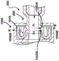
Standard U-shaped cantilever-insertion and removal forces
In the example shown, the U-shaped cantilever arm has a retaining catch arm or member 1312 that terminates in a catch 1330, as shown in fig. 3B, 3C (and fig. 4B, 4C and 5B, 5C). The clasp also has dual ramps 1333A, 1333B, wherein a first ramp 1333A of the dual ramps defines an insertion force and wherein a second ramp 1333B of the dual ramps defines a removal force, wherein the ramp angles (Fi, Fr) create a component of the force compressing the clasp 1333. In some such examples, the angles on the first and second ramps 1333A, 1333B (or, in other words, the insertion and removal ramps) may be changed to define respective insertion and removal forces. In some such examples, the first ramp 1333A and the second ramp 1333B have varying (different) ramp angles, thereby defining varying (different) respective removal and insertion forces. In other examples, the first ramp 1333A and the second ramp 1333B have substantially equal ramp angles, thereby defining substantially equal removal and insertion forces.
In the specific examples shown in fig. 3B, 3C (and additionally fig. 5B, 5C and 5f (i), 5f (ii)), the insertion and removal forces can vary. In some cases, the force may be varied by a moment created on the snap arm 1312. In particular, as shown in fig. 3B, 5B, and 5f (i), as the second mating member 200 is advanced into the first mating member 100, the insertion force will create a moment on the snap arm or member 1312 that will increase the force required to overcome the snap (in other words, the force required to move the generally U-shaped coupling member 1300 from its first configuration 1000A to its second configuration still in other words, in some embodiments, the coupling member 1000, such as the U-shaped coupling member 1300, is effectively biased in the first state or configuration 1000A, and the moment on the snap arm 1312 will effectively increase the force required to overcome the bias in order to move the U-shaped coupling member to its second state or configuration).
Conversely, when the second mating member 200 is removed from the first mating member 100 as shown in fig. 3C (and additionally fig. 5C and 5f (ii)), the removal force will create a moment on the snap arms 1312 that will reduce the force required to overcome the snap (in other words, the force required to move the generally U-shaped coupling member 1300 from its first configuration 1000A to its second configuration hi still other words, in some embodiments, the coupling member 1000, such as the U-shaped coupling member 1300, is effectively biased in the first state or configuration 1000A, and the moment on the snap arms 1312 will effectively reduce the force required to overcome the bias in order to move the U-shaped coupling member to its second state or configuration). In some such embodiments, the angle of the second or removal ramp 1333B may be provided as a relatively steeper angle, e.g., as compared to the angle of the first or insertion ramp 1333A, in order to increase the removal force to provide a relatively consistent insertion and removal force.
Inverted U-shaped cantilever-coupling member housed in housing
In other embodiments of the invention, as shown in fig. 4a (i), 4a (ii), 4a (iii), and 4a (iv), the coupling member 1000 including the U-shaped cantilever 1300 includes a pair of inverted U-shaped cantilevers 1302. As further shown in fig. 4a (i), 4a (ii), 4a (iii), and 4a (iv), a generally U-shaped cantilever 1300 is retained within the housing 124, in particular within the base portion 125b of the housing 124, as shown, and forms a proximal face of the first mating member 100 (in particular, with reference to fig. 4a (iv)). In these embodiments, the coupling member 1000, including the U-shaped cantilever 1300, is coupled to the housing 124, and in particular to the base portion 125b of the housing 124.
Similar to the embodiment previously described with respect to fig. 3B and 3C, the insertion and removal forces can vary in the specific example shown in fig. 4B and 4C. In some cases, the force may vary due to a moment created on the snap arm 1312. In particular, as shown in fig. 4B, as the second mating member 200 is advanced into the first mating member 100, the insertion force will create a moment on the snap arm or member 1312 that will reduce the force required to overcome the snap (in other words, the force required to move the generally U-shaped coupling member 1300 from its first configuration 1000A to its second configuration).
Conversely, when the second mating member 200 is removed from the first mating member 100 as shown in fig. 4B, the removal force will create a moment on the snap arms 1312 that will increase the force required to overcome the snap (in other words, the force required to move the generally U-shaped coupling member 1300 from its first configuration 1000A to its second configuration.
In some such embodiments, the angle of the first or insertion ramp 1333B may be provided as a relatively steeper angle, e.g., as compared to the angle of the second or removal ramp 1333A, in order to increase the insertion force required to provide a relatively consistent insertion and removal force.
U-shaped cantilever structure
In some such embodiments of the invention, as shown in fig. 3a (i) to 3d (ii), 4a (i) to 4C, 5a (i) to 5f (ii), the coupling member 1000 comprising the U-shaped cantilever 1300 comprises a moveable coupling member 1000, wherein it is moveable between a first state 1000A and a second state 1000 Bf. Additionally, in the example shown, the coupling member 1000 comprises a flexible coupling member, in particular, the U-shaped cantilever 1300 is flexible such that the cantilever 1312 is able to flex between the first state 1000A and the second state 1000B. In other examples of the coupling member 1000 embodying the U-shaped cantilever 1300, and thus the cantilever 1312, comprise a resilient material, thereby defining the resilient coupling member 1000.
In other embodiments of the present invention, the coupling member 1000 comprises an elastic coupling member that is capable of elastically deforming to transition between the first state 1000A and the second state 1000B and substantially avoid plastic deformation. In some such examples, the coupling member 1000 remains in the elastic region of the strain curve. Thus, in some embodiments that provide a U-shaped cantilever 1300 as outlined herein, the cantilever portion (in particular, cantilever 1312) is elastically deformable.
In some such embodiments, each cantilever of the pair of U-shaped cantilevers 1300 is deformed, in particular, upon insertion of the second mating member 200 into the first mating member 100, each cantilever is elastically deformable to move from the first state 1000A to the second state 1000B, thereby allowing passage of the second mating member 200 therethrough, and the coupling member 1000 defined by the U-shaped cantilevers 1300 is thereafter able to return to the first state 1000A to couple the second mating member 200 to the first mating member 100. In some such examples, each of the pair of U-shaped cantilevers 1300 is elastically deformable in a radial direction to move between a first state 1000A and a second state 1000B, e.g., as shown in fig. 3B-3C, 4B-4C, 5B-5C.
In some such embodiments, each of the pair of U-shaped cantilevers 1300 is movable in a plane P1, as shown in fig. 3B (but also applicable to fig. 3C, 4B, 4C, 5B, 5C), that is substantially coplanar with an advancement direction D of the auxiliary mating member into (or removed from) the housing.
In other words, each of the pair of U-shaped cantilevers 1300 is movable in a plane P1, the plane P1 being substantially coplanar with the plane D1, the plane D1 being substantially coplanar with an advancing direction D (or alternatively, a removing direction) of the auxiliary fitting member 200 into/out of the first fitting member 100.
Alternatively, in some embodiments, the pair of U-shaped cantilevers 1300 are movable in a plane p2 that is perpendicular to the direction of advancement D of the second mating member 200 into the housing 124 for insertion therein (extending in or out as shown in fig. 3B).
Substantially annular cantilever-coupling member housed in a casing
In an alternative embodiment of the invention, as shown in fig. 6a (i) to 6f (iv), 7A to 7D, 8A to 8f (iii), 13A to 13D, 14A to 14f (iii), a releasable coupling member 1000 is provided, wherein the coupling member 1000 is substantially housed or retained within the housing 124. In the illustrated embodiment, the coupling member 1000 is substantially free floating or loose within the housing 124.
In particular, with reference to fig. 6a (i) to 6f (iv), according to an embodiment of the present invention, there is provided a coupling mechanism 300 comprising a coupling member 1000 comprising at least one cantilever 1010 (or in other words, a cantilever portion or segment 1010), as shown in fig. 6d (i). In the illustrated example, the at least one cantilever 1010 comprises a simply supported beam configuration. Specifically, as shown, the at least one cantilever 1010 includes two cantilevers 1010 (or, in other words, a pair of cantilever portions or segments).
Referring again to fig. 6d (i), a pair of cantilevers 1010 are coupled together. As shown in some embodiments, the two cantilevers 1010 include two substantially straight segments (S) (or in other words, substantially straight portions or segments) coupled together using one or more arcuate segments (C), as shown in fig. 8A. In the particular example of this aspect as shown, each of the two straight segments (S) of the cantilever 1010 are coupled together at each of their respective ends by an arcuate segment (C).
In some of the illustrated embodiments, each of the two cantilevers 1010 includes a deflectable portion or region, wherein each of these deflectable portions is defined by a simply supported beam configuration. In the particular configuration shown, the substantially straight segment (S) defines a deflectable portion, wherein the maximum deflection (M) is substantially along a midpoint of the substantially straight segment (S). In some such examples, each of the deflectable portions includes one or more retention arms 1612, where the one or more retention arms include one or more snaps 1630.
In one particular example, the coupling member 1000 of the coupling mechanism 300 according to the present disclosure includes a generally annular disc-shaped configuration 1601, [ or in other words, the coupling member substantially includes an annular disc ], which is similar to the configuration shown in fig. 7A and 7B. Referring again to fig. 6d (i) and 8A, in the particular case of this example, the coupling member 1000 comprises a generally elliptical disc configuration [ or in other words, the coupling member substantially comprises an elliptical disc ]. As a feature of this aspect, the generally oval disk-shaped coupling member 1600 includes one or more retaining arms 1612 that terminate in one or more snaps 1630.
In the embodiments illustrated in fig. 6a (i) -6 f (iv), 7A-7D, 8A-8 f (iii), 13A-13D, 14A-14 f (iii), the generally oblong disc-shaped coupling member 1600 is functionally coupled to the housing 124, but in this particular embodiment it is substantially uncoupled or remains unattached or unattached to the housing during use such that it can move freely within the housing 124. Referring specifically to fig. 6d (ii), 6e (i), and 6e (ii), a generally oval disc-shaped coupling member 1600 is received within the housing base portion 124b of the sheath hub 122 and retained therein by the sheath hub cap 126. Thus, the combination of the housing base portion 124b and the sheath hub cap 126 forms a housing to enclose the generally oval disc-shaped coupling member 1600 therein, as further shown in fig. 6f (i).
As previously outlined above and referring now to fig. 6e (ii) (and 6f (i), 6f (ii), 6f (iii) showing an alternative second mating member 200), once second mating member 200 is inserted into first mating member 100 as shown in fig. 6f (iv), housing 124 (e.g., as defined by housing base portion 124b and sheath hub cap 126) interacts with generally elliptical disk-shaped coupling member 1600 to prevent translational movement of second mating member 200 relative to first mating member 100.
In some such examples, the sheath 124 interacts to prevent translational movement of the coupling member in the proximal and distal directions [ in particular, the sheath hub cap 126 prevents proximal retraction 200 of the second mating member, the base, such as the dilator 220 and the sheath base portion 124b, prevents distal movement of the mating member 200, such as the dilator 220 prevents further advancement of the dilator 220 into the sheath 120, and thus translationally locks the first mating member [ such as the sheath 120] and the second mating member [ such as the dilator 220 ]. Further, as shown in fig. 6B and 6C, the generally oval disc-shaped coupling member 1600 (and in particular the catch 1630 thereof) will rub against the distal face 124f of the housing base portion 124B, and this friction will thereby increase the insertion force, as shown in fig. 6B. Conversely, the generally oval disc-shaped coupling member 1600 (and in particular the catch 1630 thereof) will rub against the proximal face 126f of the sheath hub cap 126, and this friction will thereby increase the removal force. In some such examples, the generally oblong disc-shaped coupling member 1600 is functionally coupled to the housing 124, as it may not necessarily be attached or coupled (as provided in this embodiment), but rather is used to interact with the housing upon removal or insertion of the second mating member 200 to facilitate insertion and removal of the second mating member 200 and coupling thereof to the first mating member 100.
In some such embodiments of the invention, a coupling member 1000, such as a generally oval disk-shaped coupling member 1600, comprises a substantially flexible coupling member 1000. In a specific embodiment of the present invention, as shown in fig. 7A to 7D, a substantially oval disk-shaped coupling member 1600 is deformable, wherein the coupling member comprises an elastically deformable elastic coupling member.
In other words, in some embodiments of the invention, the coupling member 1000 substantially comprises a snap ring or strap 1601 which may have a configuration as shown in fig. 7A or 7B. In a particular example, the coupling member 1000 includes a generally oval snap ring or band 1600, as further shown in fig. 8A. In some such embodiments, the coupling member 1000 comprises a generally annular cantilever.
Substantially annular cantilever function
In the illustrated embodiment in which the coupling member 1000 comprises a generally elliptical disk-shaped coupling member 1600, the coupling member 1000 has a generally elliptical disk-shaped configuration in its first state 1000A (fig. 7A) and a generally circular or annular disk-shaped configuration in its second state 1000B (fig. 7B). Upon insertion of the second fitting member 200 into the first fitting member 100, the generally elliptical disk-shaped coupling member 1600 is deflectable to move (e.g., radially) from its elliptical disk-shaped configuration in its first state or configuration 1000A to its generally circular or annular disk-shaped configuration 100B in its second state, as shown in fig. 6B and 8B, to allow passage of the second fitting member 200 therethrough, and the generally elliptical disk-shaped coupling member 1600 can thereafter return to the first state 1000A defined by the elliptical configuration to couple the second fitting member 200 to the first fitting member 100, as shown in fig. 6C and 8f (iii).
Alternatively, the generally elliptical disc-shaped coupling member 1600 (or alternatively, the generally elliptical snap ring or band 1600) has a first engaged configuration in its first state 1000A comprising a generally elliptical disc-shaped configuration [ or a generally elliptical configuration ], and wherein the coupling member has a second non-engaged configuration in its second state 1000B comprising a generally annular disc-shaped configuration [ or a generally circular or annular configuration ]. Upon insertion of the second fitting member 200 into the first fitting member 100 (fig. 6B and 8f (i)), the generally elliptical disk-shaped coupling member 1600 is movable (e.g., radially) to its second, non-engaging configuration, including a generally annular disk-shaped configuration, such that the second fitting member 200 is advanced therein, and thereafter is movable to its first, engaging configuration, including a generally elliptical disk-shaped configuration, as shown in fig. 6C, 8f (iii), to couple the second fitting member 200 to the primary or first fitting member 100.
In some such examples, referring to fig. 6F (i), 6F9ii), 6F (iii), 6F (iv), a generally elliptical disc-shaped coupling member 1600 (or alternatively a generally elliptical snap ring or band 1600) is elastically deformable to move between a first state 1000A and a second state 1000B. More specifically, in some examples, upon insertion of the second mating member 200 into the housing of the first mating member 100, the generally elliptical disk-shaped coupling member 1600 (or alternatively an elliptical snap ring or band) can be moved radially outward, for example, to its second non-engaging configuration having a generally circular configuration 1000B [ to allow the second mating member 200, and in particular a raised portion of the dilator hub 222 (such as the tab or ring 228) to be advanced into the housing 124 of the first mating member 100 to pass over the generally elliptical disk-shaped coupling member 1600 (or alternatively an elastic snap ring or band), and in particular over one or more snaps 1630 positioned along the body of the coupling member. The generally elliptical disk-shaped coupling member 1600 can thereafter be moved to its first engaged configuration, including the generally elliptical configuration 1000A, to couple the second mating member 200 to the primary or first mating member 100 (in other words, the annular resilient ring or band is then configured to change or move back to its original generally elliptical shape or configuration (the generally elliptical snap ring or band), and thus change or move back to its original position (thereby allowing it to be positioned within the groove 226 of the dilator hub 222)).
As described herein, wherein the generally oval disc-shaped coupling member 1600 is elastically deformable in the radial direction [ R ] (as shown in fig. 6B, 6C and 8B, 8C) to move between the first state 1000A and the second state 1000B.
The snap-on force being independent of the hub length
In some embodiments, each of the pair of cantilever arms 1010 of a generally oval disk-shaped coupling member 1600 (shown in fig. 6D (i), 8A) is movable in a plane [ P2] perpendicular to the direction of advancement [ D ] of auxiliary fitting member 200 into housing 124 for insertion therein.
In some such embodiments, the snap force [ i.e., the force required to couple second mating member 200 to first mating member 100 using coupling mechanism 300 ] is independent of the proximal length of first mating member 100. In other words, the force required to move the generally elliptical disc-shaped coupling member 1600 from its first state 1000A to its second state 1000B to achieve coupling is independent of the length of the first mating member 100, such as the length of a medical device hub, such as the dilator hub 122. Thus, in some such examples, the frictional forces resulting from inserting the second mating member into first mating member 100 against coupling member 1000 may be minimized and, thus, there is reduced drag. Thus, additional friction is not substantially introduced and is not added to the snapping force required to deflect the coupling member 1000 to effect coupling (or otherwise snap and unlatch the second mating member 200). Thus, the insertion and removal forces are substantially determined by the coupling member 1000 (in particular the substantially oval disc-shaped coupling member 1600 with reference to fig. 8A, 8f (ii)), which may alternatively be referred to as a race track.
In some embodiments of the invention, the insertion force [ Fi ] and the removal force [ Fr ] are about 15 newtons. In other embodiments.
The coupling member is laterally inverted so as not to obstruct the view of the valve
In some embodiments of the invention, as shown in fig. 8f (i) and 8ff (iii), a first mating member 100, particularly including a first device 102, including a medical device such as a sheath 120, has a medical device hub 104 that also includes a valve 150, wherein a coupling member 1000, particularly a generally oval disc-shaped coupling member 1600, is oriented in a plane p2 perpendicular to a direction of advancement D of the second mating member 200 (as shown in fig. 8A), such that it does not substantially obstruct a user's visibility of the valve 150. In other words, coupling member 1000 in the illustrated orientation does not substantially require the use of a hub length (L), such as a length defined by the length of housing 124 as shown in fig. 6f (iii), for the length of cantilever 1010. In some such embodiments, the coupling mechanism 300 utilizes the width of the housing 124, as defined by the footprint provided by the diameter of the housing 124. This ensures that the snap force is independent of the hub length (L) and optimizes the visibility of the valve 150 through the opening 112 for the user by allowing the valve to be positioned relatively close to the opening 112.
The insertion force and the removal force are substantially equal/consistent
In some embodiments of the present invention, also as previously described above, referring now to fig. 8f (i), 8f (iii), coupling member 1000, in particular generally disc-shaped coupling member 1600 as previously described, includes a cantilever or retaining arm or member 1612 having a catch 1630 along a middle portion of the retaining arm or member 1612, for example at a region of maximum deflection. In some such examples of the releasable coupling mechanism 300, the catch 1630 also has dual ramps 1333A, 1333B, wherein a first ramp 1633A of the dual ramps defines an insertion force, and wherein a second ramp 1633B of the dual ramps defines a removal force, wherein each of the ramp angles (Fi, Fr) creates a component of force that compresses the catch 1630.
In some embodiments, the insertion force [ Fi ] for inserting the second mating member 200 into the coupling mechanism 300 to couple to the first mating member 100 through the coupling member 1000 (in particular, the generally oval disc-shaped coupling member 1600) is substantially equal to the removal force [ Fr ] [ fig. 8A-8F ] for removing the second mating member from the coupling mechanism to disengage from the first mating member. In some such examples, the angles on the first and second ramps 1633A, 1633B (or in other words, the insertion and removal ramps) may be changed to define respective insertion and removal forces. In some such examples, the first and second ramps 1633A, 1633B have varying (different) ramp angles, thereby defining varying (different) respective removal and insertion forces, as shown in fig. 8C. For example, fig. 8C provides a greater or steeper angle on the first ramp or insertion ramp 1633A than the ramp angle of the second ramp or removal ramp 1633B, which will increase the insertion force Fi as compared to the removal force (e.g., where the insertion force is the force required to utilize the coupling mechanism, e.g., to snap the second mating member 200 when using the snap mechanism 300, as shown). Thus, in the specific example shown in fig. 8C, embodiments of the present invention provide a way to vary or otherwise provide varying or different insertion and removal forces [ Fi ] and [ Fr ].
Tuning of insertion and removal forces
Thus, in such some embodiments of the invention, the insertion force [ Fi ] (for inserting the second mating member 200 into the coupling mechanism 300 for coupling to the first mating member 100 by the coupling member 1000, in particular the generally oval disc-shaped coupling member 1600) and the removal force [ Fr ] (for removing the second mating member 200 from the coupling mechanism for disengagement from the first mating member 100) are tunable, as shown in fig. 8A to 8C and 8d (i). Accordingly, some embodiments of the present invention provide a mechanism to tune or control the insertion and removal forces (Fi, Fr), for example, by changing the respective ramp angles of the insertion ramp 1633A and the removal ramp 1633B. In some such examples, for coupling member 1000, such as generally disc-shaped coupling member 1600, one or more orientation keys 1480 are provided so that generally disc-shaped coupling member 1600 may be inserted in a desired orientation, with appropriate insertion ramps 1633A and 1633B oriented with a desired appropriate insertion and removal ramp angle as shown in fig. 8e (i), 8e (ii), and 8e (iii). This may be able to facilitate assembly in which the removal ramp angle may be different from the insertion ramp angle.
Providing substantially equal insertion and removal forces
In other words, the first and second ramps 1633A, 1633B may be altered to define respective insertion and removal forces (Fi, Fr). In other examples, the first and second ramps 1633A, 1633B have substantially identical ramp angles, thereby defining substantially identical removal and insertion forces [ Fr ] and [ Fi ], respectively, as shown in fig. 8B.
The fastening force can be changed
In some embodiments of the present invention, as shown in fig. 8d (ii), 8e (ii), and 8e (iii), the snap force (e.g., the force required to snap the second mating member 200 to the first mating member 100 using the coupling member 1000, in particular the generally oval disc-shaped coupling member 1600), e.g., as defined by the insertion force [ Fi ] and/or the removal force [ Fr ], may be adjusted (or varied) by varying the wall thickness [ T ] and the snap height. In some such examples, referring to fig. 8f (ii), snap overlap [ X ] is defined as the overlap between snap 1630 and the portion of second mating member 200 that is inserted into first mating member 100 (e.g., for dilator 220), which portion of dilator 220 defines groove 226 of dilator 220 and/or ridge or bump 228 of dilator hub 222. In one such example, the wall thickness T is about 0.75mm and the snap overlap X is about 0.5 mm. In another example, the wall thickness T is about 1.0mm and the snap overlap is about 1.0 mm.
The coupling member remaining in the elastic region
In some such embodiments of the invention, as shown in fig. 7A, 7B and additionally as shown in fig. 7C, 7D, the generally disc-shaped coupling member 1600 of the releasable coupling mechanism 300 remains substantially in the elastic region when deformed, e.g., as it flexes between the first state 1000A and the second state 1000B. In some such embodiments of the invention, reference is again made to fig. 7A-7D and 8B-8C, wherein the insertion force [ Fi ] for inserting the second mating member 200 into the coupling mechanism 300 to couple to the first mating member 100 and the removal force [ Fr ] for removing the second mating member 200 from the coupling mechanism 300 to disengage from the first mating member are substantially consistent over multiple uses of the coupling mechanism 300. In other words, the insertion force [ Fi ] and the removal force [ Fr ] remain substantially unchanged over multiple uses. In some embodiments, the ability of the coupling member 1000 (e.g., the generally oval disc-shaped coupling member 1600) to remain in the elastic region during deformation and deflection substantially facilitates the insertion and removal forces (Fi, Fr) to remain substantially constant or unchanged over multiple uses.
In some such examples, the generally oval disc-shaped coupling member 1600 (race piece or snap piece) is able to flex as it is free floating within the housing 124, and the sheath hub length L is minimized as a result of flexing in a radial direction. The racetrack is integrally formed, or otherwise has a continuous geometry that facilitates reducing stress concentrations. Additionally, the snapping force can be adjusted or changed or tuned by changing the wall thickness T and the snapping overlap or snapping engagement X. In some such examples, the generally oval disc-shaped coupling member 1600 comprises polycarbonate. In further examples, the generally oval disc-shaped coupling member 1600 may comprise a resilient material. In another example, the material is ABS acrylonitrile butadiene. In some embodiments, the coupling member 1000, such as the generally oval disc-shaped coupling member 1600, experiences less than about 6% strain during flexure between the first state 100A and the second state 100B, wherein the coupling member 1000 will require greater than about 6% strain before plastic deformation occurs. Above this strain value, the coupling member 1000 will be plastically deformable, but the structure of the coupling member 1000 prevents this by providing elastic deformation over multiple uses. In some such examples, the strain experienced by coupling member 1000 is substantially dependent on a structure that allows for less than a 6% strain value (e.g., which is based on the structure of a generally oval disk-shaped coupling member 1600 having a generally racetrack geometry-based structure).
In some embodiments, as shown in fig. 13A, 13B, 13E, the generally oval disk-shaped coupling members are oriented such that the cantilever arms 1612 are oriented such that they are parallel to the hub cap plane 408 and the snaps 1630 are positioned along this plane. In some embodiments, as shown in fig. 13C and 13D, 13F, the generally oval disk-shaped coupling member is oriented such that the cantilever arms 1612 are oriented such that they are perpendicular to the hub top cap plane 408, and thus the snaps 1630 are positioned adjacent to the guide 402.
In an alternative embodiment of the invention, the coupling member 1000, in particular the generally disc-shaped coupling member 1600, is provided in the first mating member 100, which includes a steerable sheath 190 as shown in fig. 14A, 14B, 14C, 14D, 14E and 14F, wherein the generally disc-shaped coupling member 1600 is housed or retained within the housing 124 (formed by the housing base 124B and the hub cap 126), and may include additional components to house the coupling member in the housing. The coupling member is substantially free floating in the housing 124, wherein the coupling member 1000 (generally disc-shaped coupling member 1600) is configured to couple a second mating member comprising the dilator 220 to the steerable sheath 190.
General auditory feedback
In some embodiments of the invention, the coupling member 1000, such as the coupling members (the straight cantilevered coupling member 1200, the U-shaped coupling member 1300, and the generally elliptical disc-shaped coupling member 1600) is configured to generate audible feedback when moving between the first state 1000A and the second state 1000B, with reference to fig. 2a (ii), fig. 2B (ii), fig. 3B, fig. 3C, fig. 4B, fig. 4C, fig. 5B, fig. 5C. In some such examples, coupling member 1000 (specifically each of straight cantilevered coupling member 1200, U-shaped coupling member 13000, and generally oval disk-shaped coupling member 1600) interacts with second mating member 200 when inserted into first mating member 100 to generate audible feedback. In some such examples, once the coupling member returns from its second state 1000B to its first state 1000A, the respective snaps 1230, 1330, and 16300 of the respective coupling member interact with a portion of the second mating member 200 (such as the groove 226) to generate an audible click indicating that the second mating member 200 is inserted and coupled to the first mating member 100. Similarly in some such examples, upon removal of second mating member 200 from first mating member 100, respective snaps 1230, 1330, and 16300 of the respective coupling member interact with a portion of second mating member 200 (such as ridge or bump 228) upon return of the coupling member from its second state 1000B to its first state 1000A, thereby generating an audible click indicating removal and disengagement of second mating member 200 from first mating member 100.
Alternatives to runway embodiments
In some embodiments of the present invention, with particular reference to fig. 6a (i) -6 f (iv), 7A-7D, 8A-8 f (iii), a releasable coupling system 500 is provided that includes a first mating member 100 defining an opening 112 for receiving a second mating member 200 therethrough. In some such examples, second mating member 200 has a first diameter (e.g., a first diameter of the portion of dilator 220 defining groove 226) that defines an effective diameter that is less than opening 112, such that it is advanced through opening 112 into first mating member 100. System 500 also includes a means for increasing the effective diameter of second mating member 200, which includes coupling member 1000 (specifically, a generally oval disk-shaped coupling member 1600) positioned/located within first mating member 100. As second mating member 200 is inserted into first mating member 100 through opening 112 thereof, coupling member 1000 (specifically, generally oval disc-shaped coupling member 1600) couples to second mating member 200, thereby modifying [ increasing ] the effective diameter of second mating member 200 (e.g., at groove 226) such that the effective diameter of second mating member 200 is greater than opening 112 of first mating device 100, thereby preventing it from exiting therefrom/moving translationally therein. In addition, the effective diameter of second mating member 200 is larger than the distal opening in housing 124 of first mating member 100. Thus, when the coupling member 1000 is functionally coupled to the second mating member, the coupling member prevents or impedes the dilator hub 122 from moving out of the sheath hub 122 in the absence of force, thereby preventing the dilator hub from exiting through interaction with both the distal and proximal inner faces of the housing 124.
Alternative solutions
In other words, the embodiment shown in fig. 1A-1D, with particular reference to fig. 1B, the flexible coupling mechanism 300 further comprises a flexible locking member or component 1000 disposed within a first handle housing, such as the sheath housing 124, for releasably coupling the second handle portion 210 to the first handle portion 110. The flexible locking member or component has a first configuration 1000A (which may also be a locked configuration as shown in fig. 7A and 6C) and a second unlocked configuration 1000B (fig. 7B). As second handle portion 210 is initially advanced into the first handle portion, flexible locking member or component 1000 is able to move outwardly from its first locked configuration 1000A to its second unlocked configuration 1000B, out of the way of the second handle wider portion, and as second handle portion 210 is advanced further into first handle portion 110, flexible locking member or component 1000 can move inwardly into second handle groove portion 226, from its second, unlocked configuration to its first, locked configuration, as shown in figure 7A, to releasably couple the dilator hub 222 to the sheath hub 122, whereby as the dilator hub 222 is pulled, upon application of a force, the flexible locking member or component 1000 can be moved to its second, unlocked configuration to disengage the releasable locking mechanism. In some examples, the flexible locking member or component has a catch 132.
Rotary locking mechanism
According to some embodiments of the present invention, a coupling mechanism is provided that allows two devices to be coupled together such that they can be operated or manipulated together, thereby forming a rotational locking assembly or system that includes the two devices. In some such examples, the coupling mechanism includes a locking mechanism to allow one or more of rotational locking and/or translational locking of the two devices. In addition to the coupling mechanism 300 serving as a translational locking mechanism as described above, some embodiments of the invention provide a rotational locking mechanism 400 in addition to the releasable coupling mechanism 300. Some embodiments may include one or more of a releasable coupling mechanism and a rotational locking mechanism.
In some such examples, referring now to fig. 9a (i), 9a (ii), 9a (iii), and 9a (iv), the coupling mechanism includes a rotational locking mechanism 400 that includes a guide and/or corresponding cooperating features (such as guides 402, 404, and 406 within or along the two devices for effecting coupling of the sheath 100 and dilator 200) to allow the two devices to be operated or manipulated together. The present invention overcomes the problems of prior art systems in meeting the needs of the art: a) allowing the user the ability to rotate the attached device using the sheath or dilator hub or handle, and additionally b) allowing the dilator to be oriented in the same direction as the sheath bend (e.g., in embodiments where the dilator is rigid).
In one embodiment of the invention, a rotational key mechanism or rotational locking mechanism 400 is added to the first and second mating members 100, 200 and the dilator hub 104 and sheath hub 204, as described above and shown in fig. 1A and 1C, allowing them to be operated together, such as rotated or twisted together. A coupling mechanism including a rotational locking mechanism 400 as shown ensures proper alignment as shown in fig. 9a (i) and 9a (iv) (e.g., between first and second mating members 100 and 200, such as between sheath hub 122 and dilator hub 222, and thus dilator 120 and sheath 220) so that the assembly of sheath 120 and dilator 220 can be manipulated together, providing the assembly with the ability to transmit torque.
In the particular example shown in fig. 1A and 1C, the sheath hub 122 includes guides 402 that are funnel-shaped sides toward the valve. In one such embodiment, the housing 124 of the first mating member 100, and in particular the sheath 120, includes one or more guides 402 including angled or tapered guides or surfaces 406 as shown in fig. 9a (iii). The first mating member also includes one or more keyed surfaces or features 404, such as adjacent flat surfaces 408 that include keyed surfaces and torque transmitting surfaces. In some such embodiments, keying and torque transmission are provided on or using flat faces or surfaces 408. In some such examples, one or more of the guide 402 and the keying feature 404 define a first corresponding engagement feature 460 of the locking mechanism 400. The locking mechanism also includes angularly corresponding guide portions 202 on the dilator hub 222 that interact with the guide 402 to guide the dilator 222 into the sheath hub 122. In addition, the dilator hub 222 includes one or more corresponding keyed surfaces 204 that correspond to the keyed surfaces or features 404 of the sheath. In some such embodiments, one or more of the keyed surface 204 and the guide portion 202 of the dilator 220 provide the rotational locking mechanism 400 with a second corresponding engagement feature 260 to enable, for example, a cooperative coupling to enable rotational locking. The sheath hub also includes a flat face 404 to provide keying and torque transmission. In some such embodiments, the user can pivot the dilator hub 220, e.g., 3 to 9 o' clock, to release the catch. In some such embodiments, the force to disengage the rotational locking mechanism 400 is greater than about 10 newtons. In some embodiments, it is about 15 newtons.
In some such embodiments, the corner edges contact when the dilator is twisted due to the angled face 209 on the front of the dilator. In some examples, the corresponding flat faces may not mate when twisted. The torque applied at this angle generates a tripping force for rotating the locking mechanism. When the torque is sufficient to generate sufficient tripping force, then the rotational lock disengages and the dilator 220 trips from the sheath 120.
In another embodiment of the invention, as shown in fig. 9B and 9C, the rotational locking mechanism has a first corresponding engagement feature on the first mating member 100 that includes a key 428 (e.g., formed in a portion of the housing 124 such as the hub cap 126) and a second corresponding engagement feature on the second mating member 200 that includes a rib 228.
In another embodiment of the invention, as shown in fig. 10A, 10B, and 10C, the rotational locking mechanism has a first corresponding engagement feature on the first mating member 100 that includes a key 428 (e.g., formed in a portion of the housing 124 such as the cover or hub cap 126) and a second corresponding engagement feature on the second mating member 200 that includes a rib 228. In addition, chamfers are provided on the keys 428 and rounded or curved edges are provided on the ribs 228 to facilitate guiding the second mating member 200 (dilator 220) into the first mating member 100 (i.e., sheath 120). In some such examples, the key 428 includes a slot in the cover or hub cap 126, and the slot in the hub cap 126 and the rib 228 have corresponding mating angles that may facilitate surface contact.
In another embodiment of the invention, as shown in fig. 11A and 11B and fig. 12A and 12B, the rotational locking mechanism has a first corresponding engagement feature on the first mating member 100 that includes a key 428 (e.g., formed in a portion of the housing 124 such as the hub cap 126) [ the key includes a slot in the hub cap 126 in fig. 11A and 11B, and at least two grooves in fig. 12A, 12B ]. Rotational locking mechanism 400 also includes a second corresponding engagement feature that includes a rib 228 that may be angled on second mating member 200. In fig. 12A, 12B, two ribs 228 corresponding to the two grooves 428 are provided.
In some such embodiments, a rotational locking mechanism is provided that includes a first corresponding engagement feature on a first mating member, a second corresponding engagement feature on a second mating member, wherein the first and second corresponding features effect rotational locking. In some such examples, the first corresponding feature includes one or more guides. In one such example, the one or more guides comprise a funnel. In some such embodiments, the first corresponding feature comprises a keying feature. In some such embodiments, the keying feature comprises a substantially flat face. In some such embodiments, the second corresponding feature comprises one or more guide portions configured to mate with one or more guides of the first corresponding feature of the sheath. In some such embodiments, the second corresponding feature comprises a keying surface corresponding to the keying feature of the first corresponding feature.
Fig. 2-111 additionally illustrate additional embodiments of coupling mechanisms according to various embodiments of the present invention.
Various embodiments of coupling members
In some embodiments of the invention, the coupling member comprises a flexible coupling member. In some embodiments, the coupling member comprises a resilient coupling member. In other examples, the coupling member comprises an elastically deformable elastic coupling member.
Cantilever connecting member
In some embodiments, the coupling member comprises at least one cantilever.
Straight cantilever
In some embodiments, the coupling member comprises at least one straight or simple cantilever. In some such examples, at least one straight or simple cantilever is coupled to the housing of the first mating member. In some embodiments, the coupling member comprises two or more straight or (simple) cantilevered arms.
U-shaped cantilever
In some embodiments, the coupling member comprises at least one U-shaped cantilever. In some such embodiments, the at least one U-shaped cantilever comprises a resilient U-shaped cantilever. In one example, the coupling member includes a pair of U-shaped cantilevers. In certain instances, the coupling member includes a pair of inverted U-shaped cantilevered arms.
Substantially disc-shaped cantilever
In another embodiment, the coupling member comprises a substantially disc-shaped cantilever or a substantially annular coupling member. In one example, the coupling member includes a generally disc-shaped configuration. In one example, the coupling member includes a generally oval disc-shaped configuration. In one embodiment, the coupling member substantially comprises a snap ring or band (or a substantially annular snap ring or band). In particular examples of this aspect, the coupling member comprises a generally oval snap ring or band.
General auditory feedback
In some embodiments, the coupling member is configured to generate an audible feedback when moving between its first and second states. In some such embodiments, the coupling member interacts with the second mating member when inserted into the first mating member to generate the audible feedback. In some embodiments, once the coupling member returns from its second state to the first state, the coupling member interacts with the second mating member to generate an audible click.
Alternative solutions
In some embodiments, a locking mechanism is provided that includes a lock (member or component) retained (disposed/positioned) within a locking device for releasably coupling a second device thereto, wherein the second device is receivable by the locking device, wherein the lock (member or component) has a first state (or configuration) and a second state (or configuration), and wherein upon insertion of the second device into the locking device, the locking member is movable from its first state to its second state to allow passage of said second device therethrough, and thereafter movable to its first state to couple the second device to the locking device.
In some embodiments, there is provided a releasable locking assembly comprising: a locking device; a locking (member or component) retained (disposed/positioned) within the locking device for releasably coupling a second device receivable by the locking device to the locking device, wherein the locking component has a first state (or configuration) and a second state (or configuration), wherein upon insertion of the second device into the locking device, the locking component is movable from the first state to the second state to allow passage of the second device therethrough, and thereafter the locking component is movable to its first state to couple the second device to the locking device.
In some embodiments, a locking system is provided, the locking system comprising: a locking device; a lock (member or component) retained (seated/positioned) within the locking device; and a coupling member retained within the first mating member; and a second device receivable by the locking device to be releasably secured thereto by the locking member, wherein on insertion of the second device into the locking device, the locking component is movable from its first condition to its second condition to allow passage of the second device therethrough, and thereafter the locking component is movable to its first condition to couple the second device to the locking device.
Alternative solutions
In some embodiments, a releasable coupling mechanism is provided, the releasable coupling mechanism comprising: a housing defining a primary mating member [ defining an opening ] for receiving a secondary mating member to be coupled thereto; an elastically deformable retention member [ or member ] disposed [ or positioned ] within the housing for releasably coupling the secondary mating member to the housing upon insertion of the secondary mating member into the housing, wherein the elastically deformable retention member has a first engaged configuration and a second disengaged configuration, wherein upon insertion of the secondary mating member into the housing, the elastically deformable retention member is movable to its second disengaged configuration to cause the secondary mating member to advance into the housing and thereafter movable to its first engaged configuration to couple the secondary mating member to the primary mating member, thereby preventing [ disengagement of the secondary mating member therefrom, disengagement thereof in the absence of force, to prevent removal of the secondary mating member from its opening ].
In some such embodiments, the retention component comprises a deflectable member and is deflectable to its second, non-engaged configuration upon insertion of the secondary mating member, and thereafter is able to return to its initial, first, engaged configuration. In some such embodiments, the retention component comprises a flexible retention component. In some examples of the releasable coupling mechanism, the retaining member comprises a resilient retaining member. In some examples, the retention member comprises an elastically deformable retention member.
In some embodiments, the retention component is contained within the housing such that it is substantially enclosed by the housing. In some examples, the housing includes a top cover and a cover defining a cavity or space therein, and the retention component is disposed or positioned within the cavity or space defined by the housing. In some examples, the retention component is coupled to the housing. In some examples, the retention member is attached to the housing. In some examples, the retention member is attached to the housing at least at an end or tip thereof. In some examples, the retention member is integrally formed with the housing. In some examples, the retention component includes at least one retention arm or member, or in other words, one or more retention arms or members.
In some examples, at least one retention arm [ or member ], wherein the one or more retention arms [ or members ] terminate in one or more snaps. In some examples, at least one retaining arm [ or member ], wherein the one or more retaining arms [ or members ] comprise one or more cantilevers. In some examples, the one or more cantilevers comprise straight cantilevers. In some examples, the one or more cantilevers comprise a U-shaped cantilever.
In some embodiments of the U-shaped cantilever, the U-shaped cantilever in its first engaged configuration comprises a generally U-shaped configuration, and wherein the retention component in its second non-engaged configuration comprises a substantially compressed U-shaped configuration, wherein upon insertion of the secondary mating member into the housing, the resiliently deformable retention component is movable to its second non-engaged configuration comprising the substantially compressed U-shaped configuration to cause the secondary mating member to advance into the housing, and thereafter movable to its first engaged configuration comprising the generally U-shaped configuration to couple the secondary mating member to the primary mating member.
In some embodiments, wherein the U-shaped cantilever in its first engaged configuration comprises a generally U-shaped configuration, and wherein the retention component in its second non-engaged configuration comprises a substantially expanded-shaped configuration, wherein upon insertion of the secondary mating member into the housing, the resiliently deformable retention component is movable to its second non-engaged configuration comprising the substantially expanded U-shaped configuration to cause the secondary mating member to advance into the housing, and thereafter movable to its first engaged configuration comprising the generally U-shaped configuration to couple the secondary mating member to the primary mating member.
In some embodiments, the retention component is retained [ or loosely retained ] within the housing to be constrained or restricted therein. In other words, it is not substantially coupled to or attached to/rigidly fastened or securely attached thereto. In some such examples, the retention member is free floating within the housing. Some embodiments provide a free-floating retention member that is free-floating within the housing. In some such examples, the retention component is movable in a direction in a plane perpendicular to an advancement direction in which the auxiliary fitting member enters the housing for insertion therein.
In some embodiments, the retention component is movable in a direction in a plane perpendicular to the direction of advancement of the auxiliary fitting member into the housing for insertion therein. In some such examples, the resiliently deformable holding member comprises a generally disc-shaped structure. In some such examples, the elastically deformable holding member comprises a generally oval disc-shaped structure. In some embodiments, the retention component is movable in a direction in a plane coplanar with an advancement direction of the auxiliary fitting member into the housing for insertion therein. In some embodiments, the retention component is movable in a plane perpendicular to the direction of advancement of the auxiliary fitting member into the housing for insertion therein. In some such embodiments, the retaining member is capable of moving in a radial direction [ radially ].
In some embodiments, the retention component is biased to be in its first engaged configuration, wherein upon insertion of the secondary engagement member into the housing [ whereby the secondary engagement member applies an outward radial force against the retention component ], the retention component is movable to its second engaged configuration such that the secondary engagement member advances into the housing. In some embodiments, the retention component is independently movable relative to the housing. In some embodiments, the housing includes a cap (in other words a housing base portion) and a cover or hub cap defining a cavity [ or space ] therein for retaining the retention component therein without engagement therein.
In some embodiments, there is provided a releasable coupling mechanism comprising: a coupling comprising a primary receiving hub [ defining an opening ] for receiving an advancing secondary hub for insertion therein; and an independently movable coupling/clamping member disposed within the cavity of the main hub and enclosed therein; an independently movable gripping member having an engaging configuration and a non-engaging configuration, wherein upon insertion of the auxiliary hub portion into the main hub portion, the independently movable gripping member is initially movable to its non-engaging configuration to effect advancement of the [ engaging portion of ] the auxiliary hub portion and thereafter movable to its engaging configuration for gripping/grabbing the portion of the auxiliary hub portion to effect coupling to prevent disengagement thereof [ preventing removal of the auxiliary hub portion from the opening in the absence of force ], and wherein upon retraction of the auxiliary hub portion from the main hub portion, the independently movable gripping member is movable to its non-engaging configuration to cause disengagement thereof.
In one example, the independently movable clamping members comprise flexible clamping members. In one example, the independently movable clamping members comprise resilient clamping members. In one example, the independently movable clamping members are radially movable.
In one broad aspect, embodiments of the invention include a releasable locking mechanism for releasably coupling two medical devices, the releasable locking mechanism comprising: a first handle portion defining a housing including an opening for receiving a portion of a second handle portion therein, the second handle portion including a second handle wider portion and a second handle flute portion; a flexible locking member or component disposed within the first handle housing for releasably coupling the second handle portion to the first handle portion, the flexible locking member or component having a first locked configuration and a second unlocked configuration, wherein upon initial advancement of the second handle portion into the first handle portion, the flexible locking member or component is movable outwardly from its first locked configuration to its second unlocked configuration, out of the path of the second handle wider portion, upon interaction with the second handle wider portion, and upon further advancement of the second handle portion into the first handle portion, the flexible locking member or component is movable inwardly into the second handle groove portion, from its second unlocked configuration to its first locked configuration, to releasably couple the dilator hub to the sheath hub, whereby upon pulling of the dilator hub, the flexible locking member or component can move to its second, unlocked configuration upon application of a force to disengage the releasable locking mechanism.
In some examples, the flexible locking member or component comprises a resilient locking member or component. In another broad aspect, embodiments of the invention include a releasable locking mechanism for releasably coupling two medical devices, the releasable locking mechanism comprising: a first handle portion defining a housing including an opening for receiving a portion of a second handle portion therein, the second handle portion including a second handle wider portion and a second handle flute portion; a movable locking member or component disposed within the first handle housing for releasably coupling the second handle portion to the first handle portion, the movable locking member or component having a first locking configuration and a second non-locking configuration, wherein upon initial advancement of the second handle portion into the first handle portion, the movable locking member or component is movable outwardly from its first locking configuration to its second non-locking configuration, out of the path of the second handle wider portion, upon interaction with the second handle wider portion, and upon further advancement of the second handle portion into the first handle portion, the movable locking member or component is movable inwardly into the second handle groove portion, from its second non-locking configuration to its first locking configuration, to releasably couple the dilator hub to the sheath hub, whereby upon pulling of the dilator hub, the moveable locking member or component can move to its second, non-locking configuration upon application of a force to disengage the releasable locking mechanism.
In a further embodiment, there is provided a releasable locking mechanism for releasably coupling two devices, the releasable locking mechanism comprising:
a first receiving means defining a housing defining an opening for receiving a second insertion means therethrough, the second insertion means having a first diameter, the first diameter being less than an effective diameter of the opening such that the second insertion means is advanced into receiving the first means; means for increasing the effective diameter of a second device, the means comprising a moveable and/or flexible locking member or component, wherein upon insertion of the second device into a first device through an opening thereof, the moveable and/or flexible locking component is moveable about the second insertion means to form an interference fit with and/or interact with an incoming inserted second device to be coupled inserted therethrough to form a larger effective diameter of the second device to form an effective diameter of the second device that is larger than the opening of the first device to prevent its exit from the first device. Preventing or inhibiting the dilator hub from moving out of the sheath hub in the absence of force, thereby preventing the dilator hub from being dislodged.
In some embodiments, there is provided a releasable locking mechanism for releasably coupling two devices, the releasable locking mechanism comprising: a sheath hub defining an opening for receiving a dilator hub therethrough; an apparatus for increasing the effective diameter of a dilator hub, the apparatus comprising a moveable and/or flexible locking member or component, wherein the dilator hub has a smaller effective diameter than an opening into it to enable advancement into a sheath hub and after positioning within the sheath hub, and wherein once the dilator hub is advanced into the sheath hub, the moveable and/or flexible locking component moves around the dilator hub to form an interference fit and/or interaction with the entering dilator hub to prevent its exit from the opening, thereby forming a larger effective diameter on the dilator hub than the opening in the sheath hub to prevent/resist movement of the dilator hub out of the sheath hub without force to prevent the dilator hub from exiting.
As a further overview, some embodiments of the present invention provide a novel coupling for two devices. This may be advantageous, for example, where the dilator snaps into the sheath hub to connect two devices. This is typically done by the user on the proximal end as a user interface. By attaching both devices proximally, it is ensured that the distal portion remains fixed in the correct position while the user guides the sheath and dilator in the patient's anatomy.
The inventors of the present invention have invented a coupling mechanism that attempts to overcome the problems associated with the prior art mechanisms. Problems associated with existing devices are that they have snaps that degrade with use, have insufficient retention, provide insufficient tactile feedback, or generate debris. These snaps are typically embodied as rigid rings or tabs on the dilator hub that must be pressed into mating features on the sheath hub.
Additionally, there is a need in the art for a user to have the ability to rotate an attached device using a sheath hub or dilator handle, and/or otherwise allow a dilator (such as a rigid dilator) to be oriented in the same direction as the sheath bend.
The inventors of the present invention have developed a snap member with inherent flexibility that allows the snap to become/become substantially stable. In addition, a coupling mechanism is provided that provides a rotation key, for example, that has been added to the dilator and sheath hub. In some such embodiments, this ensures proper alignment and the ability to transmit torque. Accordingly, some embodiments of the present invention provide a coupling mechanism that provides a) a snap-fit mechanism with inherent flexibility, and/or b) a mechanical engagement between the dilator and the sheath hub that can transmit torque and provide consistent alignment.
In some embodiments, the direction of the sheath bend is indicated by a side port on the sheath hub, and is controlled by rotating the sheath hub.
In one broad aspect, embodiments of the invention include a releasable locking mechanism for releasably coupling two medical devices, the releasable locking mechanism comprising: a first handle portion defining a housing including an opening for receiving a portion of a second handle portion therein, the second handle portion including a second handle wider portion and a second handle flute portion; a flexible locking member or component disposed within the first handle housing for releasably coupling the second handle portion to the first handle portion; the flexible locking member or component having a first locked configuration and a second unlocked configuration; wherein upon initial advancement of the second handle portion into the first handle portion, the flexible locking member or component is movable outwardly from its first locked configuration to its second unlocked configuration out of the path of the second handle wider portion upon interaction with the second handle wider portion, and upon further advancement of the second handle portion into the first handle portion, the flexible locking member or component is movable inwardly into the second handle groove portion, from its second unlocked configuration to its first locked configuration, to releasably couple the dilator hub to the sheath hub, whereby upon pulling of the dilator hub, upon application of a force, the flexible locking member or component is movable to its second unlocked configuration to disengage the releasable locking mechanism.
In another broad aspect, embodiments of the invention include a releasable locking mechanism for releasably coupling two medical devices, the releasable locking mechanism comprising: a first handle portion defining a housing including an opening for receiving a portion of a second handle portion therein, the second handle portion including a second handle wider portion and a second handle flute portion; a movable locking member or component disposed within the first handle housing for releasably coupling the second handle portion to the first handle portion; the movable locking member or component having a first locking configuration and a second non-locking configuration; wherein upon initial advancement of the second handle portion into the first handle portion, the movable locking member or component is movable outwardly from its first locked configuration to its second unlocked configuration out of the path of the second handle wider portion upon interaction with the second handle wider portion, and upon further advancement of the second handle portion into the first handle portion, the movable locking member or component is movable inwardly into the second handle groove portion, from its second unlocked configuration to its first locked configuration, to releasably couple the dilator hub to the sheath hub, whereby upon pulling of the dilator hub, upon application of a force, the movable locking member or component is movable to its second unlocked configuration to disengage the releasable locking mechanism.
As a feature of this broad aspect, the means for increasing the effective diameter of the dilator hub comprises a moveable and/or flexible locking member or component, wherein the dilator hub has a smaller effective diameter, thereby entering the sheath hub, and once positioned within the sheath hub, the moveable and/or flexible locking component moves around the dilator hub, forming an interference fit and/or interaction with the entering dilator hub, thereby preventing the entering dilator hub from exiting by forming a larger effective diameter on the dilator hub, wherein the effective diameter of the dilator hub is larger than the opening in the sheath hub, thereby preventing/impeding the dilator hub from moving out of the sheath hub without force, thereby preventing the dilator hub from exiting.
The embodiments of the invention described above are intended to be exemplary only. Accordingly, the scope of the invention is intended to be limited only by the scope of the appended claims.
It is to be understood that certain features of the invention, which are, for clarity, described in the context of separate embodiments, may also be provided in combination in a single embodiment. Conversely, various features of the invention which are, for brevity, described in the context of a single embodiment, may also be provided separately or in any suitable subcombination.
While the invention has been described in conjunction with specific embodiments thereof, it is evident that many alternatives, modifications and variations will be apparent to those skilled in the art. Accordingly, the present invention is intended to embrace all such alternatives, modifications and variances which fall within the broad scope of the appended claims. All publications, patents, and patent applications mentioned in this specification are herein incorporated in their entirety by reference into the specification, to the same extent as if each individual publication, patent, or patent application was specifically and individually indicated to be incorporated herein by reference. In addition, citation or identification of any reference in this patent application shall not be construed as an admission that such reference is available as prior art to the present invention.
Claims (154)
1. A releasable coupling mechanism comprising:
a coupling member configured to be associated with a first mating member for releasably coupling a second mating member receivable by the first mating member to the first mating member;
wherein the coupling member has a first state and a second state; and is
Wherein the coupling member is movable from the first state to the second state to allow passage of the second mating member when the second mating member is inserted into the first mating member, and thereafter is movable from the second state to the first state to releasably couple the second mating member to the first mating member.
2. The releasable coupling mechanism of claim 1, wherein the releasable coupling mechanism comprises a translational locking mechanism that prevents translational movement of the first and second cooperating members relative to each other.
3. The releasable coupling mechanism of claim 2, wherein the coupling member is functionally coupled to the housing of the first mating member.
4. The releasable coupling mechanism of claim 3, wherein the coupling member is retained within the first mating member.
5. The releasable coupling mechanism of claim 3, wherein the coupling member is coupled to a housing of the first mating member.
6. The releasable coupling mechanism of claim 5, wherein the coupling member is attached to the housing.
7. The releasable coupling mechanism of claim 6, wherein the coupling member is integrally formed with the housing.
8. The releasable coupling mechanism of claim 7, wherein the coupling member comprises a flexible coupling member.
9. The releasable coupling mechanism of claim 7, wherein the coupling member comprises at least one cantilever arm.
10. The releasable coupling mechanism of claim 9, wherein the at least one cantilever comprises at least one straight cantilever.
11. The releasable coupling mechanism of claim 10, wherein the at least one straight cantilever arm is integrally formed with a top cover of the housing.
12. The releasable coupling mechanism of claim 11, wherein the at least one straight cantilever arm comprises one or more retaining arms.
13. The releasable coupling mechanism of claim 12, wherein the one or more retaining arms terminate in one or more snaps.
14. The releasable coupling mechanism of claim 10, wherein the at least one straight cantilever comprises two or more straight cantilevers.
15. The releasable coupling mechanism of claim 14, wherein each of the two or more straight cantilever arms is deflectable to move from the first state to a second state upon insertion of the second mating member into the first mating member, thereby allowing passage of the second mating member therethrough, and the coupling member is thereafter returnable to the first state to couple the second mating member to the first mating member.
16. The releasable coupling mechanism of claim 15, wherein each of the two or more straight cantilevers is deflectable in a radial direction to move between the first state and the second state.
17. The releasable coupling mechanism of claim 16, wherein each of the two or more straight cantilever arms is movable in a plane that is coplanar with a direction of advancement of an auxiliary engagement member into the housing for insertion therein.
18. The releasable coupling mechanism of claim 5, wherein the coupling member comprises a moveable coupling member.
19. The releasable coupling mechanism of claim 18, wherein the coupling member comprises a flexible coupling member.
20. The releasable coupling mechanism of claim 19, wherein the coupling member comprises a resilient coupling member.
21. The releasable coupling mechanism of claim 20, wherein the coupling member comprises an elastically deformable resilient coupling member.
22. The releasable coupling mechanism of claim 21, wherein the coupling member comprises at least one cantilever arm.
23. The releasable coupling mechanism of claim 22, wherein the coupling member comprises at least one U-shaped cantilever.
24. The releasable coupling mechanism of claim 23, wherein the at least one U-shaped cantilever comprises a resilient U-shaped cantilever.
25. The releasable coupling mechanism of claim 24, wherein the at least one U-shaped cantilever comprises a pair of U-shaped cantilevers.
26. The releasable coupling mechanism of claim 25, wherein each U-shaped cantilever of the pair of U-shaped cantilevers is deflectable to move from the first state to a second state upon insertion of the second mating member into the first mating member, allowing passage of the second mating member therethrough, and the coupling member is thereafter returnable to the first state to couple the second mating member to the first mating member.
27. The releasable coupling mechanism of claim 25, wherein each U-shaped cantilever of the pair of U-shaped cantilevers is elastically deformable to move from the first state to a second state upon insertion of the second mating member into the first mating member, allowing passage of the second mating member therethrough, and the coupling member is thereafter returnable to the first state to couple the second mating member to the first mating member.
28. The releasable coupling mechanism of claim 27, wherein each U-shaped cantilever of the pair of U-shaped cantilevers is elastically deformable in a radial direction to move between the first state and the second state.
29. The releasable coupling mechanism of claim 28, wherein each U-shaped cantilever of the pair of U-shaped cantilevers is movable in a plane that is coplanar with a direction of advancement of an auxiliary mating member into the housing for insertion therein.
30. The releasable coupling mechanism of claim 28, wherein each U-shaped cantilever of the pair of U-shaped cantilevers is movable in a plane perpendicular to an advancement direction of an auxiliary engagement member into the housing for insertion therein.
31. The releasable coupling mechanism of claim 29, wherein each U-shaped cantilever of the pair of U-shaped cantilevers comprises one or more retaining arms.
32. The releasable coupling mechanism of claim 31, wherein the one or more retaining arms terminate in one or more snaps.
33. The releasable coupling mechanism of claim 25, wherein the pair of U-shaped cantilevers are substantially contained within the housing.
34. The releasable coupling mechanism of claim 33, wherein the housing is integrally formed and the U-shaped cantilever is substantially contained within the integrally formed housing.
35. The releasable coupling mechanism of claim 33, wherein the housing includes a housing base and a top cover, and the U-shaped cantilever is substantially contained within the housing base and the top cover.
36. The releasable coupling mechanism of claim 32, wherein the coupling member comprises a pair of inverted U-shaped cantilever arms.
37. The releasable coupling mechanism of claim 3, wherein the coupling member is substantially contained within the housing.
38. The releasable coupling mechanism of claim 37, wherein the coupling member is substantially free within the housing.
39. The releasable coupling mechanism of claim 37, wherein the coupling member is substantially unattached to the housing.
40. The releasable coupling mechanism of claim 37, wherein the coupling member comprises a flexible coupling member.
41. The releasable coupling member of claim 40, wherein the coupling member is deformable, wherein the coupling member comprises an elastically deformable resilient coupling member.
42. The releasable coupling mechanism of claim 41, wherein the coupling member comprises at least one cantilever arm.
43. The releasable coupling mechanism of claim 42, wherein the at least one cantilever comprises a simply supported beam configuration.
44. The releasable coupling mechanism of claim 43, wherein the at least one cantilever comprises a pair of cantilevers.
45. The releasable coupling mechanism of claim 44, wherein the at least one cantilever comprises a pair of cantilevers coupled together.
46. The releasable coupling mechanism of claim 45, wherein the two cantilevers comprise two substantially straight segments coupled together using one or more arcuate segments.
47. The releasable coupling mechanism of claim 46 wherein each of the two straight sections of the cantilever are coupled together at each of their respective ends by an arcuate section.
48. The releasable coupling mechanism of claim 47, wherein each of the two cantilever arms includes a deflectable portion.
49. The releasable coupling mechanism of claim 48 wherein each of the deflectable portions is defined by a simply supported beam configuration.
50. The releasable coupling mechanism of claim 48, wherein each of the deflectable portions comprises one or more retaining arms.
51. The releasable coupling mechanism of claim 50, wherein the one or more retaining arms comprise one or more snaps.
52. The releasable coupling member of claim 51, wherein the coupling member comprises a generally annular disc-shaped configuration defining a generally annular disc.
53. The releasable coupling member of claim 52, wherein the coupling member comprises a generally elliptical disk configuration defining a generally elliptical disk.
54. The releasable coupling mechanism of claim 50, wherein the coupling member substantially comprises a snap ring.
55. The releasable coupling mechanism of claim 54, wherein the coupling member comprises a generally oval snap ring.
56. The releasable coupling member of claim 52, wherein the coupling member has a generally oval disc-shaped configuration in its first state and a generally disc-shaped configuration in its second state;
wherein upon insertion of the second mating member into the first mating member, the coupling member is deflectable to move from its elliptical disk-shaped configuration in its first state to its generally circular disk-shaped configuration, thereby allowing passage of the second mating member therethrough, and thereafter the coupling member is returnable to the first state defined by the elliptical configuration to couple the second mating member to the first mating member.
57. The releasable coupling mechanism of claim 52, wherein the coupling member has a first engaged configuration in its first state, the first engaged configuration comprising a configuration defined by a generally oval disc-shaped configuration, and wherein the coupling member has a second non-engaged configuration in its second state, the second non-engaged configuration comprising a configuration defined by a generally annular disc-shaped configuration;
wherein upon insertion of the second mating member into the first mating member, the coupling member is movable to its second, non-engaging configuration, including the generally annular disc-shaped configuration, to cause the second mating member to advance therein, and thereafter movable to its first, engaging configuration, including the generally elliptical disc-shaped configuration, to couple the second mating member to the first mating member.
58. The releasable coupling member of claim 55, wherein the generally elliptical snap ring has a generally elliptical configuration in its first state and a generally circular configuration in its second state;
wherein the generally elliptical snap ring is elastically deformable upon insertion of the second mating member into the first mating member to move from the first state defined by an elliptical configuration to a second state defined by a circular configuration to allow passage of the second mating member therethrough, and the coupling member is thereafter returnable to the first state defined by the elliptical configuration to couple the second mating member to the first mating member.
59. The releasable coupling mechanism of claim 55 wherein the generally elliptical snap ring has a first engaged configuration in its first state, the first engaged configuration comprising a configuration defined by a generally elliptical disc-shaped configuration, and wherein the coupling member has a second unengaged configuration in its second state, the second unengaged configuration comprising a configuration defined by a generally annular disc-shaped configuration;
wherein upon insertion of the second mating member into the housing of the first mating member, the generally elliptical snap ring is movable outwardly [ e.g., radially ] to its second non-engaging configuration comprising the generally annular snap ring to allow activation of the auxiliary mating member, in particular to allow a boss portion of a dilator hub to be advanced into the housing of the first mating member to move past a resilient ring or band, in particular past one or more snaps positioned along a body portion such as the resilient ring or band, and thereafter movable to its first engaging configuration comprising the generally elliptical snap ring to couple the second mating member to the first mating member.
60. The releasable coupling member of claim 56, wherein the coupling member is resiliently deformable in a radial direction to move between the first and second states.
61. The releasable coupling mechanism of claim 44, wherein each cantilever arm of the pair of cantilever arms is movable in a plane perpendicular to a direction of advancement of an auxiliary engagement member into the housing for insertion therein.
62. The releasable coupling mechanism of claim 60, wherein the snapping force is independent of a proximal length of the first mating member.
63. The releasable coupling mechanism of claim 62, wherein the first mating member comprises a medical device hub, wherein the snapping force is independent of a length of the hub.
64. The releasable coupling mechanism of claim 44, wherein the snapping force required to couple the second coupling member to the first coupling member using the snapping mechanism is independent of a proximal length of the first mating member.
65. The releasable coupling mechanism of claim 64, wherein the first mating member comprises a medical device hub, wherein the snapping force is independent of a length of the hub.
66. The releasable coupling mechanism of claim 65, wherein the medical device hub further comprises a valve, wherein the coupling member is oriented in a plane perpendicular to the direction of advancement of the second mating member, whereby it does not substantially obstruct visibility of the valve.
67. The releasable coupling mechanism of claim 60, wherein an insertion force for inserting the second cooperating member into the coupling mechanism to couple to the first cooperating member through the coupling member is substantially equal to a removal force for removing the second cooperating member from the coupling mechanism to disengage from the first cooperating member.
68. The releasable coupling mechanism of claim 67 wherein the coupling member remains in the elastic region when deformed.
69. The releasable coupling mechanism of claim 60, wherein the insertion force for inserting the second mating member into the coupling mechanism to couple to the first mating member and the removal force for removing the second mating member from coupling mechanism to disengage from the first mating member are substantially consistent over multiple uses of the coupling mechanism.
70. The releasable coupling mechanism of claim 69 wherein the coupling member remains in the resilient region when deformed.
71. The releasable coupling mechanism of claim 41 wherein the coupling member remains in the resilient region when deformed.
72. The releasable coupling mechanism of claim 60, wherein the insertion force and the removal force are tunable.
73. The releasable coupling mechanism of claim 60, wherein the catch has a double ramp, wherein:
a first ramp of the dual ramps defines the insertion force; and is
Wherein a second ramp of the dual ramp defines the removal force.
74. The releasable coupling mechanism of claim 73, wherein the first and second ramps are variable to define respective insertion and removal forces.
75. The releasable coupling mechanism of claim 73, wherein the first and second ramps have varying ramp angles, thereby defining varying respective removal and insertion forces.
76. The releasable coupling mechanism of claim 74, wherein the first and second ramps have substantially different ramp angles, thereby defining substantially different removal and insertion forces.
77. The releasable coupling mechanism of claim 74, wherein the first and second ramps have substantially equal ramp angles, thereby defining substantially equal removal and insertion forces.
78. The releasable coupling mechanism of claim 53 wherein the coupling member is configured to generate audible feedback when moved between its first and second states.
79. The releasable coupling mechanism of claim 78, wherein the coupling member interacts with the second mating member when inserted into the first mating member to generate audible feedback.
80. The releasable coupling mechanism of claim 79, wherein upon return of the coupling member from its second state to the first state, the coupling member interacts with the second mating member to generate an audible click.
81. A releasable coupling system, comprising:
a first mating member defining an opening for receiving a second mating member therethrough, the second mating member having a first diameter defining an effective diameter, the effective diameter being smaller than the opening, thereby enabling the second mating member to be advanced through the opening into the first mating member; and
means for increasing the effective diameter of the second mating member, the means comprising a coupling member positioned within the first mating member;
wherein the coupling member is coupled to the second mating member when the second mating member is inserted into the first mating member through the opening of the first mating member, thereby modifying the effective diameter of the second mating member such that the effective diameter of the second mating member is greater than the opening of the first mating device, thereby preventing the second mating member from being inserted into the first mating member through the opening of the first mating member
The second engagement member moves translationally relative to the first engagement member.
82. The releasable coupling mechanism of claim 1, wherein the coupling member comprises a flexible coupling member.
83. The releasable coupling mechanism of claim 1, wherein the coupling member comprises a resilient coupling member.
84. The releasable coupling mechanism of claim 1, wherein the coupling member comprises an elastically deformable resilient coupling member.
85. The releasable coupling mechanism of claim 1, wherein the coupling member comprises at least one cantilever arm.
86. The releasable coupling mechanism of claim 85, wherein the coupling member comprises at least one simple cantilever.
87. The releasable coupling mechanism of claim 86, wherein the at least one simple cantilever is coupled to a housing of the first mating member.
88. The releasable coupling mechanism of claim 87, wherein the coupling member comprises two or more simple cantilever arms.
89. The releasable coupling mechanism of claim 83, wherein the coupling member comprises at least one U-shaped cantilever.
90. The releasable coupling mechanism of claim 89, wherein the at least one U-shaped cantilever comprises a resilient U-shaped cantilever.
91. The releasable coupling mechanism of claim 90, wherein the coupling member comprises a pair of U-shaped cantilever arms.
92. The releasable coupling mechanism of claim 91, wherein the coupling member comprises a pair of inverted U-shaped cantilever arms.
93. The releasable coupling mechanism of claim 84, wherein the coupling member comprises a generally disc-shaped configuration.
94. The releasable coupling mechanism of claim 93, wherein the coupling member comprises a generally oval disc-shaped configuration.
95. The releasable coupling mechanism of claim 84, wherein the coupling member substantially comprises a snap-fit band.
96. The releasable coupling mechanism of claim 95, wherein the coupling member comprises a generally oval-shaped snap-fit band.
97. A releasable coupling assembly comprising:
a first mating member; and
the coupling mechanism of any one of claims 1 to 96.
98. A releasable coupling assembly comprising:
a first mating member;
a coupling mechanism including a coupling member associated with the first mating member for releasably coupling a second mating member receivable by the first mating member to the first mating member;
wherein the coupling member has a first configuration and a second configuration;
wherein the coupling member is movable from its first condition to its second condition to allow passage of the second fitting member therethrough upon insertion of the second fitting member into the first fitting member, and thereafter movable to its first condition to couple the second fitting member to the first fitting member of the releasable coupling assembly.
99. A releasable coupling system, comprising:
a first mating member;
a coupling mechanism according to any one of claims 1 to 96; and
a second mating member.
100. A releasable coupling system, comprising:
a first mating member;
a coupling mechanism comprising a coupling member associated with the first mating member; and
a second mating member receivable by the first mating member to be secured to the first mating member by the coupling member,
wherein the coupling member is movable from a first state to a second state upon insertion of the second mating member into the first mating member to allow passage of the second mating member therethrough, and thereafter the coupling member is movable to the first state to couple the second mating member to the first mating member.
101. The releasable coupling system of claim 100, wherein the first mating member includes a first mating member housing, wherein the coupling member is functionally coupled to the housing of the first mating member.
102. The releasable coupling system of claim 101, wherein the second mating member comprises a groove; and is
Wherein the coupling member is receivable in the groove of the second coupling member defining a cooperating arrangement therebetween for releasably coupling the first and second mating members.
103. The releasable coupling system of claim 101, wherein:
the coupling member defines a first corresponding cooperating engagement feature; and is
The second mating member includes a second corresponding cooperating engagement feature;
wherein the first corresponding cooperating engagement feature of the coupling member is operable to cooperatively engage to the second corresponding cooperating engagement feature of the second coupling member to define a cooperative engagement between the first and second corresponding portions for releasably coupling the first and second mating members.
104. The releasable coupling system of claim 103, wherein the first corresponding cooperating engagement feature comprises a catch of the coupling member.
105. The releasable coupling system of claim 103, wherein the second corresponding cooperating engagement feature comprises a groove of the second mating member.
106. The releasable coupling mechanism of claim 1, wherein the coupling member is configured to generate an audible feedback when moving between its first and second states.
107. The releasable coupling mechanism of claim 106, wherein the coupling member interacts with the second mating member when inserted into the first mating member to generate audible feedback.
108. The releasable coupling mechanism of claim 107, wherein upon return of the coupling member from its second state to the first state, the coupling member interacts with the second mating member to generate an audible click.
109. A locking mechanism, comprising:
a locking member disposed within a locking device for releasably coupling a second device to the locking device, wherein the second device is receivable by the locking device;
wherein the locking member has a first configuration and a second configuration;
wherein the locking member is movable from its first configuration to its second configuration to allow passage of the second device therethrough upon insertion of the second device into the locking device, and thereafter movable to its first configuration to couple the second device to the locking device.
110. A releasable locking assembly comprising:
a locking device;
a locking member remaining disposed within the locking device for releasably coupling a second device receivable by the locking device to the locking device;
wherein the locking member has a first configuration and a second configuration;
wherein the locking means is movable from a first configuration to a second configuration to allow passage of the second device therethrough upon insertion of the second device into the locking device, and thereafter the locking means is movable to its first configuration to couple the second device to the locking device.
111. A locking system, comprising:
a locking device;
a locking member disposed within the locking device; and
a coupling member retained within the first mating member; and
a second means receivable by the locking means for releasable securement to the locking means by the locking member,
wherein the locking means is movable from its first condition to its second condition to allow passage of the second device therethrough upon insertion of the second device into the locking device, and thereafter movable to its first condition to couple the second device to the locking device.
112. A releasable coupling mechanism comprising:
a housing defining a primary mating member defining an opening for receiving a secondary mating member to be coupled thereto; and
an elastically deformable retention feature positioned within the housing for releasably coupling the auxiliary engagement member to the housing upon insertion of the auxiliary engagement member into the housing;
wherein the resiliently deformable retaining part has a first engaged configuration and a second unengaged configuration, wherein on insertion of the secondary mating member into the housing, the resiliently deformable retaining part is movable to its second unengaged configuration to cause the secondary mating member to advance into the housing and thereafter movable to its first engaged configuration to couple the secondary mating member to the primary mating member to prevent the secondary mating member from being disengageable therefrom, from being disengaged in the absence of a force to prevent the secondary mating member from being removable from the opening thereof.
113. The releasable coupling mechanism of claim 112, wherein the retention component comprises a deflectable member and is deflectable to its second, non-engaged configuration upon insertion of the secondary engagement member and thereafter is returnable to its initial, first, engaged configuration.
114. The releasable coupling mechanism of claim 113, wherein the retaining member comprises a flexible retaining member.
115. The releasable coupling mechanism of claim 113, wherein the retaining member comprises a resilient retaining member.
116. The releasable coupling mechanism of claim 115, wherein the retaining member comprises an elastically deformable retaining member.
117. The releasable coupling mechanism of claim 116, wherein the retaining member is housed within the housing.
118. The releasable coupling mechanism of claim 117, wherein the housing comprises a cap and a cover defining a cavity therein, wherein the retention component is disposed within the cavity defined by the housing.
119. The releasable coupling mechanism of claim 117, wherein the retaining member is coupled to the housing.
120. The releasable coupling mechanism of claim 119, wherein the retaining member is attached to the housing.
121. The releasable coupling mechanism of claim 120, wherein the retaining member is attached to the housing at least at an end thereof.
122. The releasable coupling mechanism of claim 120, wherein the retaining member is integrally formed with the housing.
123. The releasable coupling mechanism of claim 120, wherein the retaining component comprises one or more retaining arms.
124. The releasable coupling mechanism of claim 123, wherein the one or more retaining arms terminate in one or more snaps.
125. The releasable coupling mechanism of claim 124, wherein the one or more retaining arms comprise one or more cantilever arms.
126. The releasable coupling mechanism of claim 125, wherein the one or more cantilevers comprise straight cantilevers.
127. The releasable coupling mechanism of claim 125, wherein the one or more cantilevers comprise a U-shaped cantilever.
128. The releasable coupling mechanism of claim 127, wherein the U-shaped cantilever in its first engaged configuration comprises a generally U-shaped configuration, and wherein the retaining member in its second non-engaged configuration comprises a substantially compressed shape configuration; and is
Wherein upon insertion of the secondary mating member into the housing, the resiliently deformable retention component is movable to its second non-engaging configuration comprising the substantially compressed U-shaped configuration to cause the secondary mating member to advance into the housing and thereafter movable to its first engaging configuration comprising the substantially U-shaped configuration to couple the secondary mating member to the primary mating member.
129. The releasable coupling mechanism of claim 127, wherein the U-shaped cantilever in its first engaged configuration comprises a generally U-shaped configuration, and wherein the retaining member in its second non-engaged configuration comprises a substantially expanded shape configuration;
wherein upon insertion of the secondary mating member into the housing, the resiliently deformable retention component is movable to its second non-engaging configuration comprising the substantially expanded U-shaped configuration to cause the secondary mating member to advance into the housing and thereafter movable to its first engaging configuration comprising the substantially U-shaped configuration to couple the secondary mating member to the primary mating member.
130. The releasable coupling mechanism of claim 117, wherein the retaining member is loosely retained within the housing to be retained, whereby wherein the retaining member is not coupled to the housing or is attached to the housing by a secure attachment.
131. The releasable coupling mechanism of claim 130, wherein the retaining member is free floating within the housing.
132. The releasable coupling mechanism of claim 130, wherein the retaining component is movable in a direction in a plane perpendicular to a direction of advancement of the secondary engagement member into the housing for insertion therein.
133. The releasable coupling mechanism of claim 130, wherein the retaining component is movable in a direction in a plane perpendicular to a direction of advancement of the secondary engagement member into the housing for insertion therein.
134. The releasable coupling mechanism of claim 112, wherein the resiliently deformable holding member comprises a generally disc-shaped structure.
135. The releasable coupling mechanism of claim 134, wherein the resiliently deformable holding member comprises a generally oval disc shaped structure.
136. The releasable coupling mechanism of claim 135, wherein the resiliently deformable holding member in its first engaged configuration comprises a generally oval disc-shaped configuration, and wherein the holding member in its second unengaged configuration comprises a generally annular disc-shaped configuration;
wherein upon insertion of the secondary mating member into the housing, the resiliently deformable retaining means is movable to its second non-engaging configuration comprising the generally annular disc-shaped configuration to cause the secondary mating member to advance into the housing and thereafter movable to its first engaging configuration comprising the generally elliptical disc-shaped configuration to couple the secondary mating member to the primary mating member.
137. The releasable coupling mechanism of claim 112, wherein the resiliently deformable retaining means comprises a snap member.
138. The releasable coupling mechanism of claim 137, wherein the resiliently deformable holding component comprises a generally oval-shaped snap member.
139. The releasable coupling mechanism of claim 138, wherein the retention component in its first engaged configuration includes a generally elliptical snap member defining a generally elliptical shape, and wherein the retention component in its second non-engaged configuration includes a generally circular snap member defining a generally circular shape;
wherein the generally elliptical snap member is movable radially outwardly to its second non-engaging configuration comprising the generally annular shape upon insertion of the secondary mating member into the housing such that the secondary mating member passes through one or more snaps positioned along the generally elliptical snap member and thereafter is movable to its first engaging configuration comprising the generally elliptical shape to couple the secondary mating member to the primary mating member.
140. The releasable coupling mechanism of claim 112, wherein the retention component is movable in a direction in a plane that is coplanar with a direction of advancement of the auxiliary engagement member into the housing for insertion therein.
141. The releasable coupling mechanism of claim 112, wherein the retention component is movable in a plane perpendicular to a direction of advancement of the secondary engagement member into the housing for insertion therein.
142. The releasable coupling mechanism of claim 112, wherein the retaining member is movable in a radial direction.
143. The releasable coupling mechanism of claim 112, wherein the retention component is biased to be in its first engaged configuration, wherein upon insertion of the auxiliary mating member into the housing, whereby the auxiliary mating member exerts an outward radial force against the retention component, the retention component is movable to its second engaged configuration to cause the auxiliary mating member to advance into the housing.
144. The releasable coupling mechanism of claim 112, wherein the retaining member is independently movable relative to the housing.
145. The releasable coupling mechanism of claim 117, wherein the housing includes a cap and a cover defining a space therein for retaining the retention member therein from engagement therein.
146. A releasable coupling mechanism comprising:
a coupling including a primary receiving hub defining an opening for receiving a propulsion assist hub for insertion therein; and
an independently movable clamp member disposed within the cavity of the main hub and enclosed therein, the independently movable clamp member having an engaged configuration and a non-engaged configuration and being movable independently of or from the housing;
wherein the independently movable gripping member is initially movable to its non-engaging configuration upon insertion of the auxiliary hub portion into the main hub portion to cause the engaging portion of the auxiliary hub portion to advance and thereafter movable to its engaging configuration for gripping or grabbing the portion of the auxiliary hub portion to effect coupling, thereby preventing disengagement thereof and removal of the auxiliary hub portion therefrom in the absence of force; and is
Wherein upon retraction of the auxiliary hub portion from the main hub portion, the independently moveable clamping member is moveable to its non-engaging configuration to disengage it.
147. The releasable coupling mechanism of claim 146, wherein the independently movable gripping members comprise flexible gripping members.
148. The releasable coupling mechanism of claim 146, wherein the independently movable clamp members comprise resilient clamp members.
149. The releasable coupling mechanism of claim 148, wherein the independently movable clamp members are radially movable.
150. In one broad aspect, embodiments of the invention include a releasable locking mechanism for releasably coupling two medical devices, the releasable locking mechanism comprising:
a first handle portion defining a housing comprising an opening for receiving a portion of a second handle portion therein, the second handle portion comprising a second handle wider portion and a second handle flute portion;
a flexible locking member or component disposed within the first handle housing for releasably coupling the second handle portion to the first handle portion, the flexible locking member or component having a first locked configuration and a second unlocked configuration;
wherein upon initial advancement of the second handle portion into the first handle portion, the flexible locking member or component is movable outwardly from its first locked configuration to its second unlocked configuration, out of the path of the second handle wider portion, upon interaction with the second handle wider portion, and upon further advancement of the second handle portion into the first handle portion, the flexible locking member or component is movable inwardly into the second handle groove portion, from its second, unlocked configuration to its first, locked configuration, to releasably couple the dilator hub to the sheath hub, whereby as the dilator hub is pulled, upon application of a force, the flexible locking member or component is movable to its second, unlocked configuration to disengage the releasable locking mechanism.
151. The releasable locking mechanism of claim 150, wherein the flexible locking member or component comprises a resilient locking member or component.
152. In another broad aspect, embodiments of the invention include a releasable locking mechanism for releasably coupling two medical devices, the releasable locking mechanism comprising:
a first handle portion defining a housing comprising an opening for receiving a portion of a second handle portion therein;
the second shank portion comprising a second shank wider portion and a second shank flute portion;
a movable locking member or component disposed within the first handle housing for releasably coupling the second handle portion to the handle
A first handle portion of the handle,
the movable locking member or component having a first locking configuration and a second non-locking configuration; wherein upon initial advancement of the second handle portion into the first handle portion, the movable locking member or component is movable outwardly from its first locked configuration to its second unlocked configuration, out of the path of the second handle wider portion, upon interaction with the second handle wider portion, and is movable inwardly to the first handle portion upon further advancement of the second handle portion into the first handle portion
A second handle channel portion moveable from its second, non-locking configuration to its first, locking configuration to releasably couple the dilator hub to the sheath hub, whereby upon pulling the dilator hub, upon application of a force, the moveable locking member or component can be moved to its second, non-locking configuration to disengage the releasable locking mechanism.
153. A releasable locking mechanism for releasably coupling two devices, the releasable locking mechanism comprising:
a first receiving means defining a housing defining an opening for receiving a second insertion means therethrough, the second insertion means having a first diameter, the first diameter being less than an effective diameter of the opening such that the second insertion means is advanced into the receiving first means; and
means for increasing the effective diameter of the second device, the means comprising a flexible locking member;
wherein upon insertion of the second device into the first device through the opening of the first device, the flexible locking member is movable to be positioned about the second insertion device to form an interference fit, thereby interacting with an incoming second insertion device inserted through the first device to couple to the first device, thereby forming a larger effective diameter of the second device, thereby forming an effective diameter of the second device that is larger than the opening of the first device, thereby preventing its exit from the first device, thereby translationally locking the first receiving device and the second insertion device.
154. A releasable locking mechanism for releasably coupling two devices, the releasable locking mechanism comprising:
a sheath hub defining an opening for receiving a dilator hub therethrough; means for increasing the effective diameter of the dilator hub, the means comprising a moveable locking member or component;
wherein the dilator hub has an effective diameter smaller than the opening into which it is advanced to enable advancement into the sheath hub and after positioning within the sheath hub; and is
Wherein once the dilator hub is advanced into the sheath hub, the moveable locking member is moved around the dilator hub forming an interference fit thereby interacting with an entering dilator hub to prevent its exit from the opening thereby forming a larger effective diameter on the dilator hub than the opening in the sheath hub to prevent the dilator hub from moving out of the sheath hub in the absence of forces translationally locking the sheath hub and the dilator hub.
Applications Claiming Priority (3)
| Application Number | Priority Date | Filing Date | Title |
|---|---|---|---|
| US201862668700P | 2018-05-08 | 2018-05-08 | |
| US62/668,700 | 2018-05-08 | ||
| PCT/IB2019/053755 WO2019215623A1 (en) | 2018-05-08 | 2019-05-08 | Coupling mechanisms for medical devices |
Publications (1)
| Publication Number | Publication Date |
|---|---|
| CN112272574A true CN112272574A (en) | 2021-01-26 |
Family
ID=68467927
Family Applications (1)
| Application Number | Title | Priority Date | Filing Date |
|---|---|---|---|
| CN201980030317.0A Pending CN112272574A (en) | 2018-05-08 | 2019-05-08 | Coupling mechanism for a device |
Country Status (9)
| Country | Link |
|---|---|
| US (3) | US20210228858A1 (en) |
| EP (1) | EP3790619A4 (en) |
| JP (2) | JP7348915B2 (en) |
| KR (1) | KR20200142100A (en) |
| CN (1) | CN112272574A (en) |
| AU (1) | AU2019265786A1 (en) |
| BR (1) | BR112020022834A2 (en) |
| CA (1) | CA3099464A1 (en) |
| WO (1) | WO2019215623A1 (en) |
Families Citing this family (5)
| Publication number | Priority date | Publication date | Assignee | Title |
|---|---|---|---|---|
| USD950727S1 (en) * | 2019-09-04 | 2022-05-03 | Baylis Medical Company Inc. | Medical device with a curve with a proximal curve indicator |
| US20230166090A1 (en) * | 2020-04-22 | 2023-06-01 | Boston Scientific Medical Device Limited | Sheath assembly and/or dilator assembly |
| EP4217044A1 (en) * | 2020-09-25 | 2023-08-02 | Boston Scientific Scimed Inc. | Delivery system adapter for an endoscope |
| US20230119521A1 (en) * | 2021-10-20 | 2023-04-20 | Nova Eye, Inc. | Surgical handpiece with rotatable cannula head |
| WO2023175156A1 (en) * | 2022-03-17 | 2023-09-21 | Boston Scientific Medical Device Limited | Enhanced dilator |
Citations (12)
| Publication number | Priority date | Publication date | Assignee | Title |
|---|---|---|---|---|
| US5374088A (en) * | 1993-01-02 | 1994-12-20 | A. Raymond & Cie | Releasable plug-in connector for receiving a tubular plug-in part with a peripheral retaining rib |
| EP0633038A1 (en) * | 1993-06-01 | 1995-01-11 | STERIMED Medizinprodukte GmbH | Tube connector |
| CN1658923A (en) * | 2002-05-08 | 2005-08-24 | 阿拉里医疗设备有限公司 | Needle-free medical connector with expandable valve mechanism and method of fluid flow control |
| US20060264911A1 (en) * | 2005-05-20 | 2006-11-23 | Medtronic, Inc. | Squeeze-actuated catheter connector and method |
| US20070021648A1 (en) * | 2005-06-29 | 2007-01-25 | Jay Lenker | Transluminal sheath hub |
| US20120226096A1 (en) * | 2011-03-02 | 2012-09-06 | Justin Aron Callaway | Ventricular cuff |
| CN103025367A (en) * | 2010-07-30 | 2013-04-03 | 金伯利-克拉克环球有限公司 | Enteral feeding extension set connector |
| CN103182127A (en) * | 2012-01-03 | 2013-07-03 | 通用电气公司 | Apparatus, system, and method of fluid delivery connection |
| CN204601342U (en) * | 2015-04-30 | 2015-09-02 | 上海微创医疗器械(集团)有限公司 | The device of locking catheters sheath and dilator |
| WO2016018998A1 (en) * | 2014-07-29 | 2016-02-04 | Colder Products Company | Axial tube quick coupling assembly with female and male part and perpendicular decoupling pushbutton |
| WO2016186943A1 (en) * | 2015-05-15 | 2016-11-24 | Merit Medical Systems, Inc. | Quick-release hubs for medical devices |
| CN107029344A (en) * | 2016-02-03 | 2017-08-11 | B·布莱恩·阿维图姆股份公司 | Medical coupler and the medical system for including medical coupler |
Family Cites Families (25)
| Publication number | Priority date | Publication date | Assignee | Title |
|---|---|---|---|---|
| US3990727A (en) * | 1976-01-26 | 1976-11-09 | Stephen Franics Gallagher | Quick detachable coupler |
| JPH0618123Y2 (en) * | 1989-11-11 | 1994-05-11 | 日東工器株式会社 | Fitting socket |
| FR2617943B1 (en) * | 1987-07-06 | 1990-10-05 | Inventa Ag | QUICK COUPLER FOR CONNECTING FLEXIBLE OR RIGID DUCT |
| US5213376A (en) * | 1991-09-03 | 1993-05-25 | Itt Corporation | Squeeze-to-release quick connector |
| AU657369B2 (en) * | 1991-12-06 | 1995-03-09 | Bundy Corporation | Low pressure tubing quick connector |
| IL105065A (en) * | 1992-03-28 | 1995-05-26 | Smiths Ind Public Ltd | Coupling |
| US5466017A (en) * | 1993-09-17 | 1995-11-14 | Itt Corporation | Squeeze-to-release quick connector |
| DE4344665A1 (en) * | 1993-12-27 | 1995-06-29 | Raymond A & Cie | Protective cap for a detachable quick release coupling |
| US5573279A (en) * | 1994-01-03 | 1996-11-12 | Form Rite Corporation | Quick connect coupling |
| US6228062B1 (en) | 1998-09-15 | 2001-05-08 | Becton, Dickinson And Company | One piece lock for splittable sheath |
| JP3759862B2 (en) * | 2000-07-14 | 2006-03-29 | 株式会社エステック | Socket for artificial dialyzer |
| FR2845607B1 (en) * | 2002-10-10 | 2005-06-24 | Vygon | MEDICAL USE FLUID CONNECTOR AND APPLICATIONS THEREOF |
| US7507226B2 (en) * | 2002-10-22 | 2009-03-24 | Baxter International Inc. | Access port with safety tab and fluid container employing same |
| US7217256B2 (en) | 2003-11-17 | 2007-05-15 | Angiodynamics, Inc. | Locking catheter hub |
| DE102004043982B4 (en) * | 2004-09-11 | 2010-04-01 | Karl Storz Gmbh & Co.Kg | Holding device for cylindrical instrument body medical instruments |
| JP4623371B2 (en) * | 2005-05-13 | 2011-02-02 | 東海ゴム工業株式会社 | Quick connector |
| US9352118B2 (en) | 2005-06-30 | 2016-05-31 | Abbott Laboratories | Modular introducer and exchange sheath |
| EP2293838B1 (en) | 2008-07-01 | 2012-08-08 | Endologix, Inc. | Catheter system |
| JP5423206B2 (en) * | 2008-11-17 | 2014-02-19 | 株式会社ジェイ・エム・エス | Male connector and enteral nutrition administration set and enteral nutrition extension tube |
| US8192401B2 (en) | 2009-03-20 | 2012-06-05 | Fresenius Medical Care Holdings, Inc. | Medical fluid pump systems and related components and methods |
| JP2011074991A (en) * | 2009-09-30 | 2011-04-14 | Toyoda Gosei Co Ltd | Connector |
| WO2011049824A1 (en) | 2009-10-22 | 2011-04-28 | Vance Products Incorporated, D/B/A Cook Urological Incorporated | Locking assembly for a drainage catheter |
| US8523873B2 (en) * | 2010-04-08 | 2013-09-03 | Warsaw Orthopedic, Inc. | Neural-monitoring enabled sleeves for surgical instruments |
| EP3065811B1 (en) * | 2013-11-06 | 2020-01-01 | Becton Dickinson and Company Limited | Connector system with a locking member for a medical device |
| US10385999B2 (en) * | 2015-07-09 | 2019-08-20 | Terumo Cardiovascular Systems Corporation | Fluid coupling devices |
-
2019
- 2019-05-08 WO PCT/IB2019/053755 patent/WO2019215623A1/en unknown
- 2019-05-08 US US17/053,414 patent/US20210228858A1/en active Pending
- 2019-05-08 KR KR1020207035336A patent/KR20200142100A/en unknown
- 2019-05-08 EP EP19800094.5A patent/EP3790619A4/en active Pending
- 2019-05-08 CN CN201980030317.0A patent/CN112272574A/en active Pending
- 2019-05-08 JP JP2020562147A patent/JP7348915B2/en active Active
- 2019-05-08 AU AU2019265786A patent/AU2019265786A1/en active Pending
- 2019-05-08 CA CA3099464A patent/CA3099464A1/en active Pending
- 2019-05-08 BR BR112020022834-6A patent/BR112020022834A2/en unknown
- 2019-11-13 US US16/682,825 patent/US11684766B2/en active Active
-
2023
- 2023-05-31 US US18/326,915 patent/US20230381483A1/en active Pending
- 2023-09-08 JP JP2023146410A patent/JP2023166536A/en active Pending
Patent Citations (12)
| Publication number | Priority date | Publication date | Assignee | Title |
|---|---|---|---|---|
| US5374088A (en) * | 1993-01-02 | 1994-12-20 | A. Raymond & Cie | Releasable plug-in connector for receiving a tubular plug-in part with a peripheral retaining rib |
| EP0633038A1 (en) * | 1993-06-01 | 1995-01-11 | STERIMED Medizinprodukte GmbH | Tube connector |
| CN1658923A (en) * | 2002-05-08 | 2005-08-24 | 阿拉里医疗设备有限公司 | Needle-free medical connector with expandable valve mechanism and method of fluid flow control |
| US20060264911A1 (en) * | 2005-05-20 | 2006-11-23 | Medtronic, Inc. | Squeeze-actuated catheter connector and method |
| US20070021648A1 (en) * | 2005-06-29 | 2007-01-25 | Jay Lenker | Transluminal sheath hub |
| CN103025367A (en) * | 2010-07-30 | 2013-04-03 | 金伯利-克拉克环球有限公司 | Enteral feeding extension set connector |
| US20120226096A1 (en) * | 2011-03-02 | 2012-09-06 | Justin Aron Callaway | Ventricular cuff |
| CN103182127A (en) * | 2012-01-03 | 2013-07-03 | 通用电气公司 | Apparatus, system, and method of fluid delivery connection |
| WO2016018998A1 (en) * | 2014-07-29 | 2016-02-04 | Colder Products Company | Axial tube quick coupling assembly with female and male part and perpendicular decoupling pushbutton |
| CN204601342U (en) * | 2015-04-30 | 2015-09-02 | 上海微创医疗器械(集团)有限公司 | The device of locking catheters sheath and dilator |
| WO2016186943A1 (en) * | 2015-05-15 | 2016-11-24 | Merit Medical Systems, Inc. | Quick-release hubs for medical devices |
| CN107029344A (en) * | 2016-02-03 | 2017-08-11 | B·布莱恩·阿维图姆股份公司 | Medical coupler and the medical system for including medical coupler |
Also Published As
| Publication number | Publication date |
|---|---|
| JP2023166536A (en) | 2023-11-21 |
| WO2019215623A1 (en) | 2019-11-14 |
| BR112020022834A2 (en) | 2021-02-02 |
| EP3790619A1 (en) | 2021-03-17 |
| JP2021523773A (en) | 2021-09-09 |
| JP7348915B2 (en) | 2023-09-21 |
| KR20200142100A (en) | 2020-12-21 |
| US20200147360A1 (en) | 2020-05-14 |
| US20230381483A1 (en) | 2023-11-30 |
| AU2019265786A1 (en) | 2020-11-26 |
| US20210228858A1 (en) | 2021-07-29 |
| CA3099464A1 (en) | 2019-11-14 |
| US11684766B2 (en) | 2023-06-27 |
| EP3790619A4 (en) | 2022-02-16 |
Similar Documents
| Publication | Publication Date | Title |
|---|---|---|
| CN112272574A (en) | Coupling mechanism for a device | |
| US6336914B1 (en) | Releasable interlock assembly having axial and rotational engagement | |
| US7658725B2 (en) | Enclosed needle device with duckbill release mechanism | |
| CN106902443B (en) | Catheter introducer device including valve and valve actuator | |
| JP6278335B2 (en) | Indwelling catheter | |
| EP0008451B1 (en) | Catheter placement assembly having axial and rotational alignment means | |
| US6171281B1 (en) | Interlocking catheter assembly | |
| US8162893B2 (en) | Trocar stability assembly | |
| WO2008138352A1 (en) | Coupling arrangement for a telescopic device | |
| US20140316379A1 (en) | Needle shielding assemblies and infusion devices for use therewith | |
| WO2007018824A2 (en) | Needle guard mechanisms | |
| MXPA06009008A (en) | Needle guard mechanism with leaf spring. | |
| JP2018517481A (en) | Tracheostomy tube assembly and internal cannula | |
| US20230384532A1 (en) | Reversible polarity fiber optic connector | |
| WO2017209304A1 (en) | Needlepoint protector for indwelling needle and indwelling needle assembly | |
| EP2863812A1 (en) | Access port | |
| JP7381189B2 (en) | valved needle assembly | |
| JP2018519950A (en) | Tracheostomy tube assembly and internal cannula | |
| KR20220024627A (en) | Provides resistance to separation of the catheter adapter and needle hub | |
| CN116870327A (en) | Catheter hub, catheter sheath and catheter system | |
| CN217828602U (en) | Catheter traction system | |
| JP6946634B2 (en) | Indwelling needle assembly | |
| MXPA06009016A (en) | Needle guard mechanism with anti-rotation feature. | |
| MXPA06009011A (en) | Needle guard clip with stylus. |
Legal Events
| Date | Code | Title | Description |
|---|---|---|---|
| PB01 | Publication | ||
| PB01 | Publication | ||
| SE01 | Entry into force of request for substantive examination | ||
| SE01 | Entry into force of request for substantive examination | ||
| TA01 | Transfer of patent application right |
Effective date of registration: 20220914 Address after: Ireland Galway Applicant after: Boston Scientific Medical Devices Ltd. Address before: Quebec, CAN Applicant before: BAYLIS MEDICAL Co.,Inc. |
|
| TA01 | Transfer of patent application right |