CN112222309A - A positioning device for automobile stamping parts and using method thereof - Google Patents

A positioning device for automobile stamping parts and using method thereof Download PDF

Info

Publication number
CN112222309A
CN112222309A CN202010874182.0A CN202010874182A CN112222309A CN 112222309 A CN112222309 A CN 112222309A CN 202010874182 A CN202010874182 A CN 202010874182A CN 112222309 A CN112222309 A CN 112222309A
Authority
CN
China
Prior art keywords
hydraulic telescopic
plate
telescopic rod
adjusting
point support
Prior art date
Legal status (The legal status is an assumption and is not a legal conclusion. Google has not performed a legal analysis and makes no representation as to the accuracy of the status listed.)
Granted
Application number
CN202010874182.0A
Other languages
Chinese (zh)
Other versions
CN112222309B (en
Inventor
吴应举
Current Assignee (The listed assignees may be inaccurate. Google has not performed a legal analysis and makes no representation or warranty as to the accuracy of the list.)
Hefei Changqing Machinery Co Ltd
Original Assignee
Hefei Changqing Machinery Manufacturing Co Ltd
Priority date (The priority date is an assumption and is not a legal conclusion. Google has not performed a legal analysis and makes no representation as to the accuracy of the date listed.)
Filing date
Publication date
Application filed by Hefei Changqing Machinery Manufacturing Co Ltd filed Critical Hefei Changqing Machinery Manufacturing Co Ltd
Priority to CN202010874182.0A priority Critical patent/CN112222309B/en
Publication of CN112222309A publication Critical patent/CN112222309A/en
Application granted granted Critical
Publication of CN112222309B publication Critical patent/CN112222309B/en
Active legal-status Critical Current
Anticipated expiration legal-status Critical

Links

Images

Classifications

    • B—PERFORMING OPERATIONS; TRANSPORTING
    • B21—MECHANICAL METAL-WORKING WITHOUT ESSENTIALLY REMOVING MATERIAL; PUNCHING METAL
    • B21D—WORKING OR PROCESSING OF SHEET METAL OR METAL TUBES, RODS OR PROFILES WITHOUT ESSENTIALLY REMOVING MATERIAL; PUNCHING METAL
    • B21D43/00—Feeding, positioning or storing devices combined with, or arranged in, or specially adapted for use in connection with, apparatus for working or processing sheet metal, metal tubes or metal profiles; Associations therewith of cutting devices
    • B21D43/003—Positioning devices
    • B—PERFORMING OPERATIONS; TRANSPORTING
    • B21—MECHANICAL METAL-WORKING WITHOUT ESSENTIALLY REMOVING MATERIAL; PUNCHING METAL
    • B21D—WORKING OR PROCESSING OF SHEET METAL OR METAL TUBES, RODS OR PROFILES WITHOUT ESSENTIALLY REMOVING MATERIAL; PUNCHING METAL
    • B21D28/00—Shaping by press-cutting; Perforating
    • B21D28/24—Perforating, i.e. punching holes
    • B21D28/34—Perforating tools; Die holders
    • Y—GENERAL TAGGING OF NEW TECHNOLOGICAL DEVELOPMENTS; GENERAL TAGGING OF CROSS-SECTIONAL TECHNOLOGIES SPANNING OVER SEVERAL SECTIONS OF THE IPC; TECHNICAL SUBJECTS COVERED BY FORMER USPC CROSS-REFERENCE ART COLLECTIONS [XRACs] AND DIGESTS
    • Y02—TECHNOLOGIES OR APPLICATIONS FOR MITIGATION OR ADAPTATION AGAINST CLIMATE CHANGE
    • Y02P—CLIMATE CHANGE MITIGATION TECHNOLOGIES IN THE PRODUCTION OR PROCESSING OF GOODS
    • Y02P70/00—Climate change mitigation technologies in the production process for final industrial or consumer products
    • Y02P70/10—Greenhouse gas [GHG] capture, material saving, heat recovery or other energy efficient measures, e.g. motor control, characterised by manufacturing processes, e.g. for rolling metal or metal working

Landscapes

  • Engineering & Computer Science (AREA)
  • Mechanical Engineering (AREA)
  • Automobile Manufacture Line, Endless Track Vehicle, Trailer (AREA)
  • Automatic Assembly (AREA)

Abstract

本发明涉及汽车生产制造技术领域,尤其为一种汽车冲压件定位装置及其使用方法,包括万向调节底座装置、稳定多点支撑装置和四向调节固定装置,万向调节底座装置的顶端面固定连接有呈左右对称设置的第一滑轨,第一滑轨的正上方设有稳定多点支撑装置,稳定多点支撑装置的数量为2个,且稳定多点支撑装置呈左右对称设置,稳定多点支撑装置之间设有四向调节固定装置,且四向调节固定装置的中央位置底端嵌设在万向调节底座装置的内侧,本发明中,通过设置的稳定多点支撑装置,可以有效的对异形汽车冲压件进行多点支撑,从而有效的保证了对汽车冲压件的支撑效果,进而保证了汽车冲压件在冲压时,不会变形和损坏。

Figure 202010874182

The invention relates to the technical field of automobile manufacturing, in particular to a positioning device for automobile stamping parts and a method for using the same, comprising a universal adjustment base device, a stable multi-point support device and a four-way adjustment fixing device. A first slide rail arranged symmetrically on the left and right is fixedly connected, and a stable multi-point support device is arranged directly above the first slide rail. A four-way adjustment fixing device is arranged between the stable multi-point support devices, and the bottom end of the central position of the four-way adjustment and fixing device is embedded in the inner side of the universal adjustment base device. The special-shaped automobile stamping parts can be effectively supported at multiple points, thereby effectively ensuring the supporting effect of the automobile stamping parts, thereby ensuring that the automobile stamping parts will not be deformed and damaged during stamping.

Figure 202010874182

Description

Automobile stamping part positioning device and using method thereof
Technical Field
The invention relates to the technical field of automobile production and manufacturing, in particular to an automobile stamping part positioning device and a using method thereof.
Background
The automobile stamping part is a metal stamping part for forming automobile parts, wherein one part of the automobile stamping part is directly formed into the automobile parts after stamping, and the other part of the automobile stamping part is processed into the automobile parts after processes such as welding, machining, painting and the like. The automobile stamping parts are various in variety, and for example, the automobile shock absorber stamping parts comprise spring trays, spring seats, spring brackets, end covers, sealing covers, compression valve sleeves, oil seal seats, bottom covers, dust covers, impellers, oil cylinders, support lugs, supports and the like.
The bottom side positioning devices of most automobile zero stamping parts existing in the market are simple in arrangement, most of the positioning devices can only be used for stamping production of one product, the applicability of the positioning devices is low, some positioning devices cannot well support special-shaped stamping parts, and therefore certain deformation, even damage and the like of workpieces can occur during stamping processing.
Disclosure of Invention
The invention aims to provide a positioning device for an automobile stamping part and a using method thereof, which aim to solve the problems in the background technology.
In order to achieve the purpose, the invention provides the following technical scheme:
an automobile stamping part positioning device comprises a universal adjusting base device, a stable multi-point supporting device and a four-way adjusting and fixing device, the top end surface of the universal adjusting base device is fixedly connected with first slide rails which are arranged in bilateral symmetry, the number of the first slide rails is 2, the number of the first slide rails in each group is 2, a stable multipoint supporting device is arranged right above the first slide rails, the bottom end surface of each stable multi-point supporting device is connected with the universal adjusting base device in a sliding way through a first sliding rail, the number of the stable multi-point supporting devices is 2, the stable multi-point supporting devices are arranged symmetrically left and right, a four-way adjusting and fixing device is arranged between the stable multi-point supporting devices, the bottom end of the central position of the four-direction adjusting and fixing device is embedded inside the universal adjusting base device, the front side and the rear side of the four-way adjusting and fixing device are both connected with the universal adjusting base device in a sliding manner.
Preferably, the universal adjusting base device comprises a bottom plate, a sliding plate, a driving adjusting motor, a threaded rod and a threaded sleeve, the top end face of the bottom plate is connected with the sliding plate in a sliding mode, the top end face of the bottom plate is fixedly connected with the driving adjusting motor, the tail end of a main shaft of the driving adjusting motor is fixedly connected with the threaded rod, the outer side of the threaded rod is connected with the threaded sleeve in a threaded mode, and the bottom end of the threaded sleeve is fixedly connected with the sliding plate.
Preferably, the number of the driving and adjusting motors is two, and the axial lines of the main shafts of the driving and adjusting motors positioned at the two sides are vertically arranged.
Preferably, stabilize multiple spot strutting arrangement and include base, first hydraulic telescoping rod, second hydraulic telescoping rod and roof, universal regulation base device's top sliding connection has the base, top face one side of base is inlayed and is equipped with first hydraulic telescoping rod, the roof that is the front and back symmetry and set up is installed to one side of base, the bottom face fixedly connected with second hydraulic telescoping rod of roof.
Preferably, the number of the first hydraulic telescopic rods on the base on one side is 14, the first hydraulic telescopic rods are uniformly arranged on the base, and the number of the second hydraulic telescopic rods on one side is 2.
Preferably, fixing device is adjusted including adjusting fixed motor, gear, rack, second slide rail, stripper plate, backup pad and third hydraulic telescoping rod to the quadriversal, universal regulation base device's top face central point department inboard inlays and is equipped with adjusts fixed motor, the terminal fixedly connected with gear of main shaft of adjusting fixed motor, one side meshing of gear has the rack, one side and the stable multiple spot strutting arrangement fixed connection of rack, universal regulation base device's top face sliding connection has the stripper plate, one side fixedly connected with third hydraulic telescoping rod of stripper plate, the other end fixedly connected with backup pad of third hydraulic telescoping rod, the bottom and the universal regulation base device fixed connection of backup pad.
Preferably, the bottom end of the extrusion plate is slidably connected with a second slide rail, the second slide rail is perpendicular to the extrusion plate, and the bottom end of the second slide rail is fixedly connected with the universal adjusting base device.
The use method of the automobile stamping part positioning device comprises the following use steps:
the method comprises the following steps: limiting and clamping: firstly, a workpiece is placed between a stable multipoint supporting device and an adjusting and fixing motor, then the adjusting and fixing motor is started, the stable multipoint supporting devices on two sides are driven to slide on a universal adjusting base device through a first sliding rail under the action of a gear and a rack, and meanwhile, a third hydraulic telescopic rod extends, so that the effect of limiting and clamping the workpiece is achieved under the action of a supporting plate, a second sliding rail and an extrusion plate;
step two: multi-point supporting and fixing: after the first step, the first hydraulic telescopic rods and the second hydraulic telescopic rods are started, the first hydraulic telescopic rods arranged in an array mode can better support the bottom end face of the special-shaped workpiece, then under the action of the second hydraulic telescopic rods on the top, better supporting and fixing of the special-shaped workpiece can be achieved, and a better fixing effect is guaranteed;
step three: and (3) position adjustment treatment: then the position that punches as required and the position control drive adjustment motor's of drift rotation, then drive the removal of sliding plate through the effect of threaded rod and threaded sleeve, and then be convenient for punch the processing to the work piece.
Compared with the prior art, the invention has the beneficial effects that:
1. according to the invention, through the arranged universal adjusting base device, the automobile stamping part fixed on the upper side can be effectively and universally adjusted, so that the position needing stamping is ensured to be positioned under the punch;
2. according to the invention, the special-shaped automobile stamping part can be effectively supported in multiple points through the stable multiple-point supporting device, so that the supporting effect of the automobile stamping part is effectively ensured, and the automobile stamping part is further ensured not to be deformed and damaged during stamping;
3. according to the invention, the four-way adjusting and fixing device can be used for effectively and stably fixing the automobile stamping part before stamping, so that the automobile stamping part is prevented from moving, and the accuracy of punching is ensured.
Drawings
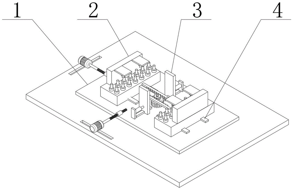
FIG. 1 is a schematic view of the overall structure of the present invention;
FIG. 2 is a schematic structural view of a universal adjusting base device according to the present invention;
FIG. 3 is a schematic view of a stable multi-point support apparatus according to the present invention;
FIG. 4 is a schematic structural view of a four-way adjusting fixing device of the present invention.
In the figure: 1-universal adjusting base device, 101-bottom plate, 102-sliding plate, 103-driving adjusting motor, 104-threaded rod, 105-threaded sleeve, 2-stable multi-point supporting device, 201-base, 202-first hydraulic telescopic rod, 203-second hydraulic telescopic rod, 204-top plate, 3-four-direction adjusting fixing device, 301-adjusting fixing motor, 302-gear, 303-rack, 304-second sliding rail, 305-extrusion plate, 306-supporting plate, 307-third hydraulic telescopic rod and 4-first sliding rail.
Detailed Description
Example 1: referring to fig. 1-4, the present invention provides a technical solution:
a positioning device for automobile stamping parts comprises a universal adjusting base device 1, a stable multi-point supporting device 2 and a four-way adjusting and fixing device 3, wherein the top end surface of the universal adjusting base device 1 is fixedly connected with first slide rails 4 which are arranged in a bilateral symmetry manner, the number of the first slide rails 4 is 2, the number of each group of the first slide rails 4 is 2, the stable multi-point supporting device 2 is arranged right above the first slide rails 4, the bottom end surface of the stable multi-point supporting device 2 is connected with the universal adjusting base device 1 in a sliding way through a first slide rail 4, the number of the stable multi-point supporting devices 2 is 2, the stable multi-point supporting devices 2 are arranged symmetrically left and right, a four-way adjusting and fixing device 3 is arranged between the stable multi-point supporting devices 2, the bottom end of the central position of the four-direction adjusting and fixing device 3 is embedded in the inner side of the universal adjusting base device 1, and the front side and the rear side of the four-direction adjusting and fixing device 3 are both connected with the universal adjusting base device 1 in a sliding mode.
The universal adjusting base device 1 comprises a bottom plate 101, a sliding plate 102, a driving adjusting motor 103, a threaded rod 104 and a threaded sleeve 105, wherein the top end face of the bottom plate 101 is slidably connected with the sliding plate 102, the top end face of the bottom plate 101 is fixedly connected with the driving adjusting motor 103, the tail end of a main shaft of the driving adjusting motor 103 is fixedly connected with the threaded rod 104, the outer side of the threaded rod 104 is spirally connected with the threaded sleeve 105, the bottom end of the threaded sleeve 105 is fixedly connected with the sliding plate 102, through the arranged universal adjusting base device 1, effective universal adjustment can be better performed on an automobile stamping part fixed on the upper side, so that the position needing stamping is ensured to be positioned under a stamping head, the number of the driving adjusting motors 103 is two, the axial leads of the main shafts of the driving adjusting motors 103 positioned on two sides are vertically arranged, the arrangement is convenient for performing universal adjusting processing on a workpiece, the universal adjustable base device comprises a first hydraulic telescopic rod 202, a second hydraulic telescopic rod 203 and a top plate 204, the top end of the universal adjustable base device 1 is slidably connected with a base 201, the first hydraulic telescopic rod 202 is embedded in one side of the top end face of the base 201, the top plate 204 symmetrically arranged front and back is installed on one side of the base 201, the second hydraulic telescopic rod 203 is fixedly connected with the bottom end face of the top plate 204, the number of the first hydraulic telescopic rods 202 on the base 201 on one side is 14, the first hydraulic telescopic rods 202 are uniformly installed on the base 201, the number of the second hydraulic telescopic rods 203 on one side is 2, through the stable multi-point supporting device 2, multi-point supporting can be effectively carried out on the special-shaped automobile stamping part, the supporting effect of the automobile stamping part is effectively guaranteed, the automobile stamping part is further guaranteed not to deform and damage during stamping, the four-direction adjusting and fixing device 3 comprises an adjusting and fixing motor 301, A gear 302, a rack 303, a second slide rail 304, an extrusion plate 305, a support plate 306 and a third hydraulic telescopic rod 307, wherein an adjusting fixed motor 301 is embedded at the inner side of the central position of the top end face of the universal adjusting base device 1, the end of a main shaft of the adjusting fixed motor 301 is fixedly connected with the gear 302, one side of the gear 302 is engaged with the rack 303, one side of the rack 303 is fixedly connected with the stable multipoint support device 2, the top end face of the universal adjusting base device 1 is slidably connected with the extrusion plate 305, one side of the extrusion plate 305 is fixedly connected with the third hydraulic telescopic rod 307, the other end of the third hydraulic telescopic rod 307 is fixedly connected with the support plate 306, the bottom end of the support plate 306 is fixedly connected with the universal adjusting base device 1, the bottom end of the extrusion plate 305 is slidably connected with the second slide rail 304, the second slide rail 304 is perpendicular to the extrusion plate 305, and the, fixing device 3 is adjusted through the quadriversal that sets up, can be effectual carry out stable fixed before the stamping of automobile punching part to guarantee that automobile punching part can not take place to remove, guarantee the accuracy of punching a hole.
The using method comprises the following steps: the device is connected with an external power supply before use, firstly, a workpiece is placed between a stable multipoint supporting device 2 and an adjusting and fixing motor 3, then the adjusting and fixing motor 301 is started, then the stable multipoint supporting devices 2 on two sides are driven to slide on a universal adjusting base device 1 through a first slide rail 4 under the action of a gear 302 and a rack 303, meanwhile, a third hydraulic telescopic rod 307 extends, so that the effect of limiting and clamping the workpiece is realized under the action of a supporting plate 306, a second slide rail 304 and an extrusion plate 305, the first hydraulic telescopic rods 202 and the second hydraulic telescopic rods 203 are started, the first hydraulic telescopic rods 202 arranged in an array mode can better support the bottom end face of a special-shaped part, then the second hydraulic telescopic rods 203 on the top can better support and fix the special-shaped workpiece, the better fixing effect is ensured, then the rotation of the adjusting motor 103 is driven and driven according to the position of a punch and the position to be punched, the slide plate 102 is then moved by the action of the threaded rod 104 and the threaded sleeve 105 to facilitate the punching process on the workpiece.
The principles and embodiments of the present invention are explained herein using specific examples, which are presented only to assist in understanding the method and its core concepts of the present invention. The foregoing is only a preferred embodiment of the present invention, and it should be noted that there are objectively infinite specific structures due to the limited character expressions, and it will be apparent to those skilled in the art that a plurality of modifications, decorations or changes may be made without departing from the principle of the present invention, and the technical features described above may be combined in a suitable manner; such modifications, variations, combinations, or adaptations of the invention using its spirit and scope, as defined by the claims, may be directed to other uses and embodiments.

Claims (8)

1.一种汽车冲压件定位装置,包括万向调节底座装置(1)、稳定多点支撑装置(2)和四向调节固定装置(3),其特征在于:所述万向调节底座装置(1)的顶端面固定连接有呈左右对称设置的第一滑轨(4),所述第一滑轨(4)的数量为2组,每组所述第一滑轨(4)的数量为2个,所述第一滑轨(4)的正上方设有稳定多点支撑装置(2),且稳定多点支撑装置(2)的底端面通过第一滑轨(4)与万向调节底座装置(1)滑动连接,所述稳定多点支撑装置(2)的数量为2个,且稳定多点支撑装置(2)呈左右对称设置,所述稳定多点支撑装置(2)之间设有四向调节固定装置(3),且四向调节固定装置(3)的中央位置底端嵌设在万向调节底座装置(1)的内侧,所述四向调节固定装置(3)的前后两侧均与万向调节底座装置(1)滑动连接。1. An automobile stamping part positioning device, comprising a universal adjustment base device (1), a stable multi-point support device (2) and a four-way adjustment fixing device (3), characterized in that: the universal adjustment base device ( The top surface of 1) is fixedly connected with first slide rails (4) arranged symmetrically on the left and right, the number of the first slide rails (4) is 2 groups, and the number of the first slide rails (4) in each group is 2, a stable multi-point support device (2) is provided directly above the first slide rail (4), and the bottom end face of the stable multi-point support device (2) is universally adjusted through the first slide rail (4) The base device (1) is slidably connected, the number of the stable multi-point support devices (2) is 2, and the stable multi-point support devices (2) are arranged symmetrically on the left and right, and between the stable multi-point support devices (2) A four-way adjusting fixing device (3) is provided, and the bottom end of the central position of the four-way adjusting fixing device (3) is embedded in the inner side of the universal adjusting base device (1). Both the front and rear sides are slidably connected with the universal adjustment base device (1). 2.根据权利要求1所述的一种汽车冲压件定位装置,其特征在于:万向调节底座装置(1)包括底板(101)、滑动板(102)、驱动调节电机(103)、螺纹杆(104)和螺纹套筒(105),所述底板(101)的顶端面滑动连接有滑动板(102),所述底板(101)的顶端面固定连接有驱动调节电机(103),所述驱动调节电机(103)的主轴末端固定连接有螺纹杆(104),所述螺纹杆(104)的外侧螺旋连接有螺纹套筒(105),且螺纹套筒(105)的底端与滑动板(102)固定连接。2. An automobile stamping part positioning device according to claim 1, characterized in that: the universal adjustment base device (1) comprises a bottom plate (101), a sliding plate (102), a drive adjustment motor (103), a threaded rod (104) and a threaded sleeve (105), a sliding plate (102) is slidably connected to the top surface of the bottom plate (101), and a drive adjusting motor (103) is fixedly connected to the top surface of the bottom plate (101). A threaded rod (104) is fixedly connected to the end of the main shaft of the driving adjustment motor (103), and a threaded sleeve (105) is threadedly connected to the outer side of the threaded rod (104), and the bottom end of the threaded sleeve (105) is connected to the sliding plate (102) Fixed connection. 3.根据权利要求2所述的一种汽车冲压件定位装置,其特征在于:所述驱动调节电机(103)的数量为两个,且位于两侧的所述驱动调节电机(103)的主轴的轴心线呈垂直设置。3. An automobile stamping part positioning device according to claim 2, characterized in that: the number of the drive adjustment motors (103) is two, and the main shafts of the drive adjustment motors (103) are located on both sides The axis line is set vertically. 4.根据权利要求1所述的一种汽车冲压件定位装置,其特征在于:所述稳定多点支撑装置(2)包括底座(201)、第一液压伸缩杆(202)、第二液压伸缩杆(203)和顶板(204),所述万向调节底座装置(1)的顶端滑动连接有底座(201),所述底座(201)的顶端面一侧嵌设有第一液压伸缩杆(202),所述底座(201)的一侧安装有呈前后对称设置的顶板(204),所述顶板(204)的底端面固定连接有第二液压伸缩杆(203)。4 . The positioning device for automobile stamping parts according to claim 1 , wherein the stable multi-point support device ( 2 ) comprises a base ( 201 ), a first hydraulic telescopic rod ( 202 ), a second hydraulic telescopic rod ( 202 ). Rod (203) and top plate (204), a base (201) is slidably connected to the top of the universal adjustment base device (1), and a first hydraulic telescopic rod ( 202), one side of the base (201) is installed with a top plate (204) symmetrically arranged front and rear, and a second hydraulic telescopic rod (203) is fixedly connected to the bottom end surface of the top plate (204). 5.根据权利要求4所述的一种汽车冲压件定位装置,其特征在于:位于一侧的所述底座(201)上的第一液压伸缩杆(202)的数量为14个,且第一液压伸缩杆(202)均匀的安装在底座(201)上,位于一侧的所述第二液压伸缩杆(203)的数量为2个。5. The automobile stamping part positioning device according to claim 4, wherein the number of the first hydraulic telescopic rods (202) located on the base (201) on one side is 14, and the first The hydraulic telescopic rods (202) are evenly installed on the base (201), and the number of the second hydraulic telescopic rods (203) located on one side is two. 6.根据权利要求1所述的一种汽车冲压件定位装置,其特征在于:所述四向调节固定装置(3)包括调节固定电机(301)、齿轮(302)、齿条(303)、第二滑轨(304)、挤压板(305)、支撑板(306)和第三液压伸缩杆(307),所述万向调节底座装置(1)的顶端面中央位置处内侧嵌设有调节固定电机(301),所述调节固定电机(301)的主轴末端固定连接有齿轮(302),所述齿轮(302)的一侧啮合有齿条(303),所述齿条(303)的一侧与稳定多点支撑装置(2)固定连接,所述万向调节底座装置(1)的顶端面滑动连接有挤压板(305),所述挤压板(305)的一侧固定连接有第三液压伸缩杆(307),所述第三液压伸缩杆(307)的另一端固定连接有支撑板(306),所述支撑板(306)的底端与万向调节底座装置(1)固定连接。6 . The positioning device for automobile stamping parts according to claim 1 , wherein the four-way adjusting and fixing device ( 3 ) comprises an adjusting and fixing motor ( 301 ), a gear ( 302 ), a rack ( 303 ), 6 . The second slide rail (304), the pressing plate (305), the supporting plate (306) and the third hydraulic telescopic rod (307), the universal adjustment base device (1) is embedded in the center position of the top end surface of the inner side A fixed motor (301) is adjusted, a gear (302) is fixedly connected to the end of the main shaft of the fixed motor (301), a rack (303) is engaged with one side of the gear (302), and the rack (303) One side is fixedly connected with the stable multi-point support device (2), the top surface of the universal adjustment base device (1) is slidably connected with a pressing plate (305), and one side of the pressing plate (305) is fixed A third hydraulic telescopic rod (307) is connected, the other end of the third hydraulic telescopic rod (307) is fixedly connected with a support plate (306), and the bottom end of the support plate (306) is connected to the universal adjustment base device ( 1) Fixed connection. 7.根据权利要求6所述的一种汽车冲压件定位装置,其特征在于:所述挤压板(305)的底端滑动连接有第二滑轨(304),且第二滑轨(304)的垂直于挤压板(305),所述第二滑轨(304)的底端与万向调节底座装置(1)固定连接。7 . The positioning device for automobile stamping parts according to claim 6 , wherein the bottom end of the extrusion plate ( 305 ) is slidably connected with a second slide rail ( 304 ), and the second slide rail ( 304 ) is slidably connected with the second slide rail ( 304 ). ) is perpendicular to the pressing plate (305), and the bottom end of the second sliding rail (304) is fixedly connected with the universal adjustment base device (1). 8.根据权利要求1所述的一种汽车冲压件定位装置及其使用方法,其特征在于:包括以下使用步骤:8. A kind of automobile stamping part positioning device and using method thereof according to claim 1, is characterized in that: comprise the following using steps: 步骤一:限位夹持:首先将工件放置到稳定多点支撑装置(2)和调节固定电机(3)之间,然后启动调节固定电机(301),然后在齿轮(302)和齿条(303)的作用下带动两侧的稳定多点支撑装置(2)通过第一滑轨(4)在万向调节底座装置(1)上滑动,同时第三液压伸缩杆(307)伸长,从而在支撑板(306)、第二滑轨(304)和挤压板(305)的作用下,实现限位夹持工件的效果;Step 1: Limit clamping: first place the workpiece between the stable multi-point support device (2) and the adjusting and fixing motor (3), then start the adjusting and fixing motor (301), and then connect the gear (302) and rack ( Under the action of 303), the stable multi-point support devices (2) on both sides are driven to slide on the universal adjustment base device (1) through the first slide rail (4), and at the same time, the third hydraulic telescopic rod (307) is extended, thereby Under the action of the support plate (306), the second slide rail (304) and the pressing plate (305), the effect of clamping the workpiece in a limited position is achieved; 步骤二:多点支撑固定:在步骤一之后,启动第一液压伸缩杆(202)和第二液压伸缩杆(203),阵列式设置的第一液压伸缩杆(202),可以较好的对异形件的底端面进行较好的支撑,然后在顶部的第二液压伸缩杆(203)的作用下,可以实现对异形工件的较好的支撑固定,保证了较好的固定效果;Step 2: Multi-point support and fixation: After step 1, the first hydraulic telescopic rod (202) and the second hydraulic telescopic rod (203) are activated, and the arrayed first hydraulic telescopic rod (202) can better The bottom end face of the special-shaped part is better supported, and then under the action of the second hydraulic telescopic rod (203) on the top, better support and fixation of the special-shaped workpiece can be achieved, ensuring a better fixing effect; 步骤三:位置调节处理:然后根据需要打孔的位置与冲头的位置控制驱动调节电机(103)的转动,然后通过螺纹杆(104)与螺纹套筒(105)的作用带动滑动板(102)的移动,进而便于对工件进行打孔处理。Step 3: Position adjustment processing: then control the rotation of the driving adjustment motor (103) according to the required punching position and the position of the punch, and then drive the sliding plate (102) through the action of the threaded rod (104) and the threaded sleeve (105). ) movement to facilitate the drilling of the workpiece.
CN202010874182.0A 2020-08-26 2020-08-26 A positioning device for automobile stamping parts and its use method Active CN112222309B (en)

Priority Applications (1)

Application Number Priority Date Filing Date Title
CN202010874182.0A CN112222309B (en) 2020-08-26 2020-08-26 A positioning device for automobile stamping parts and its use method

Applications Claiming Priority (1)

Application Number Priority Date Filing Date Title
CN202010874182.0A CN112222309B (en) 2020-08-26 2020-08-26 A positioning device for automobile stamping parts and its use method

Publications (2)

Publication Number Publication Date
CN112222309A true CN112222309A (en) 2021-01-15
CN112222309B CN112222309B (en) 2023-11-10

Family

ID=74116922

Family Applications (1)

Application Number Title Priority Date Filing Date
CN202010874182.0A Active CN112222309B (en) 2020-08-26 2020-08-26 A positioning device for automobile stamping parts and its use method

Country Status (1)

Country Link
CN (1) CN112222309B (en)

Cited By (1)

* Cited by examiner, † Cited by third party
Publication number Priority date Publication date Assignee Title
CN119076768A (en) * 2024-10-31 2024-12-06 浙江中维建筑工程设计有限公司 A kind of auxiliary pressing device for punching aluminum plate of building facade

Citations (9)

* Cited by examiner, † Cited by third party
Publication number Priority date Publication date Assignee Title
KR200320307Y1 (en) * 2003-04-29 2003-07-22 이원복 The fixing apparatus for industrial process stuff
CN207578248U (en) * 2017-12-05 2018-07-06 苏州斯塔迪自动化科技有限公司 A kind of automobile supporting plate automatically controls fixture
CN207787428U (en) * 2018-01-23 2018-08-31 东莞市伟峰印刷有限公司 A kind of solid state disk stamping punch die
CN209502760U (en) * 2019-01-21 2019-10-18 西安航空学院 A positioning mold base for stamping the extension part of the automobile floor beam
CN110405095A (en) * 2019-08-27 2019-11-05 徐海东 A kind of fast-positioning device of heavy truck automobile gearbox gear punching structure
CN210551003U (en) * 2019-07-30 2020-05-19 黄骅渤海机械制造有限公司 High security C type table
CN111283140A (en) * 2020-03-03 2020-06-16 江苏新中洲特种合金材料有限公司 Precision casting wax blank processing technology
CN210998472U (en) * 2019-09-11 2020-07-14 苏州凯德旺精密测试设备有限公司 A pressfitting tool for irregular part
CN211249250U (en) * 2019-11-14 2020-08-14 沈阳东荣机械有限公司 Planer-type milling machine positioning adds clamping apparatus

Patent Citations (9)

* Cited by examiner, † Cited by third party
Publication number Priority date Publication date Assignee Title
KR200320307Y1 (en) * 2003-04-29 2003-07-22 이원복 The fixing apparatus for industrial process stuff
CN207578248U (en) * 2017-12-05 2018-07-06 苏州斯塔迪自动化科技有限公司 A kind of automobile supporting plate automatically controls fixture
CN207787428U (en) * 2018-01-23 2018-08-31 东莞市伟峰印刷有限公司 A kind of solid state disk stamping punch die
CN209502760U (en) * 2019-01-21 2019-10-18 西安航空学院 A positioning mold base for stamping the extension part of the automobile floor beam
CN210551003U (en) * 2019-07-30 2020-05-19 黄骅渤海机械制造有限公司 High security C type table
CN110405095A (en) * 2019-08-27 2019-11-05 徐海东 A kind of fast-positioning device of heavy truck automobile gearbox gear punching structure
CN210998472U (en) * 2019-09-11 2020-07-14 苏州凯德旺精密测试设备有限公司 A pressfitting tool for irregular part
CN211249250U (en) * 2019-11-14 2020-08-14 沈阳东荣机械有限公司 Planer-type milling machine positioning adds clamping apparatus
CN111283140A (en) * 2020-03-03 2020-06-16 江苏新中洲特种合金材料有限公司 Precision casting wax blank processing technology

Cited By (1)

* Cited by examiner, † Cited by third party
Publication number Priority date Publication date Assignee Title
CN119076768A (en) * 2024-10-31 2024-12-06 浙江中维建筑工程设计有限公司 A kind of auxiliary pressing device for punching aluminum plate of building facade

Also Published As

Publication number Publication date
CN112222309B (en) 2023-11-10

Similar Documents

Publication Publication Date Title
CN107378378B (en) Press-fitting and welding integrated device for gravure roller
CN112355349A (en) Machining device for multi-station forklift wheels
CN110238657A (en) EPS autobalance drilling pin pressing machine
CN221658463U (en) Automobile seat framework mounting and positioning mechanism
CN201807740U (en) Slender shaft part automatic processing equipment
CN109605496A (en) A punching device for furniture board
CN206550693U (en) A kind of bonnet fixture
CN206046785U (en) A kind of bed-table steel pipe automatic punch machine
CN112222309B (en) A positioning device for automobile stamping parts and its use method
CN214722511U (en) Internal stay anchor clamps are used in motor housing processing
CN111360178B (en) Rotary driving device for probe bending
CN102152137B (en) Method for processing part by using support device
CN216370992U (en) A control arm assembly device
CN217570958U (en) Bearing hole machining device
CN210453093U (en) Bamboo tube punching equipment for bamboo product processing
CN214639531U (en) Punching device is used in saddle mounting panel production
CN111496149B (en) Double-bending machine for probe
CN222344794U (en) Machine tool workbench for rapidly positioning shaft parts
CN210523500U (en) Automobile instrument desk tubular beam frock support
CN206436010U (en) The power adaptability flexible fixture processed for thin-wall rotation-type part
CN222043303U (en) Slewing bearing ring heat treatment correction equipment
CN220092920U (en) Cylinder forging of single-cylinder hydraulic cone machine
CN223476079U (en) Hardware fitting punching ear hole die
CN212635014U (en) Workpiece fixing device for machining automobile engine gear
CN224075108U (en) Positioning, limiting and guiding device of press

Legal Events

Date Code Title Description
PB01 Publication
PB01 Publication
SE01 Entry into force of request for substantive examination
GR01 Patent grant
GR01 Patent grant