Background
When the width of a bridge is too large, a steel box girder structure is generally adopted, welding construction needs to be carried out on a joint after the bridge steel box girders are assembled and spliced in place, and at present, a lift truck or a scaffold platform is mostly adopted for welding operation, so that the traffic pressure on the ground is increased, the workload and the construction cost of auxiliary facilities are greatly increased, and certain potential safety hazards exist in the construction of an overhead welding platform, so that the construction operation efficiency is reduced; if the bridge is a sea-crossing bridge, construction cannot be carried out through a lift truck or a scaffold.
Disclosure of Invention
The invention aims to provide a telescopic rail type bridge construction auxiliary device which can overcome the defects in the prior art, so that the practicability of equipment is improved.
The technical scheme adopted by the invention for solving the technical problems is as follows: the invention relates to a telescopic rail type bridge construction auxiliary device, which comprises two weight boxes which are arranged symmetrically at left and right, wherein the upper end surfaces of the weight boxes are fixedly connected with an auxiliary connecting block which extends to the side far away from the symmetrical center, the right side of the upper end surface of a foundation plate is fixedly connected with an auxiliary connecting block, an auxiliary plate is hinged on the auxiliary connecting block, a steel cable cavity is arranged in the auxiliary plate, the side of the auxiliary plate far away from the symmetrical center is provided with a main box body, a second motor cavity is arranged in the main box body, the front side and the back side of the second motor cavity at the left side are symmetrically provided with two connecting block cavities with outward openings, a connecting block which extends to the outside far away from the second motor cavity side is connected in a sliding fit manner in the connecting block cavity, the side of the connecting block far away from the second motor cavity is fixedly connected with a first rail, second threaded rod downside fixedly connected with fourth gear, left side end wall just is located under the second motor chamber second threaded rod front side fixedly connected with second motor, second motor up end fixedly connected with second worm, spline fit is connected with the sleeve on the second worm, sleeve upside fixedly connected with second gear, the annular is equipped with on the sleeve and is located the sleeve ring chamber of second gear downside, left side second motor chamber right side end wall fixedly connected with driving lever stopper, be equipped with the opening forward in the driving lever stopper with the front side connecting block chamber intercommunication and backward and left side the driving lever chamber of second motor chamber intercommunication, fixedly connected with offsets the piece in the driving lever chamber right side end wall, offset the piece be equipped with the opening forward and with the front side offset the piece chamber of connecting block chamber intercommunication, sliding fit is connected to backward extend to with sleeve ring chamber sliding fit is connected and extend forward and with the driving lever chamber sliding fit is connected Offset a rear end wall fixed connection's driving lever, offset a intracavity sliding fit and be connected with and extend to the front side forward the round pin of stirring in the connecting block intracavity, fixedly connected with is located on the sleeve ring chamber downside and can with fourth gear engagement's third gear, the left side it is connected with to rotate between the lower extreme wall on the second motor and is located the second motor with the first worm between the driving lever stopper.
On the basis of the technical scheme, an eighth gear capable of being meshed with the second gear is fixedly connected to the first worm on the left side on the deflector rod cavity, a second connecting rod which is located on the eighth gear and extends leftwards is connected to the right end wall of the second motor cavity in a rotating fit manner, the second connecting rod is located on the second connecting rod and is capable of being meshed with the left end face of the second worm, a fifth gear is fixedly connected between the second worm and the first worm, a second worm wheel capable of being meshed with the second worm is fixedly connected to the rear side of the second connecting rod located on the fifth gear, a third motor is fixedly connected to the lower end wall of the second motor cavity on the right side, the upper end face of the third motor can be fixedly connected with the lower end face of the first worm, and a rope disc is fixedly connected to the first worm on the right side on the upper side of the third motor, the last winding of rope reel has the rope, second motor chamber right side end wall normal running fit is connected with and extends to left the second motor intracavity and extend to the first connecting rod in the cable wire intracavity right side, the terminal fixedly connected with in first connecting rod left side can with first worm wheel and the terminal fixedly connected with cable wire in right side of first worm rear end face thread engagement.
On the basis of the technical scheme, the rear side fixedly connected with extends forward in the connecting block and runs through second motor chamber to front side gag lever post in the connecting block, fixedly connected with can with the screw thread piece that second threaded rod screw-thread fit connects on the gag lever post, just keep away from in the connecting block the gag lever post side is provided with the ring gear chamber, ring gear intracavity end wall fixedly connected with ring gear, the connecting block is close to second motor chamber end wall just is located gag lever post upside normal running fit is connected with runs through second motor chamber both sides extend to around to the ring gear intracavity third connecting rod, fixedly connected with can with fifth gear engagement's sixth gear on the third connecting rod, both sides end fixedly connected with can with ring gear engagement's seventh gear around the third connecting rod.
On the basis of the technical scheme, be equipped with the track chamber that the opening is decurrent in the first track, track intracavity sliding fit is connected with the second track, be equipped with the ascending screw thread chamber of opening in the second track, first track up end fixedly connected with motor, terminal surface fixedly connected with down extend to the screw thread intracavity under the motor and can with the first threaded rod that screw thread chamber screw-thread fit connects, just be located in the second track the screw thread chamber downside is equipped with controls the spacing chamber that link up, be in the connecting block chamber part is equipped with the decurrent arc chamber of opening.
On the basis of the technical scheme, a rail car cavity positioned on the lower side of the second motor cavity is arranged in the main box body on the right side, a rail car is arranged in the rail car cavity, the other end of the rope extends downwards and can be fixedly connected with the rope, two electromagnet cavities which are positioned on the lower side of the rail car cavity and are symmetrically arranged front and back are arranged in the main box body on the right side, the lower sides of the electromagnet cavities are communicated with a limiting block cavity, electromagnets are fixedly connected in the upper end walls of the electromagnet cavities, limiting blocks are connected in the electromagnet cavities in a sliding fit manner, auxiliary connecting block cavities with upward openings are arranged in the auxiliary connecting blocks, fifth connecting rods which extend to the outside from the front side to the back side are fixedly connected in the auxiliary connecting block cavities in an auxiliary plate and positioned on the lower side of the steel cable cavity, the, the auxiliary plate is fixedly connected with a fixing pin close to the symmetrical center side, and a hydraulic rod hinged with the upper end face of the foundation plate is hinged to the fixing pin.
The invention has the beneficial effects that: this device passes through the master tank body, the connecting block, the structural grouping of first track, lift truck or the scaffold frame that use in having replaced traditional construction, can not occupy the ground lane, and do not increase auxiliary facilities, consequently, obtain fine improvement on work load and construction cost, through the stopper, spacing in spacing chamber, make second track and first track more stable effect, through the railcar at first track, move on the second track, make the workman can accomplish the removal of self and equipment through controlling the railcar, it is more convenient to reach weldment work, the effect of welded quality has been guaranteed.
Detailed Description
The invention will now be described in detail with reference to fig. 1-7, wherein for ease of description the orientations described below are now defined as follows: the up, down, left, right, and front-back directions described below correspond to the up, down, left, right, and front-back directions in the projection relationship of fig. 1 itself.
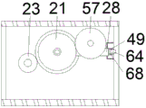
The telescopic rail type bridge construction auxiliary device described in conjunction with the attached drawings 1-7 comprises two weight boxes 54 which are arranged symmetrically left and right, the upper end face of each weight box 54 is fixedly connected with a connecting block 59 which extends towards the side far away from the symmetrical center of the weight box 54, the right side of the upper end face of the base plate 48 is fixedly connected with an auxiliary connecting block 59, the auxiliary connecting block 59 is hinged with an auxiliary plate 52, a steel cable cavity 53 is arranged in the auxiliary plate 52, the side of the auxiliary plate 52 far away from the symmetrical center is provided with a main box body 10, a second motor cavity 30 is arranged in the main box body 10, two connecting block cavities 19 with outward openings are symmetrically arranged in the front and back of the second motor cavity 30 on the left side, the connecting block cavities 19 are connected with connecting blocks 58 which extend to the outside far away from the side of the second motor cavity 30 in a sliding fit manner, the side of the connecting blocks 58 far away from, a second threaded rod 18 extending upwards is connected to the lower end wall of the second motor cavity 30 on the left in a rotating fit manner, a fourth gear 23 is fixedly connected to the lower side of the second threaded rod 18, a second motor 26 is fixedly connected to the lower end wall of the second motor cavity 30 on the left and located on the front side of the second threaded rod 18, a second worm 20 is fixedly connected to the upper end surface of the second motor 26, a sleeve 67 is connected to the second worm 20 in a spline fit manner, a second gear 21 is fixedly connected to the upper side of the sleeve 67, a sleeve ring cavity 25 located on the lower side of the second gear 21 is annularly arranged on the sleeve 67, a shift lever limiting block 56 is fixedly connected to the right end wall of the second motor cavity 30 on the left, a shift lever cavity 55 with an opening forward communicated with the connecting block cavity 19 on the front side and backward communicated with the second motor cavity 30 on the left side is arranged in the shift lever limiting block 56, a cancellation block 49 is fixedly connected to the right, it just with the front side to be equipped with the opening forward in the piece 49 to offset the piece chamber 68 that links up the block chamber 19 intercommunication, the deflector rod intracavity 55 sliding fit is connected to extend backward to with sleeve ring chamber sliding fit is connected and extend forward to with offset the driving lever 27 of piece 49 rear end wall fixed connection, offset piece chamber 68 sliding fit is connected with and extend forward to the front side the stirring round pin 64 in the block chamber 19, fixedly connected with is located on the sleeve 67 sleeve ring chamber 25 downside and can with the third gear 22 of fourth gear 23 meshing, the left side rotating fit is connected with between the end wall about the second motor 30 is located second motor 26 with first worm 37 between the driving lever stopper 56.
In addition, in one embodiment, an eighth gear 57 capable of meshing with the second gear 21 is fixedly connected to the first worm 37 on the left side on the dial rod cavity 55, a second connecting rod 28 extending leftwards on the upper side of the eighth gear 57 and capable of meshing with the left end face of the second worm 20 is connected to the right end wall of the second motor cavity 30 in a rotating fit manner, a fifth gear 29 is fixedly connected to the second connecting rod 28 and between the second worm 20 and the first worm 37, a second worm wheel 77 capable of meshing with the second worm 20 is fixedly connected to the rear side of the fifth gear 29, a third motor 40 is fixedly connected to the lower end wall of the second motor cavity 30 on the right side, the upper end face of the third motor 40 is capable of fixedly connecting with the lower end face of the first worm 37, a rope disc 39 is fixedly connected to the first worm 37 on the right side on the upper side of the third motor 40, the rope disc 39 is wound with a rope 42, the right end wall of the second motor cavity 30 is connected with a first connecting rod 12 which extends leftwards into the second motor cavity 30 and rightwards into the steel rope cavity 53 in a rotating and matching manner, and the left end of the first connecting rod 12 is fixedly connected with a first worm wheel 11 which is in threaded engagement with the rear end face of the first worm 37 and a steel rope 65 which is fixedly connected with the right end of the first worm wheel.
In addition, in one embodiment, a limiting rod 32 extending forwards through the second motor cavity 30 to the front side of the connecting block 58 is fixedly connected in the connecting block 58 at the rear side, a thread block 31 which can be in thread fit connection with the second threaded rod 18 is fixedly connected to the limiting rod 32, a gear ring cavity 66 is arranged in the connecting block 58 and far away from the limiting rod 32, a gear ring 17 is fixedly connected with the inner end wall of the gear ring cavity 66, the connecting block 58 is close to the end wall of the second motor cavity 30 and is positioned at the upper side of the limiting rod 32, and is connected with a third connecting rod 34 which penetrates through the second motor cavity 30 and extends into the gear ring cavity 66 towards the front side and the rear side in a rotating fit manner, a sixth gear 33 capable of meshing with the fifth gear 29 is fixedly connected to the third connecting rod 34, the front and rear ends of the third connecting rod 34 are fixedly connected with seventh gears 35 capable of meshing with the gear ring 17.
In addition, in an embodiment, a track cavity 14 with a forward opening is formed in the first track 36, a second track 62 is connected to the track cavity 14 in a sliding fit manner, a threaded cavity 16 with an upward opening is formed in the second track 62, a first motor 13 is fixedly connected to the upper end face of the first track 36, a first threaded rod 15 which extends downwards into the threaded cavity 16 and can be connected with the threaded cavity 16 in a threaded fit manner is fixedly connected to the lower end face of the first motor 13, a left-right through limiting cavity 24 is formed in the second track 62 and located on the lower side of the threaded cavity 16, and an arc-shaped cavity 47 with a downward opening is formed in the connecting block 58 in the connecting block cavity 19.
In addition, in one embodiment, a railcar cavity 41 located at the lower side of the second motor cavity 30 is arranged in the right main box body 10, a railcar 43 is arranged in the railcar cavity 41, the other end of the rope 42 extends downwards and can be fixedly connected with the rope 43, two electromagnet cavities 63 which are located at the lower side of the railcar cavity 41 and are symmetrically arranged in the front-back direction are arranged in the right main box body 10, a limiting block cavity 44 is communicated with the lower side of the electromagnet cavity 63, an electromagnet 46 is fixedly connected in the upper end wall of the electromagnet cavity 63, a limiting block 45 is connected in the electromagnet cavity 63 in a sliding fit manner, an auxiliary connecting block cavity 60 with an upward opening is arranged in the auxiliary connecting block 59, a fifth connecting rod 61 which extends to the outside from the front side to the back side is fixedly connected in the auxiliary plate 52 and located at the lower side of the rope cavity 53, the front end and back end ends of the fifth connecting rod 61, the auxiliary plate 52 is fixedly connected with a fixing pin 51 near the symmetrical center side, and the fixing pin 51 is hinged with a hydraulic rod 50 hinged with the upper end face of the base plate 48.
The fixing and connecting method in this embodiment includes, but is not limited to, bolting, welding, and the like.
As shown in fig. 1 to 7, in the initial state of the apparatus of the present invention, the base plate 48 is placed horizontally on the cross section of the bridge, the hydraulic rod 50 is in the contracted state, the auxiliary plate 52 and the main tank 10 are in the horizontal state, the first connecting rod 12 is uppermost in the auxiliary plate 52, the connecting block 58 is uppermost in the connecting block chamber 19, the first rail 36 is horizontally placed on both sides of the main tank 10, the stopper 45 is engaged with the electromagnet 46, the second gear 21 is engaged with the eighth gear 57, and the third gear 22 is engaged with the fourth gear 23;
sequence of mechanical actions of the whole device: when the hydraulic rod 50 is extended to enable the auxiliary plate 52 to rotate around the auxiliary connecting block cavity 60 to be vertical to the bridge floor, at the moment, the second motor 26 is started, the second motor 26 rotates to drive the sleeve 67 to rotate through the second worm 20, the sleeve 67 rotates to drive the eighth gear 57 to rotate through the second gear 21, the eighth gear 57 rotates to drive the first worm wheel 11 to rotate through the first worm 37, the first worm wheel 11 rotates to drive the first connecting rod 12 to rotate, the main box body 10 moves downwards under the action of the steel cable 65, meanwhile, the sleeve 67 rotates to drive the fourth gear 23 to rotate through the third gear 22, and the fourth gear 23 rotates to drive the thread block 31 to move downwards through the second threaded rod 18; the screw block 31 moves downwards to drive the connecting block 58 to move downwards through the limiting rod 32, when the connecting block 58 descends to the lowest point, the sixth gear 33 is just meshed with the fifth gear 29, the second worm 20 rotates to drive the second connecting rod 28 to rotate through the second worm wheel 77, the second connecting rod 28 rotates to drive the fifth gear 29 to rotate, the fifth gear 29 rotates to drive the third connecting rod 34 to rotate through the sixth gear 33, the third connecting rod 34 rotates to drive the connecting block 58 to rotate upwards around the limiting rod 32 through the seventh gear 35, the connecting block 58 drives the first rail 36 to rotate together, the toggle pin 64 just enters the arc-shaped cavity 47, the toggle pin 64 is displaced under the action of the arc-shaped cavity 47, the toggle pin 64 moves to drive the toggle rod 27 to move upwards through the offsetting block cavity 68, the toggle rod 27 moves upwards to drive the second gear 21 and the third gear 22 to move upwards through the sleeve 67, so that the second gear 21 is disengaged from the eighth gear 57 and the third gear 22 is disengaged from the fourth gear 23; when the first rail 36 rotates to be parallel to the bridge floor, the second motor 26 stops rotating, the first motor 13 is started to drive the first threaded rod 15 to rotate, the first threaded rod 15 rotates to enable the second rail 62 to move rightwards, when the second rail 62 moves into the limiting block cavity 44, the first motor 13 stops rotating, the third motor 40 is started to drive the first worm 37 to rotate, the first worm 37 rotates to drive the first connecting rod 12 to rotate through the first worm wheel 11, the first connecting rod 12 rotates to enable the right main box body 10 to move downwards under the action of the steel cable 65, the first worm 37 rotates to drive the rope disc 39 to rotate, the rope disc 39 rotates to drive the rail car 43 to move downwards through the rope 42, when the right main box body 10 moves to the lowest point, the third motor 40 is powered off, the electromagnet 46 is powered off, the limiting block 45 moves downwards into the limiting cavity 24, and the second rail 62 is more stable, the rail car 43 is disconnected from the rope 42 by the worker's operation and freely moves along the first and second rails 36 and 62.
The invention has the beneficial effects that: this device passes through the master tank body, the connecting block, the structural grouping of first track, lift truck or the scaffold frame that use in having replaced traditional construction, can not occupy the ground lane, and do not increase auxiliary facilities, consequently, obtain fine improvement on work load and construction cost, through the stopper, spacing in spacing chamber, make second track and first track more stable effect, through the railcar at first track, move on the second track, make the workman can accomplish the removal of self and equipment through controlling the railcar, it is more convenient to reach weldment work, the effect of welded quality has been guaranteed.
The above embodiments are merely illustrative of the technical ideas and features of the present invention, and the purpose thereof is to enable those skilled in the art to understand the contents of the present invention and implement the present invention, and not to limit the protection scope of the present invention. All equivalent changes and modifications made according to the spirit of the present invention should be covered within the protection scope of the present invention.