CN112125446A - Tap water purification sedimentation tank and purification method thereof - Google Patents
Tap water purification sedimentation tank and purification method thereof Download PDFInfo
- Publication number
- CN112125446A CN112125446A CN202011076302.9A CN202011076302A CN112125446A CN 112125446 A CN112125446 A CN 112125446A CN 202011076302 A CN202011076302 A CN 202011076302A CN 112125446 A CN112125446 A CN 112125446A
- Authority
- CN
- China
- Prior art keywords
- water
- tank
- fixed
- top end
- precipitation
- Prior art date
- Legal status (The legal status is an assumption and is not a legal conclusion. Google has not performed a legal analysis and makes no representation as to the accuracy of the status listed.)
- Pending
Links
- 238000004062 sedimentation Methods 0.000 title claims abstract description 80
- 238000000746 purification Methods 0.000 title claims abstract description 43
- 239000008399 tap water Substances 0.000 title claims abstract description 43
- 235000020679 tap water Nutrition 0.000 title claims abstract description 43
- 238000000034 method Methods 0.000 title claims abstract description 21
- XLYOFNOQVPJJNP-UHFFFAOYSA-N water Substances O XLYOFNOQVPJJNP-UHFFFAOYSA-N 0.000 claims abstract description 177
- 239000012535 impurity Substances 0.000 claims abstract description 31
- 238000001556 precipitation Methods 0.000 claims abstract description 29
- 238000003860 storage Methods 0.000 claims abstract description 26
- 239000003814 drug Substances 0.000 claims abstract description 20
- 238000005086 pumping Methods 0.000 claims abstract description 19
- 238000002347 injection Methods 0.000 claims abstract description 15
- 239000007924 injection Substances 0.000 claims abstract description 15
- 238000003756 stirring Methods 0.000 claims abstract description 14
- 239000010802 sludge Substances 0.000 claims abstract description 9
- 230000005484 gravity Effects 0.000 claims abstract description 6
- 239000010865 sewage Substances 0.000 claims description 52
- 239000007921 spray Substances 0.000 claims description 20
- 238000005507 spraying Methods 0.000 claims description 7
- 238000001914 filtration Methods 0.000 claims description 6
- 230000008878 coupling Effects 0.000 claims 1
- 238000010168 coupling process Methods 0.000 claims 1
- 238000005859 coupling reaction Methods 0.000 claims 1
- 239000000463 material Substances 0.000 abstract description 15
- 230000000694 effects Effects 0.000 abstract description 6
- 230000001174 ascending effect Effects 0.000 abstract description 3
- 239000013049 sediment Substances 0.000 description 7
- 238000004140 cleaning Methods 0.000 description 6
- 238000004519 manufacturing process Methods 0.000 description 2
- 230000009286 beneficial effect Effects 0.000 description 1
- 238000006243 chemical reaction Methods 0.000 description 1
- 238000010586 diagram Methods 0.000 description 1
- 238000005516 engineering process Methods 0.000 description 1
- 238000005189 flocculation Methods 0.000 description 1
- 230000016615 flocculation Effects 0.000 description 1
- 238000011010 flushing procedure Methods 0.000 description 1
- 239000003673 groundwater Substances 0.000 description 1
- 239000007788 liquid Substances 0.000 description 1
- 238000002156 mixing Methods 0.000 description 1
- 239000002244 precipitate Substances 0.000 description 1
- 230000000630 rising effect Effects 0.000 description 1
- 239000000243 solution Substances 0.000 description 1
Images

Classifications
-
- C—CHEMISTRY; METALLURGY
- C02—TREATMENT OF WATER, WASTE WATER, SEWAGE, OR SLUDGE
- C02F—TREATMENT OF WATER, WASTE WATER, SEWAGE, OR SLUDGE
- C02F9/00—Multistage treatment of water, waste water or sewage
-
- C—CHEMISTRY; METALLURGY
- C02—TREATMENT OF WATER, WASTE WATER, SEWAGE, OR SLUDGE
- C02F—TREATMENT OF WATER, WASTE WATER, SEWAGE, OR SLUDGE
- C02F1/00—Treatment of water, waste water, or sewage
- C02F1/001—Processes for the treatment of water whereby the filtration technique is of importance
-
- C—CHEMISTRY; METALLURGY
- C02—TREATMENT OF WATER, WASTE WATER, SEWAGE, OR SLUDGE
- C02F—TREATMENT OF WATER, WASTE WATER, SEWAGE, OR SLUDGE
- C02F1/00—Treatment of water, waste water, or sewage
- C02F1/52—Treatment of water, waste water, or sewage by flocculation or precipitation of suspended impurities
- C02F1/5281—Installations for water purification using chemical agents
-
- C—CHEMISTRY; METALLURGY
- C02—TREATMENT OF WATER, WASTE WATER, SEWAGE, OR SLUDGE
- C02F—TREATMENT OF WATER, WASTE WATER, SEWAGE, OR SLUDGE
- C02F1/00—Treatment of water, waste water, or sewage
- C02F2001/007—Processes including a sedimentation step
-
- C—CHEMISTRY; METALLURGY
- C02—TREATMENT OF WATER, WASTE WATER, SEWAGE, OR SLUDGE
- C02F—TREATMENT OF WATER, WASTE WATER, SEWAGE, OR SLUDGE
- C02F2103/00—Nature of the water, waste water, sewage or sludge to be treated
- C02F2103/02—Non-contaminated water, e.g. for industrial water supply
Abstract
The invention discloses a tap water purification sedimentation tank and a purification method thereof, wherein the tap water purification sedimentation tank comprises a support bottom plate, one side of the top end of the support bottom plate is provided with a treatment box, the interior of the treatment box is movably connected with a stirring shaft, the top end of one side of the treatment box is fixedly provided with a medicine injection port, and one side of a material pumping pump is provided with a conveying pipe. The invention improves the precipitation efficiency of the precipitation tank by arranging the precipitation structure, the material pumping pump can convey water in the treatment tank to the interior of the precipitation tank for precipitation treatment by starting the material pumping pump, suspended impurities in the water can be precipitated in the inclined plate by the inclined plate, the water flows upwards along the inclined plate, the water collecting tank can collect the ascending water at the moment, the separated impurities slide downwards to the bottom of the precipitation bucket along the inclined plate under the action of gravity and are discharged into the interior of the dirt collection tank by the sludge discharge pipe, the clear water gradually rises to the water outlet tank and is discharged into the water storage tank, the precipitation efficiency of the precipitation tank can be improved by arranging the inclined plate, and further the tap water purification effect is improved.
Description
Technical Field
The invention relates to the technical field of water treatment equipment, in particular to a tap water purification sedimentation tank and a purification method thereof.
Background
Along with the rapid development of national economy, the economic level is continuously improved, the problem of river pollution in China is more and more serious, the water quality of a water body is continuously worsened, most rivers are reduced to three, four or even lower standards from the first and second ground water quality standards of the past country, so that heavy burden is brought to tap water production enterprises in cities taking the rivers as water sources, and new challenges are provided for the tap water production enterprises at the same time, the pollution of the water sources causes certain difficulty for the traditional water purification process, in various water treatment processes such as tap water purification and the like, the process mainly comprises a liquid medicine mixing process, a flocculation reaction process, precipitation, filtration and the like, wherein the precipitation process is completed in a precipitation tank, so that a special tap water purification precipitation tank and a purification method thereof are used;
however, when the existing tap water purifying and settling tank and the existing tap water purifying and settling method are used, the settling tank has low settling efficiency and slow settling speed, and further the tap water purifying effect is reduced, so a tap water purifying and settling tank and a tap water purifying and settling method are developed to solve the problems.
Disclosure of Invention
The invention aims to provide a tap water purification sedimentation tank and a purification method thereof, and aims to solve the problems that the sedimentation tank in the background technology is low in sedimentation efficiency and low in sedimentation speed, and further the tap water purification effect is reduced.
In order to achieve the purpose, the invention provides the following technical scheme: a tap water purifying sedimentation tank and a purifying method thereof comprise a supporting bottom plate, wherein a processing box is arranged on one side of the top end of the supporting bottom plate, a stirring shaft is movably connected inside the processing box, a medicine injection port is fixed on the top end of one side of the processing box, a filtering plate is arranged on the top end of the inside of the processing box, a water injection port is fixed on one side of the top end of the processing box, a servo motor is arranged on the top end of the processing box, the output end of the servo motor is fixedly connected with the stirring shaft through a coupler, a supporting frame is fixed on the top end of the supporting bottom plate, a sedimentation structure is arranged on the top end of the inside of the supporting frame, the sedimentation structure comprises a sedimentation box, the sedimentation box is arranged on the top end of the inside of the supporting frame, an inclined plate is arranged inside the sedimentation box, water collecting grooves are, one side of the water outlet groove is fixedly connected with one side of the water outlet pipe, the bottom end of the inclined plate is fixedly provided with a spoiler, the bottom ends of the settling tanks are fixedly provided with settling hoppers, the bottom ends of the settling hoppers are fixedly provided with sludge discharge pipes, the other side inside the settling tank is provided with a rectifying plate, the top end of the other side of the settling tank is fixedly provided with a water inlet groove, one side of the water inlet groove is fixedly connected with one side of the conveying pipe, the other side of the top end of the supporting base plate is provided with a water storage tank, one side of the water storage tank is provided with a cleaning structure, the top end of the water storage tank is fixedly provided with a water outlet pipe, the bottom end of one side of the water storage tank is provided with a water outlet, one side of the bottom end inside the supporting frame is provided with a sewage collecting structure, the bottom end inside the supporting, and the bottom of the material pumping pump is fixedly connected with the top end of the supporting bottom plate, and a conveying pipe is installed on one side of the material pumping pump.
Preferably, a plurality of water collecting grooves are formed in the top end inside the settling tank, and the water collecting grooves are arranged at equal intervals on the top end inside the settling tank.
Preferably, the areas of the water outlet groove and the water inlet groove are equal, and the water outlet groove and the water inlet groove are symmetrically distributed around the vertical center line of the settling tank.
Preferably, the sediment fill all is provided with four, sediment fill all is the infundibulate design, sediment fill is equidistant range in the bottom of setting tank.
Preferably, the cleaning structure comprises a water pump, the water pump is installed on one side of the water storage tank, a second conduit is fixed at the bottom end of the water pump, one side of the second conduit is fixedly connected with one end of the water storage tank, a first conduit is fixed at the top end of the water pump, a spray plate is fixed on one side of the first conduit, the top end of the spray plate is fixedly connected with the bottom end of the spoiler, and a spray head is fixed at the bottom end of the spray plate.
Preferably, the second conduit is communicated with the water storage tank, and the first conduit is communicated with the spraying plate.
Preferably, a plurality of spray heads are fixed at the bottom end of the spray plate and are uniformly distributed at the bottom end of the spray plate.
Preferably, the dirty structure of collection includes the fixed plate, the fixed plate is fixed in one side of the inside bottom of support frame, the top of fixed plate is provided with the dirty case of collection, and the one end of the dirty case of collection is provided with the push-and-pull handle, the top of the dirty case of collection is fixed with the case mouth, the pulley is all installed to the both sides of the dirty bottom of collection, the both sides on the inside top of fixed plate all are provided with the spout.
Preferably, the outer diameter of the pulley is smaller than the inner diameter of the sliding groove, and a sliding structure is formed between the pulley and the sliding groove.
The invention also provides a purification method of the tap water purification sedimentation tank, which comprises the following steps:
s1, filtering and adding medicine
The tap water is injected into the treatment box from the water injection port, the filter plate can carry out primary filtration on the tap water, a proper amount of medicine is injected into the treatment box through the medicine injection port, the medicine can react with the tap water, the servo motor is started through the control panel, the output end of the servo motor can drive the stirring shaft to rotate, and the servo motor can stir the water in the treatment box when rotating, so that the water and the medicine are fully mixed;
s2 inclined plate sedimentation
Starting a material pumping pump through a control panel, wherein the material pumping pump can inject water in the treatment tank into the water inlet tank through a conveying pipe, and the water inlet tank conveys the water into the sedimentation tank for sedimentation treatment;
s201, arranging a plurality of dense inclined plates in a region of a settling tank, wherein the inclined plates can enable suspended impurities in water to settle in the inclined plates, the water flows upwards along the inclined plates, the water collecting tank collects the ascending water, and the separated impurities slide downwards to the bottom of the settling hopper along the inclined plates under the action of gravity;
s202, a sewage pump is started through a control panel, the sewage pump can convey impurities in a sedimentation bucket into a sewage pipe through a sludge pipe, the impurities are conveyed into a sewage collection tank through the sewage pipe, and clear water gradually rises to a water outlet groove and is discharged into a water storage tank through a water outlet pipe;
s3, dirt collecting treatment
When the inside more sediment impurity that stores of dirt collection box, hold the push-and-pull handle, the pulling forward, the push-and-pull handle can drive dirt collection box and remove, dirt collection box can make the pulley slide in the inside of case mouth this moment, continue to stimulate the push-and-pull handle and make the pulley drop from the inside of spout, later transport dirt collection box to assigned position department, the sediment impurity clean up of dirt collection box inside, install the inside of spout to the pulley, promote the push-and-pull handle and make dirt collection box stop in original position department, the purification work of the water purification sedimentation tank of final completion running water and purification method.
Compared with the prior art, the invention has the beneficial effects that: the tap water purification sedimentation tank and the purification method thereof not only improve the sedimentation efficiency of the sedimentation tank, have higher sedimentation speed, further improve the tap water purification effect, but also simultaneously realize the convenience of flushing the sedimentation bucket in the sedimentation tank, prevent the sludge discharge pipe from being blocked, improve the cleanness of the sedimentation tank during use, facilitate the pumping-out and cleaning of the sewage collection tank, and increase the convenience during use;
(1) the sedimentation efficiency of the sedimentation tank is improved by arranging the sedimentation structure, the material pumping pump is started, the material pumping pump can convey water in the sedimentation tank to the interior of the sedimentation tank for sedimentation treatment, suspended impurities in the water can be precipitated in the inclined plate by the inclined plate, the water flows upwards along the inclined plate, the water collecting tank can collect the rising water at the moment, the separated impurities slide downwards to the bottom of the sedimentation hopper along the inclined plate under the action of gravity and are discharged into the interior of the sewage collection tank through the sludge discharge pipe, the clear water gradually rises to the water outlet tank and is discharged into the water storage tank, the sedimentation efficiency of the sedimentation tank can be improved by arranging the inclined plate, and further the tap water purification effect is improved;
(2) the cleaning structure is arranged, so that the sedimentation bucket in the sedimentation tank can be conveniently washed, when the sedimentation bucket at the bottom end of the sedimentation tank is used for a long time, more impurities can be accumulated in the sedimentation bucket, and the blockage phenomenon can be caused;
(3) realized being convenient for to the dirty case of collection to take out the clearance through being provided with dirty structure of collection, when the dirty incasement portion of collection stores more sediment impurity, hold the push-and-pull handle, the pulling forward, the push-and-pull handle can drive the dirty case of collection and remove, the dirty case of collection can make the pulley slide in the inside of case mouth this moment, continue to stimulate the push-and-pull handle and make the pulley drop from the inside of spout, later transport the dirty case of collection to assigned position department, the dirty incasement portion of collection deposits impurity clean up, the inside to the spout is installed to the pulley, promote the push-and-pull handle and make the dirty case of collection stop in original position department, thereby realized being convenient for to the dirty case of collection and taken out the clearance, convenience when having increased the use.
Drawings
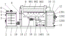
FIG. 1 is a schematic front sectional view of the present invention;
FIG. 2 is a schematic top view of the present invention;
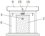
FIG. 3 is a left side view of the present invention;
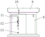
FIG. 4 is a schematic diagram of the right view structure of the present invention;
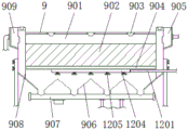
FIG. 5 is a schematic view of the front cross-sectional structure of the precipitation structure of the present invention;
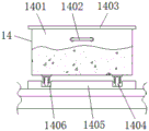
FIG. 6 is a schematic view of a front cross-sectional structure of a dirt collecting structure according to the present invention;
fig. 7 is a schematic bottom view of the spray plate of the present invention.
In the figure: 1. a support base plate; 2. a treatment tank; 3. a stirring shaft; 4. a medicine injection port; 5. a filter plate; 6. a water injection port; 7. a servo motor; 8. a support frame; 9. a precipitation structure; 901. a settling tank; 902. a sloping plate; 903. a water collection tank; 904. a spoiler; 905. a water outlet groove; 906. a settling hopper; 907. a sludge discharge pipe; 908. a rectifying plate; 909. a water inlet groove; 10. a water outlet pipe; 11. a water storage tank; 12. cleaning the structure; 1201. a first conduit; 1202. a water pump; 1203. a second conduit; 1204. a spray plate; 1205. a spray head; 13. a water outlet; 14. a dirt collecting structure; 1401. a sewage collection tank; 1402. a push-pull handle; 1403. a box opening; 1404. a pulley; 1405. a fixing plate; 1406. a chute; 15. a blow-off pipe; 16. a support block; 17. a sewage pump; 18. a delivery pipe; 19. a material pumping pump.
Detailed Description
The technical solutions in the embodiments of the present invention will be clearly and completely described below with reference to the drawings in the embodiments of the present invention, and it is obvious that the described embodiments are only a part of the embodiments of the present invention, and not all of the embodiments. All other embodiments, which can be derived by a person skilled in the art from the embodiments given herein without making any creative effort, shall fall within the protection scope of the present invention.
Referring to fig. 1-7, an embodiment of the present invention is shown: a tap water purifying sedimentation tank and a purifying method thereof comprise a supporting base plate 1, a processing box 2 is arranged on one side of the top end of the supporting base plate 1, a stirring shaft 3 is movably connected inside the processing box 2, a medicine injection port 4 is fixed on the top end of one side of the processing box 2, a filter plate 5 is arranged on the top end of the inside of the processing box 2, a water injection port 6 is fixed on one side of the top end of the processing box 2, a servo motor 7 is arranged on the top end of the processing box 2, the type of the servo motor 7 can be MR-J2S-10A, the input end of the servo motor 7 is electrically connected with the output end of a control panel through a lead, the output end of the servo motor 7 is fixedly connected with the stirring shaft 3 through a coupler, a supporting frame 8 is fixed on the top end of the supporting base plate 1, a sedimentation structure 9 is arranged on the top end of the supporting frame 8, a water, a water outlet pipe 10 is fixed at the top end of a water storage tank 11, a water outlet 13 is installed at the bottom end of one side of the water storage tank 11, a sewage collecting structure 14 is installed at one side of the bottom end of the interior of a support frame 8, a support block 16 is fixed at the bottom end of the interior of the support frame 8, a sewage pump 17 is installed at the top end of the support block 16, the type of the sewage pump 17 can be 100ZW15-30PB, the input end of the sewage pump 17 is electrically connected with the output end of a control panel through a lead, a sewage discharge pipe 15 is installed at one side of the sewage pump 17, a material pumping pump 19 is installed at the other side of a treatment box 2, the type of the material pumping pump 19 can be NYP, the input end of the material pumping pump 19 is electrically connected with the output end of the control panel through a lead;
the sedimentation structure 9 comprises a sedimentation tank 901, the sedimentation tank 901 is arranged at the top end inside a support frame 8, an inclined plate 902 is arranged inside the sedimentation tank 901, water collecting tanks 903 are arranged at the top ends inside the sedimentation tank 901, a water outlet tank 905 is fixed at the top end of one side of the sedimentation tank 901, one side of the water outlet tank 905 is fixedly connected with one side of a water outlet pipe 10, flow baffles 904 are fixed at the bottom ends of the inclined plates 902, sedimentation hoppers 906 are fixed at the bottom ends of the sedimentation tank 901, a mud discharge pipe 907 is fixed at the bottom end of the sedimentation hopper 906, a rectifying plate 908 is arranged at the other side inside the sedimentation tank 901, a water inlet tank 909 is fixed at the top end of the other side of the sedimentation tank 901, one side of the water inlet tank 909 is fixedly connected with one side of a conveying pipe 18, a plurality of water collecting tanks 903 are arranged at the top end inside the sedimentation tank 901, the plurality of water collecting tanks 903 are arranged at equal intervals, the water outlet grooves 905 and the water inlet grooves 909 are symmetrically distributed about the vertical center line of the settling tank 901, four settling hoppers 906 are arranged, the settling hoppers 906 are in a funnel-shaped design, and the settling hoppers 906 are arranged at equal intervals at the bottom end of the settling tank 901;
when the mechanism is used, firstly, after the water in the treatment tank 2 is filtered, the material pumping pump 19 is started through the control panel, the material pumping pump 19 injects the water in the treatment tank 2 into the water inlet groove 909 through the delivery pipe 18, the water inlet groove 909 conveys the water into the interior of the precipitation tank 901 for precipitation treatment, a plurality of dense inclined plates 902 are arranged in the region of the precipitation tank 901, the inclined plates 902 can precipitate suspended impurities in the water in the inclined plates 902, the water flows upwards along the inclined plates 902, the water collecting groove 903 can collect the ascending water at the moment, the separated impurities slide downwards along the inclined plates 902 to the bottom of the precipitation bucket 906 under the action of gravity and are discharged into the interior of the dirt collection tank 1401 through the mud discharge pipe 907, the clear water gradually rises to the water outlet groove 905 and is discharged into the interior of the water storage tank 11, the precipitation efficiency of the precipitation tank 901 can be improved through the inclined plates 902, the precipitation speed is higher, thereby improving the purification effect of the tap water;
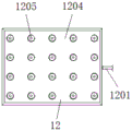
the cleaning structure 12 comprises a water pump 1202, the water pump 1202 is installed on one side of the water storage tank 11, the type of the water pump 1202 can be 500QZ, the input end of the water pump 1202 is electrically connected with the output end of the control panel through a conducting wire, a second conduit 1203 is fixed at the bottom end of the water pump 1202, one side of the second conduit 1203 is fixedly connected with one end of the water storage tank 11, a first conduit 1201 is fixed at the top end of the water pump 1202, a spray plate 1204 is fixed at one side of the first conduit 1201, the top end of the spray plate 1204 is fixedly connected with the bottom end of a spoiler 904, spray heads 1205 are fixed at the bottom end of the spray plate 1204, the second conduit 1203 is communicated with the water storage tank 11, the first conduit 1201 is communicated with the spray plate 1204, a plurality of spray heads 1205 are fixed at the bottom end of the spray plate 1204, and the plurality of spray;
when the mechanism is used, firstly, when the sedimentation bucket 906 at the bottom end of the sedimentation tank 901 is used for a long time, more impurities are accumulated in the sedimentation bucket 906, and the phenomenon of blockage can be caused, at the moment, the water pump 1202 is started through the control panel, the water pump 1202 can start up, the water pump 1202 can pump out the water in the water storage tank 11, the pumped water can be conveyed into the first conduit 1201 through the second conduit 1203, then the water is conveyed into the spraying plate 1204 through the first conduit 1201, due to the action of water pressure, the water can be sprayed out through the spray head 1205, the sprayed water is in a shower shape and can flush the interior of the sedimentation bucket 906, so that the sedimentation bucket 906 in the sedimentation tank 901 can be conveniently flushed, the phenomenon that the sludge discharge pipe 907 is blocked is prevented, and the cleanness of the sedimentation tank 901 during use is improved;
the sewage collecting structure 14 comprises a fixing plate 1405, the fixing plate 1405 is fixed at one side of the bottom end in the supporting frame 8, a sewage collecting tank 1401 is arranged at the top end of the fixing plate 1405, a push-pull handle 1402 is arranged at one end of the sewage collecting tank 1401, a tank opening 1403 is fixed at the top end of the sewage collecting tank 1401, pulleys 1404 are arranged on two sides of the bottom end of the sewage collecting tank 1401, sliding grooves 1406 are arranged on two sides of the top end in the fixing plate 1405, the outer diameter of each pulley 1404 is smaller than the inner diameter of each sliding groove 1406, and a sliding structure is formed between each pulley;
when the mechanism is used, firstly, impurities precipitated in the sediment tank 901 are discharged into the interior of the sewage collection tank 1401 through the sewage discharge pipe 15, when more precipitated impurities are stored in the sewage collection tank 1401, the push-pull handle 1402 is held and pulled forward, the push-pull handle 1402 drives the sewage collection tank 1401 to move, at the moment, the sewage collection tank 1401 enables the pulley 1404 to slide in the tank opening 1403, the push-pull handle 1402 is continuously pulled to enable the pulley 1404 to fall off from the interior of the sliding groove 1406, then the sewage collection tank is conveyed to a specified position, the precipitated impurities in the sewage collection tank 1401 are cleaned, the pulley 1404 is installed in the sliding groove 1406, the sewage collection tank 1401 is pushed to stop at the original position, and therefore the sewage collection tank 1401 is convenient to extract and clean, and convenience in use is improved.
The working principle is as follows: when the tap water purifying sedimentation tank and the purifying method thereof are used, the external power supply is connected, firstly, when the tap water needs to be purified, the tap water is injected into the processing box 2 from the water injection port 6, the filter plate 5 can primarily filter the tap water, a proper amount of medicine is injected into the processing box 2 through the medicine injection port 4, the medicine can react with the tap water, the servo motor 7 is started through the control panel, the output end of the servo motor 7 can drive the stirring shaft 3 to rotate, and the servo motor 7 can stir the water in the processing box 2 when rotating, so that the water and the medicine are fully mixed;
next, the pumping pump 19 is started through the control panel, the pumping pump 19 pumps the water inside the treatment tank 2 into the water inlet groove 909 through the delivery pipe 18, the water inlet groove 909 delivers the water into the interior of the precipitation tank 901 for precipitation treatment, a plurality of dense inclined plates 902 are arranged in the area of the settling tank 901, the inclined plates 902 can enable suspended impurities in water to settle in the inclined plates 902, the water flows upwards along the inclined plates 902, the water collecting tank 903 collects the upwards-flowing water, the separated impurities slide downwards to the bottom of the settling hopper 906 along the inclined plates 902 under the action of gravity, the sewage pump 17 is started through the control panel, impurities in the settling hopper 906 are conveyed to the inside of the sewage pipe 15 through the sludge pipe 907 by the sewage pump 17, finally the impurities are conveyed to the inside of the sewage collection tank 1401 through the sewage pipe 15, and the clean water gradually rises to the position of the water outlet groove 905 and is discharged into the water storage tank 11 through the water outlet pipe 10;
finally, when more precipitated impurities are stored in the sewage collection tank 1401, the push-pull handle 1402 is held and pulled forward, the push-pull handle 1402 drives the sewage collection tank 1401 to move, at the moment, the sewage collection tank 1401 can enable the pulley 1404 to slide in the tank opening 1403, the push-pull handle 1402 is continuously pulled to enable the pulley 1404 to fall off from the inside of the sliding groove 1406, then the sewage collection tank 1401 is conveyed to a specified position, the precipitated impurities in the sewage collection tank 1401 are cleaned, the pulley 1404 is installed in the sliding groove 1406, the push-pull handle 1402 is pushed to enable the sewage collection tank 1401 to stay at the original position, and finally the purification work of the tap water purification sedimentation tank and the purification method thereof is completed.
It will be evident to those skilled in the art that the invention is not limited to the details of the foregoing illustrative embodiments, and that the present invention may be embodied in other specific forms without departing from the spirit or essential attributes thereof. The present embodiments are therefore to be considered in all respects as illustrative and not restrictive, the scope of the invention being indicated by the appended claims rather than by the foregoing description, and all changes which come within the meaning and range of equivalency of the claims are therefore intended to be embraced therein. Any reference sign in a claim should not be construed as limiting the claim concerned.
Claims (10)
1. The utility model provides a running water purifies sedimentation tank, includes supporting baseplate (1), its characterized in that: a treatment box (2) is installed on one side of the top end of the supporting base plate (1), a stirring shaft (3) is movably connected inside the treatment box (2), a medicine injection port (4) is fixed on the top end of one side of the treatment box (2), a filter plate (5) is installed on the top end inside the treatment box (2), a water injection port (6) is fixed on one side of the top end of the treatment box (2), a servo motor (7) is installed on the top end of the treatment box (2), the output end of the servo motor (7) is fixedly connected with the stirring shaft (3) through a coupling, a support frame (8) is fixed on the top end of the supporting base plate (1), a precipitation structure (9) is installed on the top end inside the support frame (8), the precipitation structure (9) comprises a precipitation box (901), the precipitation box (901) is installed on the top end inside the support frame (8), and an inclined plate (902) is installed inside the, the top end of the interior of the settling tank (901) is provided with a water collecting tank (903), the top end of one side of the settling tank (901) is fixed with a water outlet tank (905), one side of the water outlet tank (905) is fixedly connected with one side of a water outlet pipe (10), the bottom end of the inclined plate (902) is fixed with a flow baffle (904), the bottom end of the settling tank (901) is fixed with a settling hopper (906), the bottom end of the settling hopper (906) is fixed with a mud discharge pipe (907), the other side of the interior of the settling tank (901) is provided with a rectifying plate (908), the top end of the other side of the settling tank (901) is fixed with a water inlet tank (909), one side of the water inlet tank (909) is fixedly connected with one side of a conveying pipe (18), the other side of the top end of the supporting base plate (1) is provided with a water storage tank (11), one side of the water storage tank (11) is provided with a, delivery port (13) are installed to the bottom of storage water tank (11) one side, dirty structure (14) of collection is installed to one side of the inside bottom of support frame (8), the inside bottom mounting of support frame (8) has supporting shoe (16), and the top of supporting shoe (16) installs dredge pump (17), blow off pipe (15) are installed to one side of dredge pump (17), pump (19) are installed to the opposite side of handling case (2), and the top fixed connection of the bottom of pump (19) and supporting baseplate (1), conveyer pipe (18) are installed to one side of pump (19).
2. The tap water purification sedimentation tank according to claim 1, wherein: the top end in the settling tank (901) is provided with a plurality of water collecting tanks (903), and the top ends of the water collecting tanks (903) in the settling tank (901) are arranged at equal intervals.
3. The tap water purification sedimentation tank according to claim 1, wherein: the areas of the water outlet groove (905) and the water inlet groove (909) are equal, and the water outlet groove (905) and the water inlet groove (909) are symmetrically distributed around the vertical center line of the settling tank (901).
4. The tap water purification sedimentation tank according to claim 1, wherein: the sedimentation bucket (906) all are provided with four, sedimentation bucket (906) all are the infundibulate design, sedimentation bucket (906) are the equidistant range in the bottom of setting tank (901).
5. The tap water purification sedimentation tank according to claim 1, wherein: wash structure (12) and include water pump (1202), install in one side of storage water tank (11) water pump (1202), the bottom mounting of water pump (1202) has second pipe (1203), and one side of second pipe (1203) and the one end fixed connection of storage water tank (11), the top of water pump (1202) is fixed with first pipe (1201), and one side of first pipe (1201) is fixed with sprays board (1204), the top of spraying board (1204) and the bottom fixed connection of spoiler (904), the bottom of spraying board (1204) all is fixed with shower nozzle (1205).
6. The tap water purification sedimentation tank according to claim 5, wherein: the second conduit (1203) is communicated with the water storage tank (11), and the first conduit (1201) is communicated with the spraying plate (1204).
7. The tap water purification sedimentation tank according to claim 5, wherein: the bottom of spraying plate (1204) is fixed with a plurality of shower nozzle (1205), a plurality of shower nozzle (1205) is evenly distributed at the bottom of spraying plate (1204).
8. The tap water purification sedimentation tank according to claim 1, wherein: dirty structure (14) of collection include fixed plate (1405), fixed plate (1405) are fixed in one side of the inside bottom of support frame (8), the top of fixed plate (1405) is provided with collection dirty case (1401), and the one end of collection dirty case (1401) is provided with push-and-pull handle (1402), the top of collection dirty case (1401) is fixed with case mouth (1403), pulley (1404) are all installed to the both sides of collection dirty case (1401) bottom, the both sides on the inside top of fixed plate (1405) all are provided with spout (1406).
9. The tap water purification sedimentation tank according to claim 8, wherein: the outer diameter of the pulley (1404) is smaller than the inner diameter of the sliding groove (1406), and a sliding structure is formed between the pulley (1404) and the sliding groove (1406).
10. A purification method of a tap water purification sedimentation tank is characterized by comprising the following steps:
s1, filtering and adding medicine
Running water is injected into the treatment box 2 from the water injection port 6, the filter plate 5 can carry out primary filtration on the running water, a proper amount of medicine is injected into the treatment box 2 through the medicine injection port 4, the medicine can react with the running water, the servo motor 7 is started through the control panel, the output end of the servo motor 7 can drive the stirring shaft 3 to rotate, and the servo motor 7 can stir the water in the treatment box 2 when rotating, so that the water and the medicine are fully mixed;
s2 inclined plate sedimentation
The pumping pump 19 is started through the control panel, the pumping pump 19 injects the water inside the treatment tank 2 into the water inlet groove 909 through the delivery pipe 18, and the water inlet groove 909 delivers the water into the interior of the precipitation tank 901 for precipitation treatment, which is specifically as follows;
s201, arranging a plurality of dense inclined plates 902 in the area of a settling tank 901, wherein the inclined plates 902 can enable suspended impurities in water to settle in the inclined plates 902, the water flows upwards along the inclined plates 902, the water collecting tank 903 collects the upwards-flowing water, and the separated impurities slide downwards to the bottom of a settling hopper 906 along the inclined plates 902 under the action of gravity;
s202, the sewage pump 17 is started through the control panel, impurities in the settling hopper 906 can be conveyed to the interior of the sewage pipe 15 through the sludge pipe 907 by the sewage pump 17, finally the impurities are conveyed to the interior of the sewage collection box 1401 through the sewage pipe 15, and clean water gradually rises to the position of the water outlet groove 905 and is discharged into the water storage tank 11 through the water outlet pipe 10;
s3, dirt collecting treatment
When more precipitated impurities are stored in the sewage collection tank 1401, the push-pull handle 1402 is held and pulled forward, the push-pull handle 1402 drives the sewage collection tank 1401 to move, at the moment, the sewage collection tank 1401 can enable the pulley 1404 to slide in the tank opening 1403, the push-pull handle 1402 is continuously pulled to enable the pulley 1404 to fall off from the inside of the sliding groove 1406, then the sewage collection tank 1401 is conveyed to a specified position, the precipitated impurities in the sewage collection tank 1401 are cleaned, the pulley 1404 is installed in the sliding groove 1406, the push-pull handle 1402 is pushed to enable the sewage collection tank 1401 to stay at the original position, and finally the purification work of the tap water purification sedimentation tank and the purification method thereof is completed.
Priority Applications (1)
| Application Number | Priority Date | Filing Date | Title |
|---|---|---|---|
| CN202011076302.9A CN112125446A (en) | 2020-10-10 | 2020-10-10 | Tap water purification sedimentation tank and purification method thereof |
Applications Claiming Priority (1)
| Application Number | Priority Date | Filing Date | Title |
|---|---|---|---|
| CN202011076302.9A CN112125446A (en) | 2020-10-10 | 2020-10-10 | Tap water purification sedimentation tank and purification method thereof |
Publications (1)
| Publication Number | Publication Date |
|---|---|
| CN112125446A true CN112125446A (en) | 2020-12-25 |
Family
ID=73844143
Family Applications (1)
| Application Number | Title | Priority Date | Filing Date |
|---|---|---|---|
| CN202011076302.9A Pending CN112125446A (en) | 2020-10-10 | 2020-10-10 | Tap water purification sedimentation tank and purification method thereof |
Country Status (1)
| Country | Link |
|---|---|
| CN (1) | CN112125446A (en) |
Cited By (2)
| Publication number | Priority date | Publication date | Assignee | Title |
|---|---|---|---|---|
| CN114788970A (en) * | 2022-03-07 | 2022-07-26 | 江苏瑞赛克环保设备科技股份有限公司 | Waste tire cleaning water cyclic utilization device |
| CN116397729A (en) * | 2023-06-07 | 2023-07-07 | 四川发展环境科学技术研究院有限公司 | Small and medium-sized high-efficiency water supply treatment method |
-
2020
- 2020-10-10 CN CN202011076302.9A patent/CN112125446A/en active Pending
Cited By (3)
| Publication number | Priority date | Publication date | Assignee | Title |
|---|---|---|---|---|
| CN114788970A (en) * | 2022-03-07 | 2022-07-26 | 江苏瑞赛克环保设备科技股份有限公司 | Waste tire cleaning water cyclic utilization device |
| CN116397729A (en) * | 2023-06-07 | 2023-07-07 | 四川发展环境科学技术研究院有限公司 | Small and medium-sized high-efficiency water supply treatment method |
| CN116397729B (en) * | 2023-06-07 | 2023-08-29 | 四川发展环境科学技术研究院有限公司 | Small and medium-sized high-efficiency water supply treatment method |
Similar Documents
| Publication | Publication Date | Title |
|---|---|---|
| CN112125446A (en) | Tap water purification sedimentation tank and purification method thereof | |
| CN112245979B (en) | High-efficient sedimentation tank convenient to clearance | |
| CN206955795U (en) | Dirty tank car is taken out in a kind of sewage purification separation | |
| CN215855440U (en) | Air supporting machine with deposit function | |
| CN110721499A (en) | Reverse flow inclined tube sedimentation tank | |
| CN209161574U (en) | A kind of flocculation sedimentation tank | |
| CN110917668A (en) | Precipitation device for sewage treatment | |
| CN111359966B (en) | Continuous flushing machine for waste plastic fragments | |
| CN106698713B (en) | Solid-liquid separation system in sewage treatment | |
| CN205999025U (en) | Micropowder washing and impurity removing equipment | |
| CN206604232U (en) | A kind of sewage-treatment plant and its tube settler | |
| CN213192859U (en) | Direct drinking water supply system | |
| CN208320067U (en) | A kind of up-flow inclined-tube sedimentation tank with anti-cleaning function | |
| CN216273431U (en) | Power station grit aggregate waste water treatment equipment | |
| CN214032040U (en) | Container type treatment device for sewage in construction site | |
| CN215505631U (en) | High-efficient environmental protection sedimentation tank for sewage treatment | |
| CN219502074U (en) | Purifying tank for town sewage treatment | |
| CN219023372U (en) | Sedimentation tank for ocean sewage treatment process | |
| CN215692377U (en) | Automatic cleaning device of marsh gas raw material pond deposit silt | |
| CN216191314U (en) | Improved generation sewage treatment's precipitation equipment | |
| CN215841773U (en) | Sewage settling tank with sludge treatment capacity | |
| CN219662960U (en) | Device for extracting sludge from wastewater | |
| CN217340199U (en) | Novel radial flow sedimentation tank | |
| CN220589038U (en) | Inclined tube sedimentation tank inclined tube top mud accumulation cleaning device | |
| CN215712181U (en) | A sewage treatment system for loading in mixture emulsion explosive production link |
Legal Events
| Date | Code | Title | Description |
|---|---|---|---|
| PB01 | Publication | ||
| PB01 | Publication | ||
| SE01 | Entry into force of request for substantive examination | ||
| SE01 | Entry into force of request for substantive examination | ||
| WD01 | Invention patent application deemed withdrawn after publication | ||
| WD01 | Invention patent application deemed withdrawn after publication |
Application publication date: 20201225 |