CN112109203A - Self-cleaning building slurry stirring equipment in field of building machinery - Google Patents
Self-cleaning building slurry stirring equipment in field of building machinery Download PDFInfo
- Publication number
- CN112109203A CN112109203A CN202011024955.2A CN202011024955A CN112109203A CN 112109203 A CN112109203 A CN 112109203A CN 202011024955 A CN202011024955 A CN 202011024955A CN 112109203 A CN112109203 A CN 112109203A
- Authority
- CN
- China
- Prior art keywords
- stirring
- support frame
- self
- cleaning
- locking
- Prior art date
- Legal status (The legal status is an assumption and is not a legal conclusion. Google has not performed a legal analysis and makes no representation as to the accuracy of the status listed.)
- Pending
Links
Images


Classifications
-
- B—PERFORMING OPERATIONS; TRANSPORTING
- B28—WORKING CEMENT, CLAY, OR STONE
- B28C—PREPARING CLAY; PRODUCING MIXTURES CONTAINING CLAY OR CEMENTITIOUS MATERIAL, e.g. PLASTER
- B28C5/00—Apparatus or methods for producing mixtures of cement with other substances, e.g. slurries, mortars, porous or fibrous compositions
- B28C5/08—Apparatus or methods for producing mixtures of cement with other substances, e.g. slurries, mortars, porous or fibrous compositions using driven mechanical means affecting the mixing
- B28C5/10—Mixing in containers not actuated to effect the mixing
- B28C5/12—Mixing in containers not actuated to effect the mixing with stirrers sweeping through the materials, e.g. with incorporated feeding or discharging means or with oscillating stirrers
- B28C5/14—Mixing in containers not actuated to effect the mixing with stirrers sweeping through the materials, e.g. with incorporated feeding or discharging means or with oscillating stirrers the stirrers having motion about a horizontal or substantially horizontal axis
- B28C5/141—Mixing in containers not actuated to effect the mixing with stirrers sweeping through the materials, e.g. with incorporated feeding or discharging means or with oscillating stirrers the stirrers having motion about a horizontal or substantially horizontal axis with container tiltable or elevatable for emptying
-
- B—PERFORMING OPERATIONS; TRANSPORTING
- B08—CLEANING
- B08B—CLEANING IN GENERAL; PREVENTION OF FOULING IN GENERAL
- B08B9/00—Cleaning hollow articles by methods or apparatus specially adapted thereto
- B08B9/08—Cleaning containers, e.g. tanks
- B08B9/087—Cleaning containers, e.g. tanks by methods involving the use of tools, e.g. brushes, scrapers
-
- B—PERFORMING OPERATIONS; TRANSPORTING
- B28—WORKING CEMENT, CLAY, OR STONE
- B28C—PREPARING CLAY; PRODUCING MIXTURES CONTAINING CLAY OR CEMENTITIOUS MATERIAL, e.g. PLASTER
- B28C5/00—Apparatus or methods for producing mixtures of cement with other substances, e.g. slurries, mortars, porous or fibrous compositions
- B28C5/08—Apparatus or methods for producing mixtures of cement with other substances, e.g. slurries, mortars, porous or fibrous compositions using driven mechanical means affecting the mixing
- B28C5/0806—Details; Accessories
- B28C5/0812—Drum mixer cover, e.g. lid
-
- B—PERFORMING OPERATIONS; TRANSPORTING
- B28—WORKING CEMENT, CLAY, OR STONE
- B28C—PREPARING CLAY; PRODUCING MIXTURES CONTAINING CLAY OR CEMENTITIOUS MATERIAL, e.g. PLASTER
- B28C5/00—Apparatus or methods for producing mixtures of cement with other substances, e.g. slurries, mortars, porous or fibrous compositions
- B28C5/08—Apparatus or methods for producing mixtures of cement with other substances, e.g. slurries, mortars, porous or fibrous compositions using driven mechanical means affecting the mixing
- B28C5/0806—Details; Accessories
- B28C5/0818—Charging or discharging gates or chutes; Sealing means
-
- B—PERFORMING OPERATIONS; TRANSPORTING
- B28—WORKING CEMENT, CLAY, OR STONE
- B28C—PREPARING CLAY; PRODUCING MIXTURES CONTAINING CLAY OR CEMENTITIOUS MATERIAL, e.g. PLASTER
- B28C5/00—Apparatus or methods for producing mixtures of cement with other substances, e.g. slurries, mortars, porous or fibrous compositions
- B28C5/08—Apparatus or methods for producing mixtures of cement with other substances, e.g. slurries, mortars, porous or fibrous compositions using driven mechanical means affecting the mixing
- B28C5/0806—Details; Accessories
- B28C5/0831—Drives or drive systems, e.g. toothed racks, winches
-
- B—PERFORMING OPERATIONS; TRANSPORTING
- B28—WORKING CEMENT, CLAY, OR STONE
- B28C—PREPARING CLAY; PRODUCING MIXTURES CONTAINING CLAY OR CEMENTITIOUS MATERIAL, e.g. PLASTER
- B28C5/00—Apparatus or methods for producing mixtures of cement with other substances, e.g. slurries, mortars, porous or fibrous compositions
- B28C5/08—Apparatus or methods for producing mixtures of cement with other substances, e.g. slurries, mortars, porous or fibrous compositions using driven mechanical means affecting the mixing
- B28C5/0806—Details; Accessories
- B28C5/0856—Supporting frames or structures, e.g. supporting wheels
-
- B—PERFORMING OPERATIONS; TRANSPORTING
- B28—WORKING CEMENT, CLAY, OR STONE
- B28C—PREPARING CLAY; PRODUCING MIXTURES CONTAINING CLAY OR CEMENTITIOUS MATERIAL, e.g. PLASTER
- B28C7/00—Controlling the operation of apparatus for producing mixtures of clay or cement with other substances; Supplying or proportioning the ingredients for mixing clay or cement with other substances; Discharging the mixture
- B28C7/16—Discharge means, e.g. with intermediate storage of fresh concrete
Abstract
The invention discloses self-cleaning building slurry stirring equipment in the field of building machinery, relates to the technical field of stirrers, and solves the problems of easy accumulation of raw materials, poor stirring effect and incomplete cleaning of the existing building stirrer; one side of the top of the lower support frame is fixedly and symmetrically connected with two connecting support columns in total through welding in a front-back mode; a locking rod is embedded into the inner sides of the locking support blocks in a sliding manner; the inboard equal fixed symmetrical connection of locking supporting shoe has two guide bars, and the guide bar passes two round holes in the push pedal, because the raw materials in four charge inlets can be even fall to the internal different positions of agitator tank, can not make the raw materials pile up together because the agitator tank is vertical, therefore the thick liquids after the stirring are more even, and stirring effect can improve greatly, compares and only washes with the water moreover, and the cleaning round bar can get rid of inside adnexed most thick liquids, and cleaning performance improves greatly.
Description
Technical Field
The invention relates to the technical field of mixers, in particular to self-cleaning building slurry mixing equipment in the field of building machinery.
Background
The concrete is a general term for engineering composite materials formed by cementing aggregate into a whole by cementing materials, the term concrete generally refers to cement concrete which is obtained by mixing cement as the cementing material, sand and stone as the aggregate and water (which may contain additives and admixtures) according to a certain proportion and stirring, and is also called ordinary concrete.
For example, the patent with the application number of 201920745013.X discloses a self-cleaning concrete mixer, which comprises two supporting legs and two supporting legs, wherein the two supporting legs are fixedly connected with the same stirring box, the top of the stirring box is clamped with a box cover, the bottom of the stirring box and the lower surface of the box cover are fixedly connected with the same annular filter plate, the middle position of the upper surface of the box cover is fixedly provided with a first motor, the output end of the first motor penetrates through the box cover and is fixedly connected with a stirring rod, the utility model can ensure that a spray head in a cleaning mechanism sprays water for cleaning at different heights and different angles in the stirring box through the matched use of a first connecting mechanism, a second connecting mechanism, a cleaning mechanism, an annular chute and an annular track, thereby ensuring that the cleaning is more complete and thorough, solving the problems of cleaning dead angle and low cleaning efficiency in the prior art, and simultaneously realizing the automatic cleaning treatment, the problem of need artifical the holding among the traditional art is solved, and clean fast.
Based on the above, most of existing building mixers are vertical mixers, and the raw materials are deposited at the bottom of the building mixers, so that the mixed slurry may not be uniform and have poor mixing effect, and if the discharge port is formed at the outer side, the slurry may not completely flow out, some mixers are provided with self-cleaning devices, and most of the mixers are directly washed by water, but some stubborn slurry attached to the inner part is difficult to wash down and cannot completely clean; therefore, the existing requirements are not met, and a self-cleaning construction slurry stirring device in the field of construction machinery is provided for the requirement.
Disclosure of Invention
The invention aims to provide self-cleaning building slurry stirring equipment in the field of building machinery, and aims to solve the problems that most of existing building stirrers in the background art are vertical stirrers, raw materials are put in the vertical stirrers and then are deposited at the bottom, so that the stirred slurry is possibly uneven and has poor stirring effect, if a discharge hole is formed in the outer side, the slurry can not flow out completely, some stirrers are provided with self-cleaning devices and are mostly washed by water directly, but some stubborn slurry attached to the inner part is difficult to wash down, and the washing is not complete.
In order to achieve the purpose, the invention provides the following technical scheme: a self-cleaning construction slurry stirring device in the field of construction machinery comprises a lower support frame and a cleaning round rod; one side of the top of the lower support frame is fixedly and symmetrically connected with two connecting support columns in total through welding in a front-back mode; a rotatable connecting round rod is fixedly embedded between the tops of the two connecting support columns; the top of the connecting round rod is fixedly connected with one side of the bottom of the upper support frame; the top of the lower support frame is also fixedly and symmetrically connected with four support legs in total through welding; the other side of the lower support frame is fixedly connected with two multi-section hydraulic telescopic rods which are symmetrical front and back through a rotating shaft, and the tops of the two multi-section hydraulic telescopic rods are respectively and fixedly connected with the other side of the bottom of the upper support frame through the rotating shaft; the top of the upper support frame is fixedly provided with a stirring box body through a bolt; the top of the stirring box body is fixedly provided with four feeding ports at equal intervals; a group of feeding baffle plates are fixedly arranged on the inner sides of the four feeding ports through welding; a rotatable stirring shaft is fixedly arranged on the inner side of the stirring box body; a group of stirring teeth is fixedly arranged on the outer side of the stirring shaft; the cleaning round rod is fixedly embedded and arranged at the outer side of the stirring teeth; the other side of the top of the upper support frame is also fixedly provided with a motor fixing frame through a bolt; the top of the motor fixing frame is fixedly provided with a servo motor; a rotating shaft of the servo motor is fixedly connected with one end of the stirring shaft; a discharging cover is fixedly embedded at the bottom of one side of the stirring box body; one side of the stirring box body is also fixedly provided with two locking supporting blocks which are symmetrical front and back; a locking rod is embedded into the inner sides of the locking support blocks in a sliding manner; the outer sides of the locking rods are fixedly connected with a push plate; the inner side of the locking supporting block is also fixedly and symmetrically connected with two guide rods, and the guide rods penetrate through two round holes in the push plate.
Preferably, the lower support frame is connected with the upper support frame through the connection support column and the connection round rod rotation, and the upper support frame can rotate around the connection support column top through the connection round rod, and then can drive the agitator tank body at top rotatory to the tilt state.
Preferably, when the multiple sections of hydraulic telescopic rods extend, the right side of the upper support frame can be pushed to move leftwards and upwards in an arc-shaped track, and rotating shafts are arranged at the top and the bottom of the multiple sections of hydraulic telescopic rods, so that the angles of the multiple sections of hydraulic telescopic rods can rotate, and the right side of the upper support frame is rotated upwards to enable the upper support frame to incline integrally.
Preferably, the supporting leg top is Y shape structure, and the top intermediate position is provided with the draw-in groove that equals with upper bracket side frame width together, and the side frame of its front and back side can imbed in the draw-in groove at four supporting leg tops when upper bracket downwardly rotating to the level.
Preferably, the locking supporting block is C font structure, and the bellied intermediate position in both sides all is provided with a quad slit, and the check lock lever just alternates in these two quad slits, and the push pedal is located between these two archs, and the guide bar also is located between these two archs, and the guide bar outside all is fixed and is provided with a spring moreover, and the spring can promote push pedal and check lock lever all the time and slide to one side at ejection of compact lid place.
Preferably, the bottommost of the mounting hole of ejection of compact lid is located same horizontal plane with agitator tank inner chamber bottommost, and the fixed symmetry in ejection of compact lid outside is provided with two sets of lugs, and the interval of lug equals with the width of check lock, and the check lock can closely laminate with the ejection of compact lid outside after sliding to the ejection of compact lid outside, and the check lock can imbed between the lug in the ejection of compact lid outside moreover.
Preferably, the feeding baffle plate above the inner side of the feeding port is high in left side and low in right side, and is provided with a right side opening, and the feeding baffle plate below is high in right side and low in left side, and is provided with a left side opening.
Preferably, clean round bar is cylindrical pole, and the surface is dull polish form, and the fixed semicircular hole that is provided with a set of horizontal in stirring tooth bottom, and the hole diameter equals with clean round bar diameter, and back in the semicircular hole of this group's stirring tooth bottom is installed in the embedding of clean round bar, the clean round bar outside can contact with agitator tank inner chamber, and the fixed vertical cylindricality arch that is provided with one in (mixing) shaft right side top moreover, and the bellied direction of cylindricality is opposite from top to bottom with the direction of semicircular hole.
Compared with the prior art, the invention has the beneficial effects that:
first, when using this device to the thick liquids stirring, earlier rotatory to the horizontality with the upper bracket frame of this device, and install ejection of compact lid, then open servo motor and drive the (mixing) shaft and the continuous rotation of stirring tooth, at this moment can pour into the raw materials and the water that need the stirring from four charge inlets, equal amount raw materials and water are all poured into to every charge inlet, these raw materials and water can fall into the reinforced baffle top of the below of the slip of the reinforced baffle top of top and right side below earlier, the slip of below left side can fall into the stirring box inside and stir, because the raw materials in four charge inlets can be even fall into different positions in the stirring box, can not make the raw materials pile up together because the stirring box is vertical, therefore the thick liquids after the stirring are more even, stirring effect can improve greatly.
Second, when thick liquids stir and need outwards take out after accomplishing, promote multisection hydraulic telescoping rod extension through outside hydraulic oil pump, thereby promote support frame right side upward movement around connecting the support column top rotation to the low right side high state in left side, then open ejection of compact lid, will stimulate respectively to both sides two check lock levers when opening, then outwards pull out ejection of compact lid can, at this moment servo motor continues to drive the (mixing) shaft and the rotation of stirring tooth, inside thick liquids can outwards flow through the discharge gate of agitator tank left side below behind the agitator tank slope, and thick liquids outflow efficiency is higher after whole slope, it is also more thorough to flow, it is very convenient during the thick liquids of discharging.
Third, when needs are to the inside washing of agitator tank, the semicircular hole that drives the stirring tooth outside through servo motor earlier rotates bottommost, through with the cylindricality protruding rotation to the top on (mixing) shaft right side can, need not to observe inside during the rotation and can accomplish, then in the discharge gate that will clean the round bar from agitator tank left side below inwards inserts the semicircular hole in the stirring tooth outside, then install ejection of compact lid, it is rotatory to open servo motor drive (mixing) shaft after adding water through the charge door, at this moment, the stirring tooth can drive clean round bar and constantly rub in agitator tank inner chamber, wash than only water, clean round bar can get rid of inside adnexed most thick liquids, the cleaning performance improves greatly.
Drawings
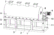
FIG. 1 is a schematic diagram of the right side of the shaft for normal stirring according to the present invention;
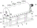
FIG. 2 is a schematic view of the left side of the present invention during normal stirring;
FIG. 3 is a schematic diagram of the right side of the stirring box according to the present invention after rotation;
FIG. 4 is a schematic view of the left side of the agitator tank of the present invention after rotation;
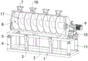
FIG. 5 is a schematic view of the right side of the present invention with a partial cut;
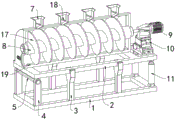
FIG. 6 is a schematic view of the left side of the cleaning rod of the present invention with a partial cut-away view;
FIG. 7 is an enlarged partial view of FIG. 2 at point A;
FIG. 8 is an enlarged partial view of the structure of FIG. 4 at point B;
FIG. 9 is an enlarged partial view of the structure of FIG. 5 at point C;
in the figure: 1. a lower support frame; 2. an upper support frame; 3. supporting legs; 4. connecting the supporting columns; 5. connecting the round rod; 6. a stirring box body; 7. a feed inlet; 8. a stirring shaft; 9. a servo motor; 10. a motor fixing frame; 11. a multi-section hydraulic telescopic rod; 12. a discharging cover; 13. locking the supporting block; 14. a locking lever; 15. a guide bar; 16. pushing the plate; 17. stirring teeth; 18. a feeding baffle plate; 19. cleaning the round bar.
Detailed Description
The technical solutions in the embodiments of the present invention will be clearly and completely described below with reference to the drawings in the embodiments of the present invention, and it is obvious that the described embodiments are only a part of the embodiments of the present invention, and not all of the embodiments.
Referring to fig. 1 to 9, an embodiment of the present invention includes: a self-cleaning construction slurry stirring device in the field of construction machinery comprises a lower support frame 1 and a cleaning round rod 19; one side of the top of the lower support frame 1 is fixedly and symmetrically connected with two connecting support columns 4 in total through welding; a rotatable connecting round rod 5 is fixedly embedded between the tops of the two connecting support columns 4; the top of the connecting round rod 5 is fixedly connected with one side of the bottom of the upper support frame 2; the top of the lower support frame 1 is also fixedly and symmetrically connected with four support legs 3 in total through welding; the tops of the supporting legs 3 are Y-shaped structures, a clamping groove with the width equal to that of the side frame of the upper supporting frame 2 is formed in the middle of the top, the side frames on the front side and the rear side of the upper supporting frame 2 can be embedded into the clamping grooves in the tops of the four supporting legs 3 when the upper supporting frame 2 rotates downwards to be horizontal, the supporting legs 3 can also support the upper supporting frame 2 when the upper supporting frame is placed in a horizontal state, and the stability is further improved; the other side of the lower support frame 1 is fixedly connected with two multi-section hydraulic telescopic rods 11 which are symmetrical front and back through a rotating shaft, and the tops of the two multi-section hydraulic telescopic rods 11 are respectively and fixedly connected with the other side of the bottom of the upper support frame 2 through the rotating shaft; when the multiple sections of hydraulic telescopic rods 11 extend, the right side of the upper support frame 2 can be pushed to move leftwards and upwards in an arc-shaped track, and because rotating shafts are arranged at the top and the bottom of the multiple sections of hydraulic telescopic rods 11, the angles of the multiple sections of hydraulic telescopic rods 11 can rotate, so that the right side of the upper support frame 2 is rotated upwards to enable the upper support frame 2 to integrally incline, when slurry needs to be taken out outwards after stirring is completed, the multiple sections of hydraulic telescopic rods 11 are pushed to extend through an external hydraulic oil pump, so that the right side of the upper support frame 2 is pushed to move upwards to rotate around the top of the connecting support column 4 to a high state with a low left side and a low right side, then the discharging cover 12 is opened, at the moment, the servo motor 9 continues to drive the stirring shaft 8 and the stirring teeth 17 to rotate, the slurry inside, the slurry is very convenient to discharge; the top of the upper supporting frame 2 is fixedly provided with a stirring box body 6 through a bolt; the top of the stirring box body 6 is fixedly provided with four feeding ports 7 at equal intervals; a group of feeding baffles 18 are fixedly arranged on the inner sides of the four feeding ports 7 through welding; a rotatable stirring shaft 8 is fixedly arranged on the inner side of the stirring box body 6; a group of stirring teeth 17 is fixedly arranged on the outer side of the stirring shaft 8; the cleaning round rod 19 is fixedly embedded and arranged at the outer side of the stirring teeth 17; the other side of the top of the upper support frame 2 is also fixedly provided with a motor fixing frame 10 through bolts; a servo motor 9 is fixedly arranged at the top of the motor fixing frame 10; a rotating shaft of the servo motor 9 is fixedly connected with one end of the stirring shaft 8; a discharging cover 12 is fixedly embedded at the bottom of one side of the stirring box body 6; the bottommost part of the mounting hole of the discharging cover 12 and the bottommost part of the inner cavity of the stirring box body 6 are located on the same horizontal plane, two groups of convex blocks are fixedly and symmetrically arranged on the outer side of the discharging cover 12, the distance between the convex blocks is equal to the width of the locking rod 14, the locking rod 14 can be tightly attached to the outer side of the discharging cover 12 after sliding towards the outer side of the discharging cover 12, the locking rod 14 can be embedded between the convex blocks on the outer side of the discharging cover 12, the two locking rods 14 are pulled towards two sides respectively when the discharging cover 12 is mounted, then the discharging cover 12 is embedded into the discharging hole, the convex blocks on the outer side of the discharging cover 12 are horizontal, the locking rod 14 is loosened, the locking rod 14 can slide between the convex blocks on the outer side of the discharging cover 12 due to the pushing of a spring; two locking support blocks 13 which are symmetrical front and back are fixedly arranged on one side of the stirring box body 6; a locking rod 14 is embedded into the inner sides of the locking support blocks 13 in a sliding manner; the outer sides of the locking rods 14 are fixedly connected with a push plate 16; the inner sides of the locking support blocks 13 are also fixedly and symmetrically connected with two guide rods 15, and the guide rods 15 penetrate through two round holes in the push plate 16.
Further, the lower support frame 1 is rotatably connected with the upper support frame 2 through a connecting support column 4 and a connecting round rod 5, the upper support frame 2 can rotate around the top of the connecting support column 4 through the connecting round rod 5, and then the stirring box body 6 at the top can be driven to rotate to an inclined state, when the slurry is required to be taken out after being stirred, the multi-section hydraulic telescopic rod 11 is pushed to extend through the external hydraulic oil pump, thereby pushing the right side of the upper support frame 2 to move upwards and rotate around the top of the connecting support column 4 to a high state with a low left side and a high right side, then the discharging cover 12 is opened, at this time, the servo motor 9 continues to drive the stirring shaft 8 and the stirring teeth 17 to rotate, the slurry inside the stirring box body 6 after being inclined flows out through the discharging hole at the lower part of the left side of the stirring box body 6, and the slurry flows out more efficiently and more thoroughly after the whole body is inclined, and the slurry is very convenient to discharge.
Further, locking supporting shoe 13 is C font structure, and the bellied intermediate position in both sides all is provided with a quad slit, check lock 14 just alternates in these two quad slits, and push pedal 16 is located between these two archs, guide bar 15 also is located between these two archs, and the equal fixed spring that is provided with in guide bar 15 outside, the spring can promote push pedal 16 and check lock 14 all the time and slide to one side at ejection of compact lid 12 place, will go out when material lid 12 is installed will two check lock 14 respectively to both sides pulling, then will go out material lid 12 embedding discharge opening in and make the lug level in the ejection of compact lid 12 outside, at this moment loosen check lock 14, check lock 14 can slide to between the lug in the ejection of compact lid 12 outside because of the spring promotes, thereby it is fixed to go out material lid 12, it is very convenient when fixed.
Further, the reinforced plate washer 18 of charge door 7 inboard top left side height right side is low, and the right side opening, the reinforced plate washer 18 right side height left side of below is low, and the left side opening, can drop the reinforced plate washer 18 top of top earlier and the reinforced plate washer 18 top of below that slides to the right side below when adding raw materials and water, slide to the left side below again and can drop 6 inside stirs of agitator tank, reinforced plate washer 18 can also play the effect of sheltering from when stirring thick liquids, thick liquids outwards splash from charge door 7 when preventing to stir.
Further, the cleaning round rod 19 is a cylindrical rod, the outer surface of the cleaning round rod is frosted, a group of transverse semicircular holes are fixedly arranged at the bottom of the stirring teeth 17, the hole diameter is equal to the diameter of the cleaning round rod 19, after the cleaning round rod 19 is embedded in the semicircular holes at the bottom of the group of stirring teeth 17, the outer side of the cleaning round rod 19 can be contacted with the inner cavity of the stirring box body 6, a vertical cylindrical bulge is fixedly arranged at the top of the right side of the stirring shaft 8, the direction of the cylindrical bulge is opposite to the direction of the semicircular holes, when the inner part of the stirring box body 6 needs to be cleaned, the semicircular holes at the outer side of the stirring teeth 17 are driven by the servo motor 9 to rotate to the bottommost part, the cylindrical bulge at the right side of the stirring shaft 8 is rotated to the top part, the inner part does not need to be observed during the rotation, then the cleaning round rod 19 is inwards inserted into, then with the installation of ejection of compact lid 12, open servo motor 9 and drive the (mixing) shaft 8 rotation after adding water through charge door 7, at this moment stirring tooth 17 can drive clean round bar 19 constantly rubs in 6 inner chambers of agitator tank, washes than only the water, and clean round bar 19 can get rid of inside adnexed most thick liquids, and the cleaning performance improves greatly, and it can outwards take out to rotate to the below with clean round bar 19 after wasing again.
The working principle is as follows: when the device is used for stirring slurry, the upper support frame 2 of the device is firstly rotated to be in a horizontal state, the support legs 3 can also support the upper support frame 2 when the upper support frame 2 is placed in the horizontal state, the stability is further improved, the discharging cover 12 is installed, two locking rods 14 are firstly pulled towards two sides respectively during installation, then the discharging cover 12 is embedded into the discharging hole, the convex blocks on the outer side of the discharging cover 12 are made to be horizontal, at the moment, the locking rods 14 are loosened, the locking rods 14 can slide to the positions between the convex blocks on the outer side of the discharging cover 12 due to the pushing of springs, so that the discharging cover 12 is fixed, then the servo motor 9 is started to drive the stirring shaft 8 and the stirring teeth 17 to rotate continuously, at the moment, raw materials and water to be stirred can be poured into the four feeding ports 7, equal amount of raw materials and water are poured into each feeding port 7, the raw materials and the water can fall onto the top of the feeding baffle plate 18 on the upper side and slide to the, the slurry can fall into the stirring box body 6 to be stirred by sliding towards the left lower part, because the raw materials in the four charging openings 7 can uniformly fall into different positions in the stirring box body 6, the raw materials can not be stacked together because the stirring box body 6 is vertical, the stirred slurry is more uniform, the stirring effect can be greatly improved, the feeding baffle plate 18 can play a role of shielding when the slurry is stirred, the slurry is prevented from splashing outwards from the charging openings 7 when being stirred, when the slurry is required to be taken out after being stirred, the multi-section hydraulic telescopic rod 11 is pushed by the external hydraulic oil pump to extend, so that the right side of the upper support frame 2 is pushed to move upwards to rotate around the top of the connecting support column 4 to a left side low-right side high state, then the discharging cover 12 is opened, the two locking rods 14 are pulled towards two sides respectively when being opened, then the discharging cover 12 is pulled outwards, at this time, the servo motor 9 continues to drive the stirring shaft 8 and the stirring teeth 17, the slurry inside the stirring box body 6 can flow out through the discharge hole below the left side of the stirring box body 6 after being inclined, the slurry outflow efficiency is higher after the whole stirring box body is inclined, the slurry outflow is more thorough, the slurry is very convenient to discharge, when the interior of the stirring box body 6 needs to be cleaned, the semicircular hole outside the stirring tooth 17 is driven to rotate to the bottommost part through the servo motor 9, the cylindrical bulge on the right side of the stirring shaft 8 is rotated to the top part, the slurry can be discharged without observing the interior during rotation, then the cleaning round rod 19 is inwards inserted into the semicircular hole outside the stirring tooth 17 from the discharge hole below the left side of the stirring box body 6, the discharging cover 12 is installed, the servo motor 9 is opened to drive the stirring shaft 8 to rotate after water is added through the stirring shaft port 7, at the moment, the stirring tooth 17 can drive the cleaning round rod 19 to continuously rub in the inner cavity of the stirring box body 6, the cleaning round rod 19 can remove most of slurry attached to the inside, and the cleaning effect is greatly improved.
It will be evident to those skilled in the art that the invention is not limited to the details of the foregoing illustrative embodiments, and that the present invention may be embodied in other specific forms without departing from the spirit or essential attributes thereof, and it is therefore desired that the present embodiments be considered in all respects as illustrative and not restrictive, the scope of the invention being indicated by the appended claims rather than by the foregoing description, and all changes which come within the meaning and range of equivalency of the claims are therefore intended to be embraced therein, without any reference thereto being construed as limiting the claim concerned.
Claims (10)
1. The utility model provides a but self-cleaning building thick liquid agitated vessel of construction machinery field which characterized in that: comprises a lower support frame (1) and a cleaning round rod (19); one side of the top of the lower support frame (1) is fixedly and symmetrically connected with two connecting support columns (4) in total through welding in a front-back mode; a rotatable connecting round rod (5) is fixedly embedded between the tops of the two connecting support columns (4); the top of the connecting round rod (5) is fixedly connected with one side of the bottom of the upper support frame (2); the top of the lower support frame (1) is also fixedly and symmetrically connected with four support legs (3) in total through welding in a front-back mode; the other side of the lower support frame (1) is fixedly connected with two multi-section hydraulic telescopic rods (11) which are symmetrical front and back through a rotating shaft, and the tops of the two multi-section hydraulic telescopic rods (11) are respectively and fixedly connected with the other side of the bottom of the upper support frame (2) through the rotating shaft; the top of the upper support frame (2) is fixedly provided with a stirring box body (6) through a bolt; the top of the stirring box body (6) is fixedly provided with four feeding ports (7) at equal intervals; a group of feeding baffles (18) are fixedly arranged on the inner sides of the four feeding ports (7) through welding; a rotatable stirring shaft (8) is fixedly arranged on the inner side of the stirring box body (6); a group of stirring teeth (17) is fixedly arranged on the outer side of the stirring shaft (8); the cleaning round rod (19) is fixedly embedded and installed on the outer side of the stirring teeth (17); the other side of the top of the upper support frame (2) is also fixedly provided with a motor fixing frame (10) through a bolt; a servo motor (9) is fixedly arranged at the top of the motor fixing frame (10); a rotating shaft of the servo motor (9) is fixedly connected with one end of the stirring shaft (8); a discharging cover (12) is fixedly embedded into the bottom of one side of the stirring box body (6); one side of the stirring box body (6) is also fixedly provided with two locking supporting blocks (13) which are symmetrical front and back; the inner sides of the locking support blocks (13) are respectively provided with a locking rod (14) in a sliding embedded mode; the outer sides of the locking rods (14) are fixedly connected with a push plate (16); the inner side of the locking support block (13) is also fixedly and symmetrically connected with two guide rods (15), and the guide rods (15) penetrate through two round holes in the push plate (16).
2. The self-cleanable construction slurry mixing device in the field of construction machinery as claimed in claim 1, wherein: the lower support frame (1) is rotatably connected with the upper support frame (2) through the connecting support columns (4) and the connecting round rods (5), the upper support frame (2) can rotate around the tops of the connecting support columns (4) through the connecting round rods (5), and then the stirring box body (6) at the top can be driven to rotate to an inclined state.
3. The self-cleanable construction slurry mixing device in the field of construction machinery as claimed in claim 1, wherein: when the multiple sections of hydraulic telescopic rods (11) extend, the right side of the upper support frame (2) can be pushed to move leftwards and upwards in an arc-shaped track, and because rotating shafts are arranged at the top and the bottom of the multiple sections of hydraulic telescopic rods (11), the angles of the multiple sections of hydraulic telescopic rods (11) can rotate, so that the right side of the upper support frame (2) rotates upwards to enable the upper support frame to incline integrally.
4. The self-cleanable construction slurry mixing device in the field of construction machinery as claimed in claim 1, wherein: supporting leg (3) top is Y shape structure, and the top intermediate position is provided with the draw-in groove that equals with upper bracket (2) side frame width together, and the side frame of side can imbed in the draw-in groove at four supporting leg (3) tops around upper bracket (2) when rotatory down to the level.
5. The self-cleanable construction slurry mixing device in the field of construction machinery as claimed in claim 1, wherein: locking supporting shoe (13) are C font structure, and the bellied intermediate position in both sides all is provided with a quad slit, and check lock lever (14) just alternate in these two quad slits, and push pedal (16) are located between these two archs, and guide bar (15) also are located between these two archs, and guide bar (15) outside all is fixed and is provided with a spring moreover, and the spring can promote push pedal (16) and check lock lever (14) all the time and slide to one side at ejection of compact lid (12) place.
6. The self-cleanable construction slurry mixing device in the field of construction machinery as claimed in claim 1, wherein: the bottommost part of the mounting hole of the discharging cover (12) and the bottommost part of the inner cavity of the stirring box body (6) are located on the same horizontal plane, two groups of convex blocks are fixedly and symmetrically arranged on the outer side of the discharging cover (12), and the distance between the convex blocks is equal to the width of the locking rod (14).
7. The self-cleanable construction slurry mixing device in the field of construction machinery as claimed in claim 1, wherein: the feeding baffle (18) above the inner side of the feeding opening (7) is high in left side, low in right side and open at right side, and the feeding baffle (18) below is high in right side, low in left side and open at left side.
8. The self-cleanable construction slurry mixing device in the field of construction machinery as claimed in claim 1, wherein: cleaning round bar (19) are cylindrical pole, and the surface is dull polish form, and stirring tooth (17) bottom is fixed and is provided with a set of horizontal semi-circular hole, and the hole diameter equals with cleaning round bar (19) diameter.
9. The self-cleanable construction slurry mixing device in the field of construction machinery as claimed in claim 1, wherein: the locking rod (14) can be tightly attached to the outer side of the discharging cover (12) after sliding towards the outer side of the discharging cover (12), and the locking rod (14) can be embedded between the convex blocks on the outer side of the discharging cover (12).
10. The self-cleanable construction slurry mixing device in the field of construction machinery as claimed in claim 1, wherein: clean round bar (19) embedding is installed in the back in the semicircular hole of stirring tooth (17) bottom, clean round bar (19) outside can contact with agitator tank (6) inner chamber, and (mixing) shaft (8) right side top is fixed and is provided with vertical cylindricality arch one moreover, and the bellied direction of cylindricality is opposite from top to bottom with the direction of semicircular hole.
Priority Applications (1)
| Application Number | Priority Date | Filing Date | Title |
|---|---|---|---|
| CN202011024955.2A CN112109203A (en) | 2020-09-25 | 2020-09-25 | Self-cleaning building slurry stirring equipment in field of building machinery |
Applications Claiming Priority (1)
| Application Number | Priority Date | Filing Date | Title |
|---|---|---|---|
| CN202011024955.2A CN112109203A (en) | 2020-09-25 | 2020-09-25 | Self-cleaning building slurry stirring equipment in field of building machinery |
Publications (1)
| Publication Number | Publication Date |
|---|---|
| CN112109203A true CN112109203A (en) | 2020-12-22 |
Family
ID=73796877
Family Applications (1)
| Application Number | Title | Priority Date | Filing Date |
|---|---|---|---|
| CN202011024955.2A Pending CN112109203A (en) | 2020-09-25 | 2020-09-25 | Self-cleaning building slurry stirring equipment in field of building machinery |
Country Status (1)
| Country | Link |
|---|---|
| CN (1) | CN112109203A (en) |
Cited By (2)
| Publication number | Priority date | Publication date | Assignee | Title |
|---|---|---|---|---|
| CN113211632A (en) * | 2021-05-21 | 2021-08-06 | 朱海滨 | Production processing machinery and processing method for fireproof composite cement foamed insulation board |
| CN113370389A (en) * | 2021-05-20 | 2021-09-10 | 郑州意合达建筑科技研究院 | High-efficiency concrete mixer |
Citations (7)
| Publication number | Priority date | Publication date | Assignee | Title |
|---|---|---|---|---|
| CN203293381U (en) * | 2013-05-17 | 2013-11-20 | 芜湖中集瑞江汽车有限公司 | Material guiding device for feeding hopper of mixer truck |
| US8641262B2 (en) * | 2007-04-20 | 2014-02-04 | Liebherr-Components Biberach Gmbh | Building material mixer |
| CN108890886A (en) * | 2018-06-07 | 2018-11-27 | 蒋孔满 | A kind of normal concrete mixing plant facilitating discharging |
| CN208468714U (en) * | 2018-05-15 | 2019-02-05 | 南京市金越新型建材有限公司 | A kind of double-horizontal axle concrete-mixer |
| CN209408932U (en) * | 2018-10-09 | 2019-09-20 | 湖北恒福节能科技有限公司 | A kind of mixing device of green mortar |
| CN211074178U (en) * | 2019-12-02 | 2020-07-24 | 武兵兵 | Agitating unit is used in bridge construction |
| CN211306897U (en) * | 2019-09-03 | 2020-08-21 | 张海明 | Cement mixer with self-cleaning function |
-
2020
- 2020-09-25 CN CN202011024955.2A patent/CN112109203A/en active Pending
Patent Citations (7)
| Publication number | Priority date | Publication date | Assignee | Title |
|---|---|---|---|---|
| US8641262B2 (en) * | 2007-04-20 | 2014-02-04 | Liebherr-Components Biberach Gmbh | Building material mixer |
| CN203293381U (en) * | 2013-05-17 | 2013-11-20 | 芜湖中集瑞江汽车有限公司 | Material guiding device for feeding hopper of mixer truck |
| CN208468714U (en) * | 2018-05-15 | 2019-02-05 | 南京市金越新型建材有限公司 | A kind of double-horizontal axle concrete-mixer |
| CN108890886A (en) * | 2018-06-07 | 2018-11-27 | 蒋孔满 | A kind of normal concrete mixing plant facilitating discharging |
| CN209408932U (en) * | 2018-10-09 | 2019-09-20 | 湖北恒福节能科技有限公司 | A kind of mixing device of green mortar |
| CN211306897U (en) * | 2019-09-03 | 2020-08-21 | 张海明 | Cement mixer with self-cleaning function |
| CN211074178U (en) * | 2019-12-02 | 2020-07-24 | 武兵兵 | Agitating unit is used in bridge construction |
Cited By (2)
| Publication number | Priority date | Publication date | Assignee | Title |
|---|---|---|---|---|
| CN113370389A (en) * | 2021-05-20 | 2021-09-10 | 郑州意合达建筑科技研究院 | High-efficiency concrete mixer |
| CN113211632A (en) * | 2021-05-21 | 2021-08-06 | 朱海滨 | Production processing machinery and processing method for fireproof composite cement foamed insulation board |
Similar Documents
| Publication | Publication Date | Title |
|---|---|---|
| CN112109203A (en) | Self-cleaning building slurry stirring equipment in field of building machinery | |
| CN208497312U (en) | A kind of self-cleaning concrete mixer | |
| CN210699869U (en) | A agitator for producing liquid detergent | |
| CN211389480U (en) | Concrete mixing plant is with easy abluent rabbling mechanism | |
| CN206436373U (en) | A kind of damping type concrete mixer with cleaning function | |
| CN210449049U (en) | Stirring device capable of realizing uniform stirring | |
| CN218365642U (en) | Concrete mixer | |
| CN108015895B (en) | A kind of concrete batch plant | |
| CN214871638U (en) | Novel concrete mixing equipment is used in construction in room | |
| CN210256715U (en) | Multifunctional concrete mixing equipment | |
| CN212096901U (en) | Concrete storage device | |
| CN212312347U (en) | Mortar mixer for engineering construction | |
| CN213563497U (en) | Stirring equipment with adjustable be used for building cement production | |
| CN206796195U (en) | Experiment forced mixer with self-cleaning function | |
| CN217670190U (en) | Mud agitating unit is used in bridge construction | |
| CN209968243U (en) | From high-efficient dispenser of taking wiper mechanism | |
| CN219376851U (en) | Tuff mechanism sand compounding device | |
| CN213050445U (en) | Chemical mixer with scraper | |
| CN218774671U (en) | Soil remediation medicament mixing arrangement | |
| CN214293731U (en) | Concrete mixer with dust removal function | |
| CN212218870U (en) | Cement stabilized macadam mixture mixer | |
| CN219219023U (en) | Be used for bridge pile foundation construction to use mud pit | |
| CN219518649U (en) | Mixing funnel capable of preventing precipitation | |
| CN219027960U (en) | Cement stirring device | |
| CN213107481U (en) | Municipal works silt stirring transmission and clean-up equipment |
Legal Events
| Date | Code | Title | Description |
|---|---|---|---|
| PB01 | Publication | ||
| PB01 | Publication | ||
| SE01 | Entry into force of request for substantive examination | ||
| SE01 | Entry into force of request for substantive examination | ||
| RJ01 | Rejection of invention patent application after publication | ||
| RJ01 | Rejection of invention patent application after publication |
Application publication date: 20201222 |