CN212096901U - Concrete storage device - Google Patents
Concrete storage device Download PDFInfo
- Publication number
- CN212096901U CN212096901U CN202020395840.3U CN202020395840U CN212096901U CN 212096901 U CN212096901 U CN 212096901U CN 202020395840 U CN202020395840 U CN 202020395840U CN 212096901 U CN212096901 U CN 212096901U
- Authority
- CN
- China
- Prior art keywords
- box
- servo motor
- fixedly connected
- threaded rod
- concrete
- Prior art date
- Legal status (The legal status is an assumption and is not a legal conclusion. Google has not performed a legal analysis and makes no representation as to the accuracy of the status listed.)
- Active
Links
- XLYOFNOQVPJJNP-UHFFFAOYSA-N water Substances O XLYOFNOQVPJJNP-UHFFFAOYSA-N 0.000 claims description 53
- 238000003756 stirring Methods 0.000 claims description 14
- 239000007921 spray Substances 0.000 claims description 12
- 238000007790 scraping Methods 0.000 claims description 10
- 239000002699 waste material Substances 0.000 abstract description 4
- 238000004140 cleaning Methods 0.000 description 6
- 238000007599 discharging Methods 0.000 description 2
- 230000009286 beneficial effect Effects 0.000 description 1
- 238000010276 construction Methods 0.000 description 1
- 239000000463 material Substances 0.000 description 1
- 238000000034 method Methods 0.000 description 1
- 238000007711 solidification Methods 0.000 description 1
- 230000008023 solidification Effects 0.000 description 1
- 238000005406 washing Methods 0.000 description 1
Images


Landscapes
- On-Site Construction Work That Accompanies The Preparation And Application Of Concrete (AREA)
Abstract
The utility model discloses a strorage device of concrete, including feed inlet, box, discharge gate, base and support frame, the even fixedly connected with support frame in top of base, the top fixedly connected with box of support frame, the top of box one side is provided with the feed inlet, the both sides of box bottom all are provided with the discharge gate, the intermediate position department of box bottom is provided with rabbling mechanism, the inside top of box is provided with wiper mechanism, the inside both sides of box all are provided with scrapes wall mechanism. The utility model discloses a be provided with and scrape wall mechanism, be threaded connection between threaded rod and the scraper blade, when the inside concrete of box was used, the inner wall can produce very easily and remain, starts a servo motor, can drive the rotation of threaded rod to make the inside up-and-down motion of scraper blade box again, scrape the wall to the box, reduced the waste, the effectual resource of having practiced thrift.
Description
Technical Field
The utility model relates to a concrete technical field specifically is a strorage device of concrete.
Background
Concrete is one of important materials in civil engineering construction, has certain strength, and sometimes, after the concrete is manufactured, the concrete can not be used immediately due to some external reasons, and needs to be stored through a certain storage device.
In the process of implementing the present invention, the inventor finds that at least the following problems exist in the prior art and are not solved:
(1) in the conventional concrete storage device, when the stored concrete is used up, the interior of the concrete storage device is difficult to clean;
(2) when the traditional concrete storage device is used, concrete is easy to remain on the inner wall of the traditional concrete storage device, so that waste is caused;
(3) the traditional concrete storage device is easy to solidify and cannot be used along with the increase of storage time.
SUMMERY OF THE UTILITY MODEL
An object of the utility model is to provide a strorage device of concrete to it is not convenient for wash, the inner wall causes to remain and causes the problem of solidifying to provide among the above-mentioned background art to solve.
In order to achieve the above object, the utility model provides a following technical scheme: the utility model provides a strorage device of concrete, includes feed inlet, box, discharge gate, base and support frame, the even fixedly connected with support frame in top of base, the top fixedly connected with box of support frame, the top of box one side is provided with the feed inlet, the both sides of box bottom all are provided with the discharge gate, the intermediate position department of box bottom is provided with rabbling mechanism, the inside top of box is provided with wiper mechanism, the inside both sides of box all are provided with scrapes wall mechanism.
Preferably, wiper mechanism's inside has set gradually the water tank, water pump, water pipe, shower nozzle and water inlet, water tank fixed connection is on the top of box, one side of water tank is provided with the water pump, water pipe fixed connection is in the inside of box, and one side on water pipe top runs through in box and water pump fixed connection.
Preferably, the bottom end of the water pipe is uniformly and fixedly connected with spray heads, and the spray heads are distributed at equal intervals at the bottom end of the water pipe.
Preferably, scrape the inside of wall mechanism and set gradually first servo motor, threaded rod and scraper blade, first servo motor all sets up in the bottom of discharge gate, the equal fixedly connected with threaded rod in top of first servo motor, and the threaded rod all runs through in the inside of discharge gate and the inside top fixed connection of box, the lateral wall of threaded rod all is provided with the scraper blade.
Preferably, the interior of the scraping plate is provided with an internal thread, and the scraping plate is in threaded connection with the threaded rod.
Preferably, motor cabinet, second servo motor, stirring rake and pivot have been set gradually to rabbling mechanism's inside, motor cabinet fixed connection is in the bottom of box, the inside of motor cabinet is provided with second servo motor, second servo motor's top fixedly connected with pivot, and the pivot runs through in the inside of box, the lateral wall of pivot evenly is provided with the stirring rake.
Compared with the prior art, the beneficial effects of the utility model are that: the concrete storage device not only realizes convenient cleaning and internal residue removal, but also avoids solidification within a period of time;
(1) the cleaning mechanism is arranged at the top end inside the box body, the spray heads are uniformly fixed below the water pipe, when the stored concrete is used up, the water pump can be started to spray water in the water tank into the box body through the water pipe and the spray heads to clean the box body, so that the next storage and use are facilitated, and the practicability of the device is greatly improved;
(2) the wall scraping mechanism is arranged in the box body, the threaded rod is in threaded connection with the scraping plate, when concrete in the box body is used, residues can be easily generated on the inner wall, the first servo motor is started, the threaded rod can be driven to rotate, so that the scraping plate can move up and down in the box body, the box body is scraped, waste is reduced, and resources are effectively saved;
(3) through being provided with rabbling mechanism in the bottom of box, when the concrete was deposited, can start second servo motor, drive the rotation of stirring rake through the pivot to make the inside concrete of box keep mobility always, effectually avoided the concrete not go to produce in a period and solidify, can continue normal use.
Drawings
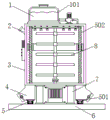
Fig. 1 is a schematic front view of a cross-sectional structure of the present invention;
FIG. 2 is a schematic side view of the cleaning mechanism of the present invention;
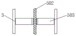
FIG. 3 is an enlarged side view of a partial section of the scraper according to the present invention;
fig. 4 is an enlarged schematic view of the front view partial section of the stirring mechanism of the present invention.
In the figure: 1. a cleaning mechanism; 101. a water tank; 102. a water pump; 103. a water pipe; 104. a spray head; 105. a water inlet; 2. a feed inlet; 3. a box body; 4. a discharge port; 5. a wall scraping mechanism; 501. a first servo motor; 502. a threaded rod; 503. a squeegee; 6. a base; 7. a support frame; 8. a stirring mechanism; 801. a motor base; 802. a second servo motor; 803. a stirring paddle; 804. a rotating shaft.
Detailed Description
The technical solutions in the embodiments of the present invention will be described clearly and completely with reference to the accompanying drawings in the embodiments of the present invention, and it is obvious that the described embodiments are only some embodiments of the present invention, not all embodiments. Based on the embodiments in the present invention, all other embodiments obtained by a person skilled in the art without creative work belong to the protection scope of the present invention.
Referring to fig. 1-4, the present invention provides an embodiment: a concrete storage device comprises a feeding port 2, a box body 3, a discharging port 4, a base 6 and a support frame 7, wherein the support frame 7 is uniformly and fixedly connected to the top end of the base 6, the box body 3 is fixedly connected to the top end of the support frame 7, the feeding port 2 is arranged at the top end of one side of the box body 3, the discharging port 4 is arranged on each of two sides of the bottom end of the box body 3, and a stirring mechanism 8 is arranged in the middle position of the bottom end of the box body 3;
a motor base 801, a second servo motor 802, a stirring paddle 803 and a rotating shaft 804 are sequentially arranged in the stirring mechanism 8, the motor base 801 is fixedly connected to the bottom end of the box body 3, the second servo motor 802 is arranged in the motor base 801, the model of the second servo motor 802 can be MR-J2S-10A, the rotating shaft 804 is fixedly connected to the top end of the second servo motor 802, the rotating shaft 804 penetrates through the box body 3, and the stirring paddle 803 is uniformly arranged on the outer side wall of the rotating shaft 804;
specifically, as shown in fig. 1 and 4, when the mechanism is used, first, the second servo motor 802 is started, and the rotation of the stirring paddle 803 is driven by the rotating shaft 804, so that the concrete inside the box body 3 always keeps fluidity;
the cleaning mechanism 1 is arranged at the top end inside the box body 3, the water tank 101, the water pump 102, the water pipe 103, the spray head 104 and the water inlet 105 are sequentially arranged inside the cleaning mechanism 1, the water tank 101 is fixedly connected to the top end of the box body 3, the water pump 102 is arranged on one side of the water tank 101, the type of the water pump 102 can be 300QSZ-3.4-13, the water pipe 103 is fixedly connected to the inside of the box body 3, one side of the top end of the water pipe 103 penetrates through the box body 3 and is fixedly connected with the water pump 102, the spray head 104 is uniformly and fixedly connected to the bottom end of the water pipe 103, and the;
specifically, as shown in fig. 1 and 2, when the mechanism is used, firstly, the water pump 102 is started, water which is placed in the water tank 101 in advance is sprayed out through the water pipe 103 and the spray head 104, and the interior of the box body 3 is cleaned simply and conveniently;
the two sides of the interior of the box body 3 are respectively provided with a wall scraping mechanism 5, the interior of the wall scraping mechanism 5 is sequentially provided with a first servo motor 501, a threaded rod 502 and a scraper 503, the first servo motors 501 are all arranged at the bottom end of the discharge port 4, the model of the first servo motor 501 can be ASD-A2, the top ends of the first servo motors 501 are all fixedly connected with the threaded rod 502, the threaded rods 502 are all penetrated through the interior of the discharge port 4 and fixedly connected with the top end of the interior of the box body 3, the outer side walls of the threaded rods 502 are all provided with the scraper 503, the interior of the scraper 503 is provided with internal threads, and the scraper 503 is in threaded connection;
specifically, as shown in fig. 1 and 4, when the mechanism is used, first, the first servo motor 501 is started to drive the threaded rod 502 to rotate, so that the scraper 503 moves up and down on the threaded rod 502 to clean the inner wall of the box 3, and waste is reduced.
The working principle is as follows: the utility model discloses when using, at first, pour into box 3 with the concrete through feed inlet 2, start second servo motor 802 after that, drive the rotation of stirring rake 803 through pivot 804 to make the inside concrete of box 3 keep mobility always, avoid the concrete to solidify in the certain time.
Afterwards, when needs use the concrete, open discharge gate 4 and release the concrete, start first servo motor 501 simultaneously, drive the rotation of threaded rod 502 to make scraper blade 503 reciprocate at threaded rod 502, clear up the inner wall of box 3, reduced extravagantly.
Finally, when the inside concrete of box 3 is whole releases, can start water pump 102, through water pipe 103 and shower nozzle 104 with place in advance in the water tank 101 water spray spill, to the inside washing of box 3, it is simple convenient, be convenient for next deposit, great increase the practicality of device.
It is obvious to a person skilled in the art that the invention is not restricted to details of the above-described exemplary embodiments, but that it can be implemented in other specific forms without departing from the spirit or essential characteristics of the invention. The present embodiments are therefore to be considered in all respects as illustrative and not restrictive, the scope of the invention being indicated by the appended claims rather than by the foregoing description, and all changes which come within the meaning and range of equivalency of the claims are therefore intended to be embraced therein. Any reference sign in a claim should not be construed as limiting the claim concerned.
Claims (6)
1. The utility model provides a strorage device of concrete, includes feed inlet (2), box (3), discharge gate (4), base (6) and support frame (7), its characterized in that: the even fixedly connected with support frame (7) in top of base (6), the top fixedly connected with box (3) of support frame (7), the top of box (3) one side is provided with feed inlet (2), the both sides of box (3) bottom all are provided with discharge gate (4), the intermediate position department of box (3) bottom is provided with rabbling mechanism (8), the inside top of box (3) is provided with wiper mechanism (1), the inside both sides of box (3) all are provided with scrapes wall mechanism (5).
2. A concrete storage unit as claimed in claim 1, wherein: the inside of wiper mechanism (1) has set gradually water tank (101), water pump (102), water pipe (103), shower nozzle (104) and water inlet (105), water tank (101) fixed connection is in the top of box (3), one side of water tank (101) is provided with water pump (102), water pipe (103) fixed connection is in the inside of box (3), and one side on water pipe (103) top runs through in box (3) and water pump (102) fixed connection.
3. A concrete storage unit as claimed in claim 2, wherein: the bottom end of the water pipe (103) is uniformly and fixedly connected with spray heads (104), and the spray heads (104) are distributed at equal intervals at the bottom end of the water pipe (103).
4. A concrete storage unit as claimed in claim 1, wherein: scrape the inside of wall mechanism (5) and set gradually first servo motor (501), threaded rod (502) and scraper blade (503), first servo motor (501) all set up in the bottom of discharge gate (4), the equal fixedly connected with threaded rod (502) in top of first servo motor (501), and threaded rod (502) all run through in the inside of discharge gate (4) and the inside top fixed connection of box (3), the lateral wall of threaded rod (502) all is provided with scraper blade (503).
5. A concrete storage unit as claimed in claim 4, wherein: the interior of the scraping plate (503) is provided with internal threads, and the scraping plate (503) is in threaded connection with the threaded rod (502).
6. A concrete storage unit as claimed in claim 1, wherein: the inside of rabbling mechanism (8) has set gradually motor cabinet (801), second servo motor (802), stirring rake (803) and pivot (804), motor cabinet (801) fixed connection is in the bottom of box (3), the inside of motor cabinet (801) is provided with second servo motor (802), the top fixedly connected with pivot (804) of second servo motor (802), and pivot (804) run through in the inside of box (3), the lateral wall of pivot (804) evenly is provided with stirring rake (803).
Priority Applications (1)
| Application Number | Priority Date | Filing Date | Title |
|---|---|---|---|
| CN202020395840.3U CN212096901U (en) | 2020-03-25 | 2020-03-25 | Concrete storage device |
Applications Claiming Priority (1)
| Application Number | Priority Date | Filing Date | Title |
|---|---|---|---|
| CN202020395840.3U CN212096901U (en) | 2020-03-25 | 2020-03-25 | Concrete storage device |
Publications (1)
| Publication Number | Publication Date |
|---|---|
| CN212096901U true CN212096901U (en) | 2020-12-08 |
Family
ID=73638279
Family Applications (1)
| Application Number | Title | Priority Date | Filing Date |
|---|---|---|---|
| CN202020395840.3U Active CN212096901U (en) | 2020-03-25 | 2020-03-25 | Concrete storage device |
Country Status (1)
| Country | Link |
|---|---|
| CN (1) | CN212096901U (en) |
Cited By (1)
| Publication number | Priority date | Publication date | Assignee | Title |
|---|---|---|---|---|
| CN114536555A (en) * | 2022-03-17 | 2022-05-27 | 中铁建工集团山东有限公司 | Building construction concrete mixing device |
-
2020
- 2020-03-25 CN CN202020395840.3U patent/CN212096901U/en active Active
Cited By (1)
| Publication number | Priority date | Publication date | Assignee | Title |
|---|---|---|---|---|
| CN114536555A (en) * | 2022-03-17 | 2022-05-27 | 中铁建工集团山东有限公司 | Building construction concrete mixing device |
Similar Documents
| Publication | Publication Date | Title |
|---|---|---|
| CN211389480U (en) | An easy-to-clean mixing mechanism for a concrete mixing station | |
| CN216831578U (en) | High-speed mixer convenient to wash | |
| CN215202700U (en) | Novel agitating unit is used to recycled concrete of self-cleaning | |
| CN215206560U (en) | Oil storage tank capable of automatically cleaning oil dirt | |
| CN221753024U (en) | Inner wall cleaning mechanism for mixer | |
| CN214211522U (en) | Washing box for sand washing of diamond | |
| CN119367819A (en) | A rapid defoaming equipment for detergent processing | |
| CN112109203A (en) | Self-cleaning building slurry stirring equipment in field of building machinery | |
| CN221095880U (en) | Concrete guniting device | |
| CN219899515U (en) | Cleaning mechanism for reaction kettle | |
| CN219466527U (en) | Mixer convenient to material loading | |
| CN216152717U (en) | Road construction concrete mortar agitated vessel | |
| CN216428373U (en) | A belt cleaning device that is used for hydraulic engineering sluice to have silt clearance function | |
| CN215463661U (en) | Stirring and blending device for oil chemical production | |
| CN211247681U (en) | Cleaning device for electrolytic cell | |
| CN211031219U (en) | Impurity removing device for production of heat shrinkable film | |
| CN210078993U (en) | Defeated filter equipment that uses of collection | |
| CN220030705U (en) | Vertical mixer for cement mortar | |
| CN219424296U (en) | Mixing equipment for producing soldering flux | |
| CN221410239U (en) | Poultry slaughtering and processing device | |
| CN220030696U (en) | Concrete tank convenient to clearance | |
| CN214556029U (en) | Waste scraping device for concrete mixing transport vehicle | |
| CN221414249U (en) | Washing device for expanded graphite | |
| CN217748306U (en) | Be used for high argillization degree coal to wash selection device | |
| CN218981323U (en) | A horizontal putty powder mixer |
Legal Events
| Date | Code | Title | Description |
|---|---|---|---|
| GR01 | Patent grant | ||
| GR01 | Patent grant |