CN112097597A - A size detection device for thin-walled parts - Google Patents
A size detection device for thin-walled parts Download PDFInfo
- Publication number
- CN112097597A CN112097597A CN202010974325.5A CN202010974325A CN112097597A CN 112097597 A CN112097597 A CN 112097597A CN 202010974325 A CN202010974325 A CN 202010974325A CN 112097597 A CN112097597 A CN 112097597A
- Authority
- CN
- China
- Prior art keywords
- measuring
- rod
- thin
- cross
- block
- Prior art date
- Legal status (The legal status is an assumption and is not a legal conclusion. Google has not performed a legal analysis and makes no representation as to the accuracy of the status listed.)
- Pending
Links
- 238000001514 detection method Methods 0.000 title claims abstract description 32
- 239000000758 substrate Substances 0.000 claims description 13
- 239000000523 sample Substances 0.000 abstract description 48
- 238000005259 measurement Methods 0.000 abstract description 38
- 238000012545 processing Methods 0.000 abstract description 4
- 238000010586 diagram Methods 0.000 description 9
- 238000004519 manufacturing process Methods 0.000 description 3
- 238000003754 machining Methods 0.000 description 2
- 238000000034 method Methods 0.000 description 2
- 230000009286 beneficial effect Effects 0.000 description 1
- 238000013461 design Methods 0.000 description 1
- 238000005516 engineering process Methods 0.000 description 1
- 238000012360 testing method Methods 0.000 description 1
Images


Classifications
-
- G—PHYSICS
- G01—MEASURING; TESTING
- G01B—MEASURING LENGTH, THICKNESS OR SIMILAR LINEAR DIMENSIONS; MEASURING ANGLES; MEASURING AREAS; MEASURING IRREGULARITIES OF SURFACES OR CONTOURS
- G01B5/00—Measuring arrangements characterised by the use of mechanical techniques
- G01B5/02—Measuring arrangements characterised by the use of mechanical techniques for measuring length, width or thickness
- G01B5/06—Measuring arrangements characterised by the use of mechanical techniques for measuring length, width or thickness for measuring thickness
- G01B5/061—Measuring arrangements characterised by the use of mechanical techniques for measuring length, width or thickness for measuring thickness height gauges
-
- G—PHYSICS
- G01—MEASURING; TESTING
- G01B—MEASURING LENGTH, THICKNESS OR SIMILAR LINEAR DIMENSIONS; MEASURING ANGLES; MEASURING AREAS; MEASURING IRREGULARITIES OF SURFACES OR CONTOURS
- G01B21/00—Measuring arrangements or details thereof, where the measuring technique is not covered by the other groups of this subclass, unspecified or not relevant
- G01B21/02—Measuring arrangements or details thereof, where the measuring technique is not covered by the other groups of this subclass, unspecified or not relevant for measuring length, width, or thickness
-
- G—PHYSICS
- G01—MEASURING; TESTING
- G01B—MEASURING LENGTH, THICKNESS OR SIMILAR LINEAR DIMENSIONS; MEASURING ANGLES; MEASURING AREAS; MEASURING IRREGULARITIES OF SURFACES OR CONTOURS
- G01B21/00—Measuring arrangements or details thereof, where the measuring technique is not covered by the other groups of this subclass, unspecified or not relevant
- G01B21/10—Measuring arrangements or details thereof, where the measuring technique is not covered by the other groups of this subclass, unspecified or not relevant for measuring diameters
Landscapes
- Physics & Mathematics (AREA)
- General Physics & Mathematics (AREA)
- A Measuring Device Byusing Mechanical Method (AREA)
Abstract
本发明属于机械加工检测设备技术领域,尤其涉及一种薄壁零件的尺寸检测装置,包括测量基板和主横杆,测量基板上滑动设有立柱和测量块,立柱和测量块的滑动方向在水平方向相互垂直设置,主横杆沿竖直方向与立柱滑动连接,立柱上设有刻度,主横杆上滑动设有副横杆一、副横杆二、测杆一和测杆二,副横杆一、副横杆二、测杆一和测杆二的滑动方向均与测量块的滑动方向一致,副横杆一上滑动设有测杆三,副横杆二上滑动设有测杆四,测杆三和测杆四的滑动方向均与立柱的滑动方向一致;测杆一上设有测头一,测杆二上设有测头二,测杆三上设有测头三,测杆四上设有测头四;测杆一和测杆二之间设有距离传感器一,测杆三和测杆四之间设有距离传感器二。

The invention belongs to the technical field of mechanical processing detection equipment, and in particular relates to a size detection device for thin-walled parts, comprising a measurement base plate and a main crossbar, a column and a measurement block are slidably arranged on the measurement base plate, and the sliding direction of the column and the measurement block is horizontal The directions are arranged perpendicular to each other, the main crossbar is slidingly connected with the column along the vertical direction, the column is provided with a scale, and the main crossbar is slid with the auxiliary crossbar I, the auxiliary crossbar, the measuring rod I and the measuring rod II. The sliding directions of rod 1, secondary cross rod 2, measuring rod 1 and measuring rod 2 are all the same as the sliding direction of the measuring block. , the sliding direction of measuring rod 3 and measuring rod 4 is consistent with the sliding direction of the column; A probe 4 is arranged on the rod 4; a distance sensor 1 is arranged between the measurement rod 1 and the measurement rod 2, and a distance sensor 2 is arranged between the measurement rod 3 and the measurement rod 4.
Description
技术领域technical field
本发明属于机械加工检测设备技术领域,尤其涉及一种薄壁零件的尺寸检测装置。The invention belongs to the technical field of mechanical processing detection equipment, and in particular relates to a size detection device for thin-walled parts.
背景技术Background technique
薄壁零件在机械设备中广泛应用,随着加工精度要求的不断提高,需要精确测量薄壁零件的各尺寸,如内孔截面呈圆形的圆形薄壁零件,需要检测其直径和底部厚度,或者内孔截面呈矩形的矩形薄壁零件,需要检测其长度、宽度和底部厚度。现有利用传统的测量装置,如游标卡尺等测量薄壁零件的各尺寸已经达不到生产要求,传统的测量装置测量薄壁零件的各尺寸存在测量精度低、测量效率低和测量局限等缺点。而若利用现有高精度测量仪器,如三坐标测量仪测量薄壁零件的各尺寸,虽然具有很高的测量精度,但测量成本高,不适合批量检测。Thin-walled parts are widely used in machinery and equipment. With the continuous improvement of machining accuracy requirements, it is necessary to accurately measure the dimensions of thin-walled parts. For example, circular thin-walled parts with a circular inner hole cross-section need to detect their diameter and bottom thickness. , or a rectangular thin-walled part with a rectangular inner hole section, its length, width and bottom thickness need to be detected. Existing use of traditional measuring devices, such as vernier calipers, to measure the dimensions of thin-walled parts can no longer meet production requirements. Traditional measuring devices to measure the dimensions of thin-walled parts have shortcomings such as low measurement accuracy, low measurement efficiency, and measurement limitations. However, if an existing high-precision measuring instrument, such as a three-coordinate measuring instrument, is used to measure the dimensions of thin-walled parts, although it has high measurement accuracy, the measurement cost is high, and it is not suitable for batch testing.
发明内容SUMMARY OF THE INVENTION
为解决现有技术存在的传统的测量装置测量薄壁零件各尺寸的测量精度低、测量效率低和测量局限的问题,本发明提供一种薄壁零件的尺寸检测装置。In order to solve the problems of low measurement accuracy, low measurement efficiency and measurement limitation existing in the prior art in measuring the dimensions of thin-walled parts by traditional measuring devices, the present invention provides a size detection device for thin-walled parts.
为解决上述技术问题,本发明所采用的技术方案如下,一种薄壁零件的尺寸检测装置,包括测量基板和主横杆,所述测量基板上滑动设置有立柱和测量块,所述立柱和测量块的滑动方向在水平方向相互垂直设置,所述主横杆沿竖直方向与立柱滑动连接,所述立柱上沿竖直方向设置有刻度,所述主横杆上滑动设置有副横杆一、副横杆二、测杆一和测杆二,且所述副横杆一、副横杆二、测杆一和测杆二的滑动方向均与测量块的滑动方向一致,所述副横杆一上滑动设置有测杆三,所述副横杆二上滑动设置有测杆四,且所述测杆三和测杆四的滑动方向均与立柱的滑动方向一致;所述测杆一上设置有测头一,所述测杆二上设置有测头二,所述测杆三上设置有测头三,所述测杆四上设置有测头四;所述测杆一和测杆二之间设置有距离传感器一,所述测杆三和测杆四之间设置有距离传感器二。In order to solve the above-mentioned technical problems, the technical solution adopted by the present invention is as follows. A size detection device for thin-walled parts includes a measurement substrate and a main crossbar, and a column and a measurement block are slidably arranged on the measurement substrate. The sliding directions of the measuring blocks are arranged vertically to each other in the horizontal direction, the main crossbar is slidably connected to the upright column along the vertical direction, the upright column is provided with a scale along the vertical direction, and the main crossbar is slidably provided with a
作为优选,所述测头一、测头二、测头三和测头四的工作面均呈矩形。提高各测头的工作面与薄壁零件的侧壁接触的可靠性和稳定性,提高该尺寸检测装置的检测精度。Preferably, the working surfaces of the first probe, the second probe, the third probe and the fourth probe are all rectangular. The reliability and stability of the contact between the working surface of each probe and the side wall of the thin-walled part are improved, and the detection accuracy of the size detection device is improved.
作为优选,所述测量块的截面呈方形。待测薄壁零件通过其内孔套设在测量块上,此时测量块的顶端与薄壁零件的内孔底端接触,截面呈方形的测量块,提高测量块支撑和定位薄壁零件的可靠性和稳定性,提高该尺寸检测装置的检测精度。Preferably, the cross section of the measuring block is square. The thin-walled part to be measured is sleeved on the measuring block through its inner hole. At this time, the top of the measuring block is in contact with the bottom end of the inner hole of the thin-walled part. The reliability and stability improve the detection accuracy of the size detection device.
作为优选,所述测量块的底端固定设置有支撑杆,所述支撑杆与测量基板滑动连接。因测量块用于支撑和定位待测薄壁零件,其工作面加工精度要求高,测量块通过支撑杆与测量基板滑动连接,便于测量块的加工制造,降低测量块的加工制造成本。Preferably, the bottom end of the measurement block is fixedly provided with a support rod, and the support rod is slidably connected with the measurement substrate. Because the measuring block is used to support and locate the thin-walled parts to be measured, its working surface requires high machining accuracy. The measuring block is slidably connected to the measuring substrate through the support rod, which facilitates the processing and manufacturing of the measuring block and reduces the processing and manufacturing cost of the measuring block.
作为优选,所述立柱和测量基板之间、支撑杆和测量基板之间、主横杆和立柱之间、副横杆一和主横杆之间、副横杆二和主横杆之间、测杆一和主横杆之间、测杆二和主横杆之间、测杆三和副横杆一之间,以及测杆四和副横杆二之间均通过滑动机构滑动连接,所述滑动机构包括十字滑槽和与十字滑槽配合的十字滑块;所述十字滑块和十字滑槽之间设置有锁紧件,所述锁紧件用于将十字滑块锁定在十字滑槽上。十字滑块沿十字滑槽滑动滑动精度高,即提高该尺寸检测装置的测量精度。Preferably, between the upright column and the measurement substrate, between the support bar and the measurement substrate, between the main crossbar and the upright column, between the first auxiliary crossbar and the main crossbar, between the second auxiliary crossbar and the main crossbar, Between the
进一步地,所述锁紧件包括两个锁紧螺钉,所述锁紧螺钉螺纹连接在十字滑块上,两个所述锁紧螺钉位于十字滑块的两侧,当所述锁紧螺钉拧紧时,所述锁紧螺钉抵靠在十字滑槽上。为保证测量的精度,当调整结束后,采用锁紧螺钉的形式将各十字滑块固定,防止读数出现偏差;且锁紧件的结构简单可靠,便于操作。Further, the locking member includes two locking screws, the locking screws are threadedly connected to the cross slide, and the two locking screws are located on both sides of the cross slide. When the locking screws are tightened , the locking screw abuts on the cross slot. In order to ensure the accuracy of measurement, when the adjustment is completed, the cross slides are fixed in the form of locking screws to prevent reading deviation; and the structure of the locking member is simple and reliable, and easy to operate.
进一步地,所述测量块和支撑杆之间、测头一和测杆一之间、测头二和测杆二之间、测头三和测杆三之间,以及测头四和测杆四之间分别通过螺杆固定连接。结构简单可靠,便于装配。Further, between the measuring block and the support rod, between the probe one and the probe rod one, between the probe two and the probe rod two, between the probe three and the probe rod three, and between the probe head four and the probe rod The four are respectively fixedly connected by screws. The structure is simple and reliable, and the assembly is convenient.
有益效果:本发明的薄壁零件的尺寸检测装置,结构简单可靠,设计巧妙,便于操作,成本低,待测薄壁零件只需一次装夹,可以得到如圆形薄壁零件的底部厚度和圆形薄壁零件的直径尺寸,或者矩形薄壁零件的底部厚度,以及矩形薄壁零件的长度和宽度尺寸,大大缩短测量时间,提高测量效率,同时不需反复装夹待测薄壁零件,提高测量精度;该薄壁零件的尺寸检测装置利用了传感技术,提高了测量精度,提高了自动化程度。Beneficial effects: The size detection device for thin-walled parts of the present invention has the advantages of simple and reliable structure, ingenious design, convenient operation and low cost. The diameter of round thin-walled parts, or the bottom thickness of rectangular thin-walled parts, as well as the length and width of rectangular thin-walled parts, greatly shortens the measurement time, improves measurement efficiency, and does not require repeated clamping of thin-walled parts to be measured. Improve the measurement accuracy; the size detection device of the thin-walled parts utilizes the sensing technology, improves the measurement accuracy, and improves the degree of automation.
附图说明Description of drawings
为了更清楚地说明本发明实施例的技术方案,下面将对实施例描述中所需要使用的附图作简单地介绍,显而易见地,下面描述中的附图仅仅是本发明的一些实施例,对于本领域的普通技术人员来讲,在不付出创造性劳动的前提下,还可以根据这些附图获得其它附图。In order to illustrate the technical solutions of the embodiments of the present invention more clearly, the following briefly introduces the accompanying drawings used in the description of the embodiments. Obviously, the drawings in the following description are only some embodiments of the present invention. For those of ordinary skill in the art, other drawings can also be obtained from these drawings without any creative effort.
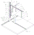
图1是本发明薄壁零件的尺寸检测装置的立体结构示意图;Fig. 1 is the three-dimensional structure schematic diagram of the size detection device of the thin-walled part of the present invention;
图2是本发明薄壁零件的尺寸检测装置的侧视示意图;Fig. 2 is the side view schematic diagram of the dimension detection device of the thin-walled part of the present invention;
图3是本发明薄壁零件的尺寸检测装置的圆形薄壁零件的立体结构示意图;Fig. 3 is the three-dimensional structure schematic diagram of the circular thin-walled part of the dimension detection device of the thin-walled part of the present invention;
图4是本发明薄壁零件的尺寸检测装置的矩形薄壁零件的立体结构示意图;Fig. 4 is the three-dimensional structure schematic diagram of the rectangular thin-walled part of the size detection device of the thin-walled part of the present invention;
图5是本发明测量测量块的高度时的状态示意图;Fig. 5 is the state schematic diagram when the present invention measures the height of the measuring block;
图6是本发明测量圆形薄壁零件的底部厚度时的状态示意图;Fig. 6 is the state schematic diagram when the present invention measures the bottom thickness of circular thin-walled parts;
图7是本发明测量圆形薄壁零件的直径时的状态示意图;Fig. 7 is the state schematic diagram when the present invention measures the diameter of the circular thin-walled part;
图8是本发明测量矩形薄壁零件的底部厚度时的状态示意图;Fig. 8 is the state schematic diagram when the present invention measures the bottom thickness of the rectangular thin-walled part;
图9是本发明测量矩形薄壁零件的长度和宽度时的状态示意图;Fig. 9 is the state schematic diagram when the present invention measures the length and width of rectangular thin-walled parts;
图中:1、测量基板,2、主横杆,3、立柱,4、刻度,5、测量块,6、副横杆一,7、副横杆二,8、测杆一,9、测杆二,10、测杆三,11、测杆四,12、测头一,13、测头二,14、测头三,15、测头四,16、距离传感器一,17、距离传感器二,18、支撑杆,19、滑动机构,19-1、十字滑槽,19-2、十字滑块,19-3、锁紧螺钉,20、螺杆;21、圆形薄壁零件,22、矩形薄壁零件。In the picture: 1. Measuring base plate, 2. Main crossbar, 3. Upright column, 4. Scale, 5. Measuring block, 6.
具体实施方式Detailed ways
下面将结合本发明实施例中的附图,对本发明实施例中的技术方案进行清楚、完整地描述,显然,所描述的实施例仅仅是本发明一部分实施例,而不是全部的实施例。以下对至少一个示例性实施例的描述实际上仅仅是说明性的,决不作为对本发明及其应用或使用的任何限制。基于本发明中的实施例,本领域普通技术人员在没有作出创造性劳动前提下所获得的所有其它实施例,都属于本发明保护的范围。The technical solutions in the embodiments of the present invention will be clearly and completely described below with reference to the accompanying drawings in the embodiments of the present invention. Obviously, the described embodiments are only a part of the embodiments of the present invention, but not all of the embodiments. The following description of at least one exemplary embodiment is merely illustrative in nature and is in no way intended to limit the invention, its application, or uses. Based on the embodiments of the present invention, all other embodiments obtained by those of ordinary skill in the art without creative efforts shall fall within the protection scope of the present invention.
实施例1Example 1
如图1和图2所示,一种薄壁零件的尺寸检测装置,包括测量基板1和主横杆2,所述测量基板1上滑动设置有立柱3和测量块5,所述立柱3和测量块5的滑动方向在水平方向相互垂直设置,本实施例的所述测量块5的底端固定设置有支撑杆18,其通过所述支撑杆18与测量基板1滑动连接,所述主横杆2沿竖直方向与立柱3滑动连接,所述立柱3上沿竖直方向设置有刻度4,所述主横杆2上滑动设置有副横杆一6、副横杆二7、测杆一8和测杆二9,且所述副横杆一6、副横杆二7、测杆一8和测杆二9的滑动方向均与测量块5的滑动方向一致,所述副横杆一6上滑动设置有测杆三10,所述副横杆二7上滑动设置有测杆四11,且所述测杆三10和测杆四11的滑动方向均与立柱3的滑动方向一致;所述测杆一8上设置有测头一12,所述测杆二9上设置有测头二13,所述测杆三10上设置有测头三14,所述测杆四11上设置有测头四15;所述测杆一8和测杆二9之间设置有距离传感器一16,所述测杆三10和测杆四11之间设置有距离传感器二17。As shown in FIG. 1 and FIG. 2 , a size detection device for thin-walled parts includes a
如图1所示,为了提高该尺寸检测装置的可靠性和稳定性,提高该尺寸检测装置的检测精度,所述测头一12、测头二13、测头三14和测头四15的工作面均呈矩形。所述测量块5的截面呈方形。As shown in FIG. 1 , in order to improve the reliability and stability of the size detection device and improve the detection accuracy of the size detection device, the
如图1所示,为了该尺寸检测装置便于操作,以及提高该尺寸检测装置的各部件的滑动精度,所述立柱3和测量基板1之间、支撑杆18和测量基板1之间、主横杆2和立柱3之间、副横杆一6和主横杆2之间、副横杆二7和主横杆2之间、测杆一8和主横杆2之间、测杆二9和主横杆2之间、测杆三10和副横杆一6之间,以及测杆四11和副横杆二7之间均通过滑动机构19滑动连接,所述滑动机构19包括十字滑槽19-1和与十字滑槽19-1配合的十字滑块19-2;所述十字滑块19-2和十字滑槽19-1之间设置有锁紧件,所述锁紧件用于将十字滑块19-2锁定在十字滑槽19-1上。本实施例的所述锁紧件包括两个锁紧螺钉19-3,所述锁紧螺钉19-3螺纹连接在十字滑块19-2上,两个所述锁紧螺钉19-3位于十字滑块19-2的两侧,当所述锁紧螺钉19-3拧紧时,所述锁紧螺钉19-3抵靠在十字滑槽19-1上。As shown in FIG. 1 , in order to facilitate the operation of the size detection device and to improve the sliding accuracy of each component of the size detection device, between the
如图1和图2所示,本实施例的所述测量块5和支撑杆18之间、测头一12和测杆一8之间、测头二13和测杆二9之间、测头三14和测杆三10之间,以及测头四15和测杆四11之间分别通过螺杆20固定连接,通过螺杆20这种螺纹固定连接方式,结构简单可靠,便于装配。As shown in FIG. 1 and FIG. 2 , in this embodiment, between the measuring
如图3和图4所示,本实施例待测量的零件有内孔截面呈圆形的圆形薄壁零件21和内孔截面呈矩形的矩形薄壁零件22。As shown in FIGS. 3 and 4 , the parts to be measured in this embodiment include a circular thin-
该薄壁零件的尺寸检测装置的工作步骤如下:The working steps of the size detection device for thin-walled parts are as follows:
(1)、将该尺寸检测装置放置于测量平台上,此时测量基板1的底端与测量平台接触;(1), place the size detection device on the measurement platform, and the bottom end of the
(2)、如图5所示,当测量测量块5的高度时,首先依次滑动调节立柱3、主横杆2和测杆一8的位置,直至测头一12与测量块5的顶端接触,此时读取立柱3上的刻度值,得出测量块5的高度,再将测头一12复位;(2) As shown in Figure 5, when measuring the height of the measuring
(3)、如图6所示,当测量圆形薄壁零件21的底部厚度时,首先将圆形薄壁零件21通过其内孔套设在测量块5上,此时测量块5的顶端与圆形薄壁零件21的内孔底端接触,再依次滑动调节立柱3、主横杆2和测杆一8的位置,直至测头一12与圆形薄壁零件21的底端接触,此时读取立柱3上的刻度值,并减去步骤(2)中测量块5的高度,得出圆形薄壁零件21的底部厚度,再将测头一12复位;(3) As shown in Figure 6, when measuring the bottom thickness of the circular thin-
(4)、如图7所示,当测量圆形薄壁零件21的直径时,依次滑动调节立柱3、主横杆2、测杆一8、测杆二9、副横杆一6、副横杆二7、测杆三10和测杆四11的位置,直至测头一12和测头二13位于圆形薄壁零件21的两侧并经过其直径,测头三14和测头四15也位于圆形薄壁零件21的两侧并经过其直径,此时距离传感器一16和距离传感器二17均测得圆形薄壁零件21的直径,并求其平均值;(4) As shown in Figure 7, when measuring the diameter of the circular thin-
(5)、如图8所示,当测量矩形薄壁零件22的底部厚度时,首先将矩形薄壁零件22通过其内孔套设在测量块5上,此时测量块5的顶端与圆形薄壁零件21的内孔底端接触,再依次滑动调节立柱3、主横杆2和测杆一8的位置,直至测头一12与矩形薄壁零件22的底端接触,此时读取立柱3上的刻度值,并减去步骤(2)中测量块5的高度,得出矩形薄壁零件22的底部厚度,再将测头一12复位;(5) As shown in Figure 8, when measuring the bottom thickness of the rectangular thin-
(6)、如图9所示,当测量矩形薄壁零件22的长度和宽度时,依次滑动调节立柱3、主横杆2、测杆一8、测杆二9、副横杆一6、副横杆二7、测杆三10和测杆四11的位置,直至测头一12和测头二13位于矩形薄壁零件22的两侧,测头三14和测头四15位于矩形薄壁零件22的两侧,此时距离传感器一16测得矩形薄壁零件22的长度,距离传感器二17测得矩形薄壁零件22的宽度。(6) As shown in Figure 9, when measuring the length and width of the rectangular thin-
上述步骤(2)~(6)中,立柱3、主横杆2、测杆一8、测杆二9、副横杆一6、副横杆二7、测杆三10和测杆四11滑动调节到位后,分别通过拧紧对应的锁紧螺钉19-3进行锁紧定位。In the above steps (2) to (6), the
通过上述步骤,可以得到圆形薄壁零件21的底部厚度、圆形薄壁零件21的直径、矩形薄壁零件22的底部厚度,以及矩形薄壁零件22的长度和宽度尺寸。Through the above steps, the bottom thickness of the circular thin-
以上,仅为本发明较佳的具体实施方式,但本发明的保护范围并不局限于此,任何熟悉本技术领域的技术人员在本发明揭露的技术范围内,根据本发明的技术方案及其发明构思加以等同替换或改变,都应涵盖在本发明的保护范围之内。The above are only preferred specific embodiments of the present invention, but the protection scope of the present invention is not limited thereto. Equivalent replacements or changes to the inventive concept shall all fall within the protection scope of the present invention.
Claims (7)
Priority Applications (1)
| Application Number | Priority Date | Filing Date | Title |
|---|---|---|---|
| CN202010974325.5A CN112097597A (en) | 2020-09-16 | 2020-09-16 | A size detection device for thin-walled parts |
Applications Claiming Priority (1)
| Application Number | Priority Date | Filing Date | Title |
|---|---|---|---|
| CN202010974325.5A CN112097597A (en) | 2020-09-16 | 2020-09-16 | A size detection device for thin-walled parts |
Publications (1)
| Publication Number | Publication Date |
|---|---|
| CN112097597A true CN112097597A (en) | 2020-12-18 |
Family
ID=73760248
Family Applications (1)
| Application Number | Title | Priority Date | Filing Date |
|---|---|---|---|
| CN202010974325.5A Pending CN112097597A (en) | 2020-09-16 | 2020-09-16 | A size detection device for thin-walled parts |
Country Status (1)
| Country | Link |
|---|---|
| CN (1) | CN112097597A (en) |
Cited By (1)
| Publication number | Priority date | Publication date | Assignee | Title |
|---|---|---|---|---|
| CN115179067A (en) * | 2022-07-08 | 2022-10-14 | 江阴市恒润环锻有限公司 | Thin-wall flange piece fixing equipment based on flexible positioning locking type |
Citations (13)
| Publication number | Priority date | Publication date | Assignee | Title |
|---|---|---|---|---|
| US20010020336A1 (en) * | 2000-03-13 | 2001-09-13 | Ryoichi Tadaki | Apparatus for measuring height of mounting positions of cutting knife and pressure bar in veneer lathe |
| CN101806569A (en) * | 2010-04-19 | 2010-08-18 | 常州亿晶光电科技有限公司 | Tool for measuring thickness of lamination part of solar cell |
| CN204100955U (en) * | 2014-08-19 | 2015-01-14 | 襄阳南车电机技术有限公司 | A kind of multi-usage height gauge |
| CN104567601A (en) * | 2015-01-06 | 2015-04-29 | 山东高强紧固件有限公司 | Cylindrical standard component end face thickness detecting tool |
| CN206556528U (en) * | 2017-03-09 | 2017-10-13 | 阜阳冈奇电子有限公司 | Novel high chi |
| CN109443158A (en) * | 2018-12-26 | 2019-03-08 | 贵州凯星液力传动机械有限公司 | A kind of measuring device and its test method of deep-hole parts bottom hole wall thickness dimension |
| CN209524854U (en) * | 2019-05-06 | 2019-10-22 | 广西玉柴机器股份有限公司 | A kind of device measuring pipe wall thickness |
| CN210089569U (en) * | 2019-08-22 | 2020-02-18 | 西安工业大学 | A multi-degree-of-freedom component height detection device |
| CN111089555A (en) * | 2019-12-12 | 2020-05-01 | 江苏理工学院 | A diameter and length detection device of a stepped shaft |
| CN111174741A (en) * | 2020-01-21 | 2020-05-19 | 江苏理工学院 | Measuring device for cylindrical part with inner hole |
| CN111174661A (en) * | 2020-01-21 | 2020-05-19 | 江苏理工学院 | Hole center distance measuring device for vertically intersected holes |
| CN210603094U (en) * | 2019-11-26 | 2020-05-22 | 夏创德 | Simple bottom measuring ruler |
| CN111578896A (en) * | 2020-04-23 | 2020-08-25 | 中铁十六局集团有限公司 | Auxiliary appliance for measuring adjustment elevation of segmental beam and beam segment |
-
2020
- 2020-09-16 CN CN202010974325.5A patent/CN112097597A/en active Pending
Patent Citations (13)
| Publication number | Priority date | Publication date | Assignee | Title |
|---|---|---|---|---|
| US20010020336A1 (en) * | 2000-03-13 | 2001-09-13 | Ryoichi Tadaki | Apparatus for measuring height of mounting positions of cutting knife and pressure bar in veneer lathe |
| CN101806569A (en) * | 2010-04-19 | 2010-08-18 | 常州亿晶光电科技有限公司 | Tool for measuring thickness of lamination part of solar cell |
| CN204100955U (en) * | 2014-08-19 | 2015-01-14 | 襄阳南车电机技术有限公司 | A kind of multi-usage height gauge |
| CN104567601A (en) * | 2015-01-06 | 2015-04-29 | 山东高强紧固件有限公司 | Cylindrical standard component end face thickness detecting tool |
| CN206556528U (en) * | 2017-03-09 | 2017-10-13 | 阜阳冈奇电子有限公司 | Novel high chi |
| CN109443158A (en) * | 2018-12-26 | 2019-03-08 | 贵州凯星液力传动机械有限公司 | A kind of measuring device and its test method of deep-hole parts bottom hole wall thickness dimension |
| CN209524854U (en) * | 2019-05-06 | 2019-10-22 | 广西玉柴机器股份有限公司 | A kind of device measuring pipe wall thickness |
| CN210089569U (en) * | 2019-08-22 | 2020-02-18 | 西安工业大学 | A multi-degree-of-freedom component height detection device |
| CN210603094U (en) * | 2019-11-26 | 2020-05-22 | 夏创德 | Simple bottom measuring ruler |
| CN111089555A (en) * | 2019-12-12 | 2020-05-01 | 江苏理工学院 | A diameter and length detection device of a stepped shaft |
| CN111174741A (en) * | 2020-01-21 | 2020-05-19 | 江苏理工学院 | Measuring device for cylindrical part with inner hole |
| CN111174661A (en) * | 2020-01-21 | 2020-05-19 | 江苏理工学院 | Hole center distance measuring device for vertically intersected holes |
| CN111578896A (en) * | 2020-04-23 | 2020-08-25 | 中铁十六局集团有限公司 | Auxiliary appliance for measuring adjustment elevation of segmental beam and beam segment |
Cited By (2)
| Publication number | Priority date | Publication date | Assignee | Title |
|---|---|---|---|---|
| CN115179067A (en) * | 2022-07-08 | 2022-10-14 | 江阴市恒润环锻有限公司 | Thin-wall flange piece fixing equipment based on flexible positioning locking type |
| CN115179067B (en) * | 2022-07-08 | 2023-09-22 | 江阴市恒润环锻有限公司 | Thin-wall flange part fixing equipment based on flexible positioning locking |
Similar Documents
| Publication | Publication Date | Title |
|---|---|---|
| CN202158818U (en) | Simple and convenient multipurpose detection platform | |
| CN109357600B (en) | Taper detection device for taper hole | |
| CN203443509U (en) | Checking fixture for machine tool track | |
| CN111811363A (en) | A measuring device for measuring the size of V-shaped grooves | |
| CN206037856U (en) | Calibrating installation who can be used to examination of wedge clearance gauge and inside and outside right angle detection ruler | |
| CN109373868A (en) | A kind of plane inclined hole angle detection device and detection method | |
| CN112097597A (en) | A size detection device for thin-walled parts | |
| CN105115470A (en) | Tool of quickly detecting unevenness of steel plate | |
| CN104330009A (en) | Component height size measuring method and measuring tool thereof | |
| CN113720233A (en) | Device for measuring size of cuboid inclined plane | |
| CN111174661B (en) | A hole center distance measuring device for vertically intersecting holes | |
| CN208860241U (en) | A kind of dial gauge calibrating installation | |
| CN110307818A (en) | A measuring device for step plane distance and hole depth | |
| CN201392182Y (en) | Guide rail linear deflection precision detection device based on optical lever | |
| CN110514167A (en) | A testing tool for taper and major diameter of taper hole | |
| CN206756061U (en) | A kind of adjustable tile thickness measuring instrument | |
| CN112097720A (en) | Detection apparatus for tapering and tip diameter of cone part | |
| CN112097593A (en) | Inspection device for measuring the dimensions of guide rails | |
| CN116222375A (en) | Non-contact size detection device for small and medium-sized bearings | |
| CN209727022U (en) | The detection device of casing magazine well and casing large trough symmetry | |
| CN207866178U (en) | A kind of sliding block perpendicularity detection tool | |
| CN108592758B (en) | A hole distance detection device | |
| CN215639250U (en) | Flatness measuring device | |
| CN205561712U (en) | High verifying attachment of supporting rack | |
| CN220670359U (en) | An anchor bolt inspection caliper that can determine the error range |
Legal Events
| Date | Code | Title | Description |
|---|---|---|---|
| PB01 | Publication | ||
| PB01 | Publication | ||
| SE01 | Entry into force of request for substantive examination | ||
| SE01 | Entry into force of request for substantive examination | ||
| RJ01 | Rejection of invention patent application after publication | ||
| RJ01 | Rejection of invention patent application after publication |
Application publication date: 20201218 |