CN113720233A - Device for measuring size of cuboid inclined plane - Google Patents
Device for measuring size of cuboid inclined plane Download PDFInfo
- Publication number
- CN113720233A CN113720233A CN202110958487.4A CN202110958487A CN113720233A CN 113720233 A CN113720233 A CN 113720233A CN 202110958487 A CN202110958487 A CN 202110958487A CN 113720233 A CN113720233 A CN 113720233A
- Authority
- CN
- China
- Prior art keywords
- measuring
- block
- bottom plate
- measuring block
- angle
- Prior art date
- Legal status (The legal status is an assumption and is not a legal conclusion. Google has not performed a legal analysis and makes no representation as to the accuracy of the status listed.)
- Granted
Links
- 230000007246 mechanism Effects 0.000 claims abstract description 102
- 238000005259 measurement Methods 0.000 claims abstract description 16
- 238000000034 method Methods 0.000 claims abstract description 10
- 238000006073 displacement reaction Methods 0.000 claims description 4
- 230000008859 change Effects 0.000 claims description 3
- 230000008569 process Effects 0.000 abstract description 6
- 230000000694 effects Effects 0.000 abstract description 4
- 238000003754 machining Methods 0.000 abstract description 2
- 238000010586 diagram Methods 0.000 description 8
- 230000008901 benefit Effects 0.000 description 2
- 238000010276 construction Methods 0.000 description 2
- 238000001514 detection method Methods 0.000 description 2
- 230000007547 defect Effects 0.000 description 1
- 238000012986 modification Methods 0.000 description 1
- 230000004048 modification Effects 0.000 description 1
- 238000004513 sizing Methods 0.000 description 1
- 238000006467 substitution reaction Methods 0.000 description 1
Images




Classifications
-
- G—PHYSICS
- G01—MEASURING; TESTING
- G01B—MEASURING LENGTH, THICKNESS OR SIMILAR LINEAR DIMENSIONS; MEASURING ANGLES; MEASURING AREAS; MEASURING IRREGULARITIES OF SURFACES OR CONTOURS
- G01B5/00—Measuring arrangements characterised by the use of mechanical techniques
-
- G—PHYSICS
- G01—MEASURING; TESTING
- G01B—MEASURING LENGTH, THICKNESS OR SIMILAR LINEAR DIMENSIONS; MEASURING ANGLES; MEASURING AREAS; MEASURING IRREGULARITIES OF SURFACES OR CONTOURS
- G01B5/00—Measuring arrangements characterised by the use of mechanical techniques
- G01B5/02—Measuring arrangements characterised by the use of mechanical techniques for measuring length, width or thickness
- G01B5/06—Measuring arrangements characterised by the use of mechanical techniques for measuring length, width or thickness for measuring thickness
- G01B5/061—Measuring arrangements characterised by the use of mechanical techniques for measuring length, width or thickness for measuring thickness height gauges
-
- G—PHYSICS
- G01—MEASURING; TESTING
- G01B—MEASURING LENGTH, THICKNESS OR SIMILAR LINEAR DIMENSIONS; MEASURING ANGLES; MEASURING AREAS; MEASURING IRREGULARITIES OF SURFACES OR CONTOURS
- G01B5/00—Measuring arrangements characterised by the use of mechanical techniques
- G01B5/24—Measuring arrangements characterised by the use of mechanical techniques for measuring angles or tapers; for testing the alignment of axes
Landscapes
- Physics & Mathematics (AREA)
- General Physics & Mathematics (AREA)
- A Measuring Device Byusing Mechanical Method (AREA)
Abstract
The invention relates to a device for measuring the size of a cuboid inclined plane, belonging to the technical field of machining; the method comprises the following steps: a height coarse adjustment mechanism (A), an angle adjustment mechanism (B), a measuring block leveling mechanism (C), a measuring mechanism (D) and a zeroing mechanism (E); the height coarse adjustment mechanism coarsely adjusts the distance between the top plate and the bottom plate according to the height of the part; the angle adjusting mechanism obtains the angle of the part by adjusting the supporting guide rail on the bottom plate; the leveling mechanism adjusts the measuring block to be parallel to the standard block; the measuring mechanism obtains the height value of the part by adjusting the measuring block to be in close contact with the part; after the zero setting mechanism coarsely adjusts the height and the angle and levels the measuring block, the scale is reset to zero before measurement; the height coarse adjustment mechanism is respectively connected with the angle adjustment mechanism, the measuring block leveling mechanism and the zero adjustment mechanism, and the measuring mechanism is connected with the leveling mechanism. Compared with the prior art, the device has the effects of simple operation process, wide application range (capable of detecting different part specifications) and high working efficiency.
Description
Technical Field
The invention relates to a size measuring device, in particular to a device for measuring the size of a cuboid inclined plane, and belongs to the technical field of machining.
Background
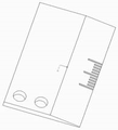
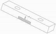
At the present stage, the measurement of the upper inclined planes of wedge-shaped parts of various models is performed, because the size precision of the inclined planes of the parts is high, and after the finished products are processed, the big end and the small end of the parts are processed, the angle of the parts and the size of the big end of the inclined planes cannot be measured by using conventional measuring tools (vernier calipers, angle rulers and the like), as shown in fig. 1, the measurement is a structural schematic diagram of the wedge-shaped parts, and the wedge-shaped parts are further processed according with the requirements of the parts on the basis of the size of the wedge-shaped appearance standard block shown in fig. 2; therefore, a special measuring device needs to be designed and manufactured to measure the sizes of the inclined plane and the large head of the part.
Disclosure of Invention
The invention aims to overcome the defects of the prior art and provides a device for measuring the size of a cuboid inclined plane, which can detect whether the heights and angles of the inclined planes of wedge-shaped parts with different specifications are qualified or not and can measure specific numerical values.
The purpose of the invention is realized by the following technical scheme.
An apparatus for cuboid bevel sizing comprising: the device comprises a height coarse adjustment mechanism, an angle adjustment mechanism, a measuring block leveling mechanism, a measuring mechanism and a zeroing mechanism;
the height coarse adjustment mechanism is used for coarsely adjusting the distance between the top plate and the bottom plate of the device according to the height of the part;
the angle adjusting mechanism is used for acquiring the inclined plane angle value of the part by adjusting the angle of an element supporting the inclined plane of the part on the bottom plate;
the measuring block leveling mechanism is used for adjusting the measuring block arranged on the lower plane of the top plate to enable the lower plane of the measuring block to be parallel to the upper plane of the standard block of the part;
the measuring mechanism is used for obtaining the height value of the part after the measuring block is adjusted to be in close contact with the part;
the zero setting mechanism is used for resetting the scales on the device to zero before measurement after the height and the angle are adjusted roughly and the measuring block is leveled;
the height coarse adjustment mechanism is respectively connected with the angle adjustment mechanism, the measuring block leveling mechanism and the zero adjustment mechanism, and the measuring mechanism is connected with the measuring block leveling mechanism.
Preferably, the height coarse adjustment mechanism coarsely adjusts the distance between the top plate and the bottom plate by combining the heights of the components by pushing and pulling the push-pull screw rod by using a four-bar linkage principle.
Preferably, the height coarse adjustment mechanism comprises the bottom plate, the top plate, a push-pull screw, a roller shaft, a roller, a sliding block and a bracket; the bottom plate and the top plate are rotatably connected through two pairs of supports distributed on two sides, wherein each pair of supports are in crossed rotatable connection, two ends of a roller shaft are respectively sleeved with a roller and then are arranged at the front end of the bottom plate, two sides of the roller shaft are respectively rotatably connected with the lower end of one support, 2 sliding blocks are respectively slidably arranged at the front ends of two sides of the top plate, each sliding block is respectively rotatably connected with the upper end of one support, and a push-pull screw rod is fixedly connected to the roller shaft and can drive the roller shaft to move back and forth.
Preferably, the fixed connection is through a pin connection, the rotatable connection is through a pin connection, and the sliding connection is through a T-shaped groove connection formed in the top plate for placing the slider thereon.
Preferably, the roller is arranged in a roller groove formed in the bottom plate, two ends of the roller shaft are arranged in long grooves on two side surfaces of the bottom plate, and one end of the push-pull screw rod, which is far away from the roller shaft, is movably connected to the vertical plate at the rear end of the bottom plate.
Preferably, the angle adjusting mechanism comprises a support guide rail, an adjusting screw, a fastening screw and an index; the supporting guide rail is used for tightly fitting and supporting the part inclined plane by adjusting the angle between the supporting guide rail and the bottom plate, the middle part of the supporting guide rail is rotatably connected to the bottom plate, the flange of the bottom plate above the connecting shaft is fixedly connected with an index, the scale on the supporting guide rail is read through an index indication arrow to obtain the angle of the part inclined plane, the supporting guide rail is used for adjusting the angle between the supporting guide rail and the bottom plate by installing adjusting screws on the supporting guide rail, and the supporting guide rail is locked on the bottom plate after the angle is adjusted in place by fastening screws.
Preferably, the connection part of the index and the bottom plate flange is adjustable so as to conveniently measure the inclined planes of parts with different specifications.
Preferably, the measuring block leveling mechanism includes: the device comprises a measuring block support, a fastening screw, a measuring knob, an adjusting screw and a measuring block; the measuring block support is hung on the top plate through a fastening screw, the leveling mechanism of the measuring block is adjusted through an adjusting screw which is arranged on the top plate and abuts against the upper plane of the measuring block support, the measuring knob penetrates through a threaded hole in the measuring block support and is connected with the measuring block through a pin
Preferably, the measuring mechanism includes: the scale comprises a first scale block and a second scale block; the first scale block is fixed on the measuring block, the second scale block is fixed on the measuring block support, and the first scale block and the second scale block generate corresponding relative displacement along with the position change between the measuring block support and the measuring block.
Preferably, the zero setting mechanism comprises a positioning screw and a locking nut; the positioning screw is arranged in a threaded hole in the vertical plate at the rear end of the bottom plate and used for adjusting the front and rear positions of the standard block of the part in the measuring device, and the locking nut is used for locking the positioning screw after the position of the standard block is adjusted.
Advantageous effects
Compared with the prior art, the device can easily obtain the conclusion whether the part is qualified or not through the angle and height indicating values according to the error requirement of the part, and can further obtain the specific error value of the part, so that the measurement precision is high, and a user can further process the part. The device has the effects of simple operation process, wide application range (detection on different part specifications) and high working efficiency.
Drawings
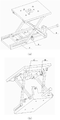
FIG. 1 is a schematic perspective view of the apparatus of the present invention; wherein, (a) is a front top view, and (b) is a rear elevation view;
FIG. 2 is a schematic structural diagram of a part to be tested;
FIG. 3 is a schematic diagram of a standard block structure;
FIG. 4 is a schematic structural view of a height coarse adjustment mechanism;
FIG. 5 is a schematic view of a bottom plate structure;
FIG. 6 is a schematic view of the top plate construction;
FIG. 7 is a schematic view of a roller shaft with rollers;
FIG. 8 is a schematic view of a push-pull screw structure;
FIG. 9 is a schematic view of a slider structure;
FIG. 10 is a schematic view of the angle adjustment mechanism;
FIG. 11 is a schematic view of a support rail configuration;
FIG. 12 is a schematic diagram of the index structure;
FIG. 13 is a schematic structural view of a leveling mechanism of the measuring block;
FIG. 14 is a structural schematic view of a leveling mechanism with a top plate;
FIG. 15 is a schematic view of a support structure of the measuring block;
FIG. 16 is a schematic diagram of a measurement block structure;
FIG. 17 is a schematic view of a measuring knob;
FIG. 18 is a schematic view of a measuring mechanism;
FIG. 19 is a schematic diagram of a first scale block structure;
FIG. 20 is a schematic diagram of a second scale block structure;
FIG. 21 is a schematic view of the zeroing mechanism;
FIG. 22 is a schematic view of a part measurement height reading;
FIG. 23 is a schematic view of a part measurement angle reading;
reference numerals: the device comprises an A-height coarse adjustment mechanism, a B-angle adjustment mechanism, a C-measuring block leveling mechanism, a D-measuring mechanism, an E-zero adjustment mechanism, a 1-bottom plate, a 2-top plate, a 3-push-pull screw, a 4-roller shaft, a 5-roller, a 6-pin shaft, a 7-sliding block, an 8-bracket, a 12-pin, a 13-supporting guide rail, a 14-adjusting screw, a 15-fastening screw, a 16-index, a 17-index screw, a 19-measuring block support, a 21-measuring knob, a 23-measuring block, a 25-first scale block, a 26-second scale block, a 28-positioning screw and a 29-locking nut.
Detailed Description
For the purpose of illustrating the objects, technical solutions and advantages of the embodiments of the present invention, the technical solutions in the embodiments of the present invention will be clearly and completely described below with reference to the accompanying drawings in the embodiments of the present invention.
An embodiment of the invention will now be described by way of example of a wedge-shaped element as shown in figure 2, as shown in figure 3 for a standard block of its external profile dimensions.
Example 1
As shown in fig. 1, a device for measuring the size of a cuboid slope comprises: the device comprises a height coarse adjustment mechanism A, an angle adjustment mechanism B, a measuring block leveling mechanism C, a measuring mechanism D and a return-to-zero mechanism E;
1. the height coarse adjustment mechanism A is used for coarsely adjusting the distance between the top plate and the bottom plate of the device according to the height of the part;
2. the angle adjusting mechanism B is used for acquiring the inclined plane angle value of the part by adjusting the angle of an element supporting the inclined plane of the part on the bottom plate;
3. the measuring block leveling mechanism C is used for adjusting the measuring block arranged on the lower plane of the top plate to enable the lower plane of the measuring block to be parallel to the upper plane of the standard block of the part;
4. the measuring mechanism D is used for obtaining the height value of the part after the measuring block is adjusted to be in close contact with the part;
5. and the zero setting mechanism E is used for resetting the scale on the device to zero before measurement after the height and the angle are adjusted roughly and the measuring block is leveled.
The height coarse adjustment mechanism A is respectively connected with the angle adjustment mechanism B, the measuring block leveling mechanism C and the zero adjustment mechanism E, and the measuring mechanism D is connected with the measuring block leveling mechanism C.
1. As a better realization mode of the height coarse adjustment mechanism A, the distance between the top plate and the bottom plate is coarsely adjusted by utilizing the four-bar principle and combining the height of parts through the pushing and pulling of the push-pull screw rod. The specific structure is shown in fig. 4, and comprises: the device comprises a bottom plate 1, a top plate 2, a push-pull screw 3, a roller shaft 4, a roller 5, a sliding block 7 and a bracket 8;
the bottom plate 1 and the top plate 2 are rotatably connected through two pairs of supports 8 distributed on two sides, wherein each pair of supports 8 are in cross rotatable connection, two ends of a roller shaft 4 are respectively sleeved with a roller 5 and then are arranged at the front end of the bottom plate 1, two sides of the roller shaft 4 are respectively rotatably connected with the lower end of one support 8, 2 sliding blocks 7 are respectively slidably arranged at the front ends of two sides of the top plate 2, each sliding block 7 is respectively rotatably connected with the upper end of one support 8, and a push-pull screw rod 3 is fixedly connected to the roller shaft 4 and can drive the roller shaft 4 to move back and forth.
Further, for convenience, the fixed connection is through a pin 12, the rotatable connection is through a pin, and the sliding connection is through a T-shaped groove formed in the top plate 2 and used for placing the sliding block 7. Furthermore, the connection of the push-pull screw 3 and the roller shaft 4 by the pin 12 has the advantage that both are relatively fixed in position and the push-pull screw 3 is freely rotatable relative to the roller shaft 4.
Further, in order to improve the stability of the forward and backward movement of the roller shaft 4 and the alignment limit, the roller 5 is disposed in a roller groove formed on the bottom plate 1, two ends of the roller shaft 4 are mounted in long grooves on two side surfaces of the bottom plate 1, and one end of the push-pull screw 3, which is far away from the roller shaft 4, is movably connected to a vertical plate at the rear end of the bottom plate 1. Preferably a threaded connection, on the one hand the amount of forward and backward movement of the roller shaft 4 can be finely controlled and on the other hand it can be adjusted so that it does not move back and forth.
When the rotary push-pull screw rod 3 moves forwards, the roller shaft 4 and the sliding block 7 move forwards, the included angle alpha of the bracket is increased, the distance between the top plate and the bottom plate is reduced, and otherwise, the distance between the top plate and the bottom plate is increased; in this way, the distance between the top plate 2 and the bottom plate 1 can be adjusted according to the height of the component.
The preferred bottom plate structure is shown in fig. 5, the top plate structure is shown in fig. 6, the roller shaft structure with rollers is shown in fig. 7, the push-pull screw structure is shown in fig. 8, and the slider structure is shown in fig. 9;
2. as a preferred embodiment of the angle adjustment mechanism B, as shown in fig. 10, the angle adjustment mechanism B includes: a support guide rail 13, an adjusting screw 14, a fastening screw 15 and an index 16; the supporting guide rail 13 is used for tightly attaching and supporting the inclined plane of the part by adjusting the angle between the supporting guide rail 13 and the bottom plate 1, the middle part of the supporting guide rail 13 is rotatably connected to the bottom plate 1, preferably connected through a pin shaft 18, so that the supporting guide rail can rotate on the bottom plate 1 within a certain range by taking the pin shaft 18 as the center, and the angle of the supporting guide rail is adjusted to be consistent with the angle of the inclined plane of the part; the index 16 is arranged on the flange of the bottom plate 1, is used for indicating the angle between the support guide rail 13 and the bottom plate 1, is preferably movably connected with the flange of the bottom plate 1, and is further preferably fixed on the bottom plate 1 through an index screw 17; the hole of the index 16 used for being connected with the bottom plate 1 through an index screw 17 is a strip-shaped hole so as to adjust the fixed position of the part to be measured according to the angle of the part to be measured; a preferred index 16 structure is shown in fig. 12, which is a hollow arc-shaped pointed head-indicating structure; fig. 11 is a schematic structural diagram of the support rail 13, which is a frame structure, and the bottom shape of the support rail is ensured not to interfere with the push-pull structure of the height coarse adjustment mechanism a after the support rail is installed on the bottom plate 1; the adjusting screws 14 penetrate through four step threaded holes on the guide surface of the supporting guide rail 13, the screw heads are propped against the upper plane of the bottom plate 1, and the angles between the supporting guide rail 13 and the bottom plate 1 can be adjusted by rotating the four adjusting screws 14. The fastening screws 15 penetrate through the four elliptical unthreaded holes in the support guide rail 13 and are screwed into corresponding threaded holes of the bottom plate 1, and after the angles of the support guide rail 13 and the bottom plate 1 are adjusted, the fastening screws 15 are screwed down to fasten the support guide rail 13 and the bottom plate 1. The elliptical hole is arranged to enable the position of the screw to be adjusted according to angle changes; the purpose of setting up the step screw hole makes it not take place to interfere with the part, guarantees that it and the supporting surface of support rail 13 go up closely to laminate. The number of the adjusting screws 14 and the fastening screws 15 is preferably four, and four-point connection is made in a rectangular shape to improve the stability of the structure. A boss structure can be arranged on a boss on one side of the supporting guide rail 13, the side face of the boss structure is used as a positioning face of the measuring device, a part or a standard block is tightly attached to the boss structure during measurement, and the convenience degree of measurement is improved.
3. As a preferred implementation of the measuring block leveling mechanism C, as shown in fig. 13, the measuring block leveling mechanism C includes: a measuring block support 19, a fastening screw 15, a measuring knob 21, an adjusting screw 14, a measuring block 23 and a pin 12;
the measuring block support 19 is provided with a measuring block 23 and a measuring knob 21, and the measuring knob 21 passes through a threaded hole on the measuring block support 19 and is connected with the measuring block 23 through a pin 12, so that the distance between the measuring block support 19 and the measuring block 23 can be adjusted through rotation without rotating the measuring block 23; the four fastening screws 15 penetrate through the elliptical holes in the top plate and are screwed into the threaded holes in the measuring block support 19 to connect the top plate 2 and the measuring block support 19 together; the adjusting screw 14 has three pieces, which is threaded through the threaded hole of the top plate 2 and abuts against the upper plane of the measuring block support 19 for adjusting the measuring block 23 to a horizontal position. As shown in figure 14, the measuring knob 21 is firstly used for leveling to adjust the measuring block 23 and the measuring block support 19 to a certain gap (2-3 mm) for subsequent zero adjustment and measurement, and the leveling mechanism is arranged below the top plate 2, and is hung below the top plate 2 by the fastening screw 15 before being fastened with the top plate 2, so that the fastening screw 15 is matched with the adjusting screw 14 for adjustment during leveling, and the fastening screw 15 is fastened after leveling.
Further, in order to improve the structural stability, as shown in fig. 15, the measuring block support 19 is a door-shaped structure, and a groove is formed in the side leg to serve as a slide way for the measuring block 23 to move up and down, so as to limit the movement process of the measuring block 23; meanwhile, as shown in fig. 16, a shoulder pole structure with a measuring block 23 and two flat plates is provided, the two flat plates are respectively matched with the side legs of the measuring block support 19, the two ends of the shoulder pole structure can respectively slide up and down in two grooves of the measuring block support 19, an opening in the middle of the shoulder pole structure is connected with the measuring block support 19 through a measuring knob 21 and is fixed through a pin 12.
The measuring knob 21 is structured as shown in fig. 17.
4. As a preferred implementation of the measuring mechanism D, as shown in fig. 18, the measuring mechanism D includes: a first scale block 25, a second scale block 26; the first scale block 25 is fixed on the measuring block 23, and the second scale block 26 is fixed on the measuring block support 19, which generate corresponding relative displacement along with the position change between the measuring block support 19 and the measuring block 23, similar to the upper and lower scale blocks on a vernier caliper.
The measuring mechanism is matched with a measuring knob and a measuring block of the leveling mechanism for use; preferably, the first scale block 25 is fixed on the measuring block 23 by the fastening screw 15, and the second scale block 26 is fixed on the measuring block support 19 by the fastening screw 15. When in measurement, the measuring knob 21 is rotated to enable the measuring block 23 to be in close contact with the measured part, and the height of the measured part is read from the scale block.
As an alternative to the first scale block 25, as shown in fig. 19; an alternative form of construction for the second scale block 26 is shown in figure 20. The skilled person will know that the structure is not limited to this type, and any structure can be used as long as the relative displacement between the measuring block 23 and the measuring block support 19 can be measured, for example, the scale of the second scale block 26 is directly marked on the measuring block support 19, the measuring block 23 is integrated with a side scale, etc.
5. As a preferred implementation of the zeroing mechanism D, as shown in fig. 21; the method comprises the following steps: a set screw 28 and a lock nut 29; when in work, the device is matched with the measuring device D of the invention for use;
wherein, the positioning screw 28 is arranged in a threaded hole on a vertical plate at the rear end of the bottom plate 1 and is used for adjusting the front and rear positions of a standard block of a part in the measuring device; and (3) adjusting: the position of the standard block is adjusted, the measuring knob 21 is rotated to enable the scale on the measuring block 23 to return to zero, meanwhile, the measuring block 23 is tightly attached to the standard block, the positioning surface of the positioning screw 28 is tightly attached to the small end surface of the standard block, and the locking nut 29 is used for locking the positioning screw 28 with the adjusted position.
The use method of the structure comprises the following steps:
1. adjusting the distance between the top plate and the bottom plate of the measuring device: the top plate and the bottom plate of the traditional measuring device are rigidly connected with each other by the upright posts and cannot be adjusted, the connecting mode of the traditional measuring device is changed by the measuring device, the four-bar linkage is hinged with the top plate and the bottom plate by the pin shafts, and the distance between the top plate 2 and the bottom plate 1 is adjusted coarsely by combining the heights of parts through pushing and pulling of the push-pull screw rods 3, which is shown in the attached figure 4;
2. angle adjustment: adjusting the angle between the support rail 13 and the bottom plate 1 to be consistent with the angle of the standard block by rotating the adjusting screw 14, fastening the angle by using the fastening screw 15, loosening the index screw 17, aligning the fingertip of the index 16 to the scale of '0' and then screwing the index screw 17, and referring to the attached drawing 10;
3. leveling a measuring block: before leveling, the measuring knob 21 is used for adjusting the measuring block 23 and the measuring block support 19 to a certain gap (2-3 mm) for subsequent measurement. During leveling, the standard block is placed on the guide rail surface of the measuring device, the inclined plane is downward, the small head is inward, the side surface is tightly attached to the positioning surface of the measuring device, the contact surface of the measuring block 23 and the standard block is adjusted to be parallel by adjusting three adjusting screws on the top plate, the measuring block 23 is required to be tightly attached to the standard block, and the 0.02mm micrometer piece is not connected with the attachment surface of the standard block and the standard block. After leveling, fastening the top plate 2 with a leveling mechanism C by using a fastening screw, and referring to the attached figure 13;
4. and (3) zero setting of scales: when the scale is adjusted to zero, the standard block is placed on the supporting guide rail surface of the measuring device, the inclined plane is downward, the small head is inward, the side surface is tightly attached to the positioning surface of the measuring device, the standard block moves forwards and backwards (when the standard block is close to the positioning surface of the positioning screw, the distance between the standard block and the measuring block 23 is reduced, when the standard block is far away from the positioning surface of the positioning screw, the distance between the standard block and the measuring block 23 is increased), the measuring knob 21 is rotated simultaneously to enable the scale on the scale block to return to zero, and simultaneously the measuring block and the standard block are tightly attached to require that a 0.02mm micrometer piece does not pass through the attaching surface of the standard block and the standard block, then the position of the standard block is kept still, and the positioning screw 28 is locked by using the locking nut 29 after the positioning surface of the positioning screw is tightly attached to the small head end surface of the standard block. (see FIG. 21)
5. Measuring the size of the part: the measured part is placed into the measuring device according to the requirement of placing a standard block during zero setting, the small end face of the measured part props against the positioning surface of a positioning screw, a measuring knob 21 is adjusted, a measuring block 23 is adjusted to be tightly attached to the upper plane of the measured part, a 0.02mm micrometer piece is used for plugging a gap between the measuring block and the upper plane of the part, if the part can be plugged into the gap, an adjusting screw on a supporting guide rail is adjusted until the whole contact surface can not be plugged into the gap, the height of the inclined plane of the measured part is read from scales on the measuring block and a measuring block support, and the angle of the inclined plane of the measured part is read from scales on the rotating part of a bottom plate and the supporting guide rail. (see FIG. 22, FIG. 23)
Height dimension of part is standard block calibration dimension plus or minus measuring block, measuring block support upper scale value
Indication value of calibration angle +/-index of standard block on side surface of support guide rail
The small end height of the part is measured in the process, and the large end height of the part can be converted according to the height and the angle of the part. Of course, two scale blocks can be arranged on the other symmetrical side according to the principle, so that the height of the large end of the part can be directly obtained, or the part is reversely placed when in use. In summary, several variations of the device may be made based on the principle of the present invention, and the use of front/back/left/right etc. in describing the structure of the device should not be taken as a limitation of the present invention.
By the device, the conclusion whether the part is qualified or not can be easily obtained through the angle and height indication values according to the error requirement of the part, and meanwhile, the specific error numerical value of the part can be further obtained, so that the part is further processed. The device has the effects of simple operation process, wide application range (detection on different part specifications) and high working efficiency.
In order to illustrate the contents and embodiments of the present invention, specific examples are given herein. The details introduced in the examples are not intended to limit the scope of the claims but to assist in understanding the present invention. Those skilled in the art will understand that: various modifications, changes or substitutions to the preferred embodiment steps are possible without departing from the spirit and scope of the invention and its appended claims. Therefore, the present invention should not be limited to the disclosure of the preferred embodiments and the accompanying drawings.
Claims (10)
1. The utility model provides a device for cuboid inclined plane size measurement which characterized in that: the method comprises the following steps: a height coarse adjustment mechanism (A), an angle adjustment mechanism (B), a measuring block leveling mechanism (C), a measuring mechanism (D) and a zeroing mechanism (E);
the height coarse adjustment mechanism (A) is used for coarsely adjusting the distance between the top plate (2) and the bottom plate (1) of the device according to the height of the part;
an angle adjusting mechanism (B) for acquiring a bevel angle value of the part by adjusting an element angle supporting the bevel of the part on the bottom plate (1);
the measuring block leveling mechanism (C) is used for adjusting the measuring block (23) arranged on the lower plane of the top plate (2) to enable the lower plane to be parallel to the upper plane of the standard block of the part;
the measuring mechanism (D) is used for obtaining the height value of the part after the measuring block (23) is adjusted to be in close contact with the part;
the zero setting mechanism E is used for setting the scale on the device to zero before measurement after the height and the angle are adjusted roughly and the measuring block is leveled;
the height coarse adjustment mechanism (A) is respectively connected with the angle adjustment mechanism (B), the measuring block leveling mechanism (C) and the zero adjustment mechanism E, and the measuring mechanism (D) is connected with the measuring block leveling mechanism (C).
2. The apparatus of claim 1, wherein: the height coarse adjustment mechanism (A) coarsely adjusts the distance between the top plate (2) and the bottom plate (1) by pushing and pulling the push-pull screw rod and combining the heights of the parts by utilizing the four-bar principle.
3. The apparatus of claim 2, wherein: the height coarse adjustment mechanism (A) comprises a bottom plate (1), a top plate (2), a push-pull screw (3), a roller shaft (4), a roller (5), a sliding block (7) and a bracket (8); the bottom plate (1) and the top plate (2) are rotatably connected through two pairs of supports (8) distributed on two sides, wherein each pair of supports (8) is in cross rotatable connection, two ends of a roller shaft (4) are respectively sleeved with a roller (5) and then arranged at the front end of the bottom plate (1), two sides of the roller shaft (4) are respectively rotatably connected with the lower end of one support (8), 2 sliding blocks (7) are respectively slidably arranged at the front ends of two sides of the top plate (2), each sliding block (7) is respectively rotatably connected with the upper end of one support (8), and a push-pull screw (3) is fixedly connected to the roller shaft (4) and can drive the roller shaft (4) to move back and forth.
4. The apparatus of claim 3, wherein: the fixed connection is through round pin (12) connection, rotatable connection is through round pin axle (6) connection, sliding connection is for placing slider (7) in the T type groove connection of seting up on roof (2).
5. The apparatus of claim 4, wherein: in order to improve the stability of the front and back movement of the roller shaft (4) and the alignment limit, the roller (5) is arranged in a roller groove formed in the bottom plate (1), two ends of the roller shaft (4) are arranged in long grooves on two side faces of the bottom plate (1), and one end, far away from the roller shaft (4), of the push-pull screw rod (3) is movably connected to a vertical plate at the rear end of the bottom plate (1).
6. The apparatus of claim 5, wherein: the angle adjusting mechanism comprises a support guide rail (13), an adjusting screw (14), a fastening screw (15) and an index (16); the supporting guide rail (13) is used for tightly attaching to and supporting the inclined plane of a part by adjusting the angle between the supporting guide rail and the bottom plate (1), the middle part of the supporting guide rail (13) is rotatably connected to the bottom plate (1), a flange of the bottom plate (1) is fixed and connected with an index (16) on the connecting shaft, the index (16) indicates an arrow to read scales on the supporting guide rail (13) to obtain the angle of the inclined plane of the part, the supporting guide rail (13) is adjusted in the angle between the supporting guide rail and the bottom plate (1) by installing adjusting screws (14) on two sides of the connecting shaft on the supporting guide rail (13), and the supporting guide rail (13) is locked on the bottom plate (1) after the angle is adjusted in place by fastening screws (15).
7. The apparatus of claim 6, wherein: the connecting part of the index (16) and the flange of the bottom plate (1) can be adjusted so as to conveniently measure the inclined planes of parts with different specifications.
8. The apparatus of claim 7, wherein: the measuring block leveling mechanism (C) comprises: a measuring block support (19), a fastening screw (15), a measuring knob (21), an adjusting screw (14) and a measuring block (23); the measuring block support (19) is hung on the top plate (2) through a fastening screw (15), the top plate (2) abuts against an adjusting screw (14) on the upper plane of the measuring block support (19) to adjust the leveling mechanism (C) of the measuring block, and the measuring knob (21) penetrates through an upper threaded hole of the measuring block support (19) to be connected with the measuring block (23) through a pin (12).
9. The apparatus of claim 8, wherein: the measuring mechanism (D) comprises: a first scale block (25) and a second scale block (26); the first scale block (25) is fixed on the measuring block (23), the second scale block (26) is fixed on the measuring block support (19), and the first scale block and the second scale block produce corresponding relative displacement along with the position change between the measuring block support (19) and the measuring block (23).
10. The apparatus of claim 9, wherein: the zero setting mechanism (E) comprises a positioning screw (28) and a locking nut (29); the positioning screw (28) is arranged in a threaded hole in a vertical plate at the rear end of the bottom plate (1) and used for adjusting the front and rear positions of a standard block of a part in the measuring device, and the locking nut (29) is used for locking the positioning screw (28) after the position of the standard block is adjusted.
Priority Applications (1)
| Application Number | Priority Date | Filing Date | Title |
|---|---|---|---|
| CN202110958487.4A CN113720233B (en) | 2021-08-20 | 2021-08-20 | Device for measuring size of cuboid inclined plane |
Applications Claiming Priority (1)
| Application Number | Priority Date | Filing Date | Title |
|---|---|---|---|
| CN202110958487.4A CN113720233B (en) | 2021-08-20 | 2021-08-20 | Device for measuring size of cuboid inclined plane |
Publications (2)
| Publication Number | Publication Date |
|---|---|
| CN113720233A true CN113720233A (en) | 2021-11-30 |
| CN113720233B CN113720233B (en) | 2023-10-31 |
Family
ID=78677020
Family Applications (1)
| Application Number | Title | Priority Date | Filing Date |
|---|---|---|---|
| CN202110958487.4A Active CN113720233B (en) | 2021-08-20 | 2021-08-20 | Device for measuring size of cuboid inclined plane |
Country Status (1)
| Country | Link |
|---|---|
| CN (1) | CN113720233B (en) |
Cited By (2)
| Publication number | Priority date | Publication date | Assignee | Title |
|---|---|---|---|---|
| CN115164690A (en) * | 2022-07-22 | 2022-10-11 | 西安泰金工业电化学技术有限公司 | A large-scale titanium cylinder measuring workbench |
| CN115388740A (en) * | 2022-09-09 | 2022-11-25 | 中航沈飞民用飞机有限责任公司 | Skin edge position inspection device and method |
Citations (10)
| Publication number | Priority date | Publication date | Assignee | Title |
|---|---|---|---|---|
| KR200248855Y1 (en) * | 2001-06-18 | 2001-11-16 | 아이앤아이스틸 주식회사 | a measuring instrument of angle |
| JP2002202103A (en) * | 2000-12-27 | 2002-07-19 | Nippon Koshuha Steel Co Ltd | Method and apparatus for measuring slope angle of measured object |
| JP2004012337A (en) * | 2002-06-07 | 2004-01-15 | Toshiba Corp | Measuring tool |
| DE102005031796A1 (en) * | 2005-07-07 | 2007-01-11 | T & S Gesellschaft für Längenprüftechnik mbH | Workpiece shape sampling procedure determines vertical position of probe tip by addition of vertical heigh of measurement unit support, base, constant and calculated probe arm tip height |
| RU96799U1 (en) * | 2009-12-14 | 2010-08-20 | Государственное образовательное учреждение высшего профессионального образования "Магнитогорский государственный технический университет им. Г.И. Носова" | CORRECT AND TIGHTENING DIPPER |
| CN104924104A (en) * | 2015-07-02 | 2015-09-23 | 中国科学院光电技术研究所 | An Angle Adjustable Bevel Processing Tooling |
| CN208223367U (en) * | 2018-04-08 | 2018-12-11 | 百利来轧辊(无锡)有限公司 | A kind of roller chamfering conicity measurement mechanism |
| CN111220045A (en) * | 2020-03-26 | 2020-06-02 | 常州机电职业技术学院 | Twist drill detection device with angle scales and detection method |
| CN211452097U (en) * | 2020-02-26 | 2020-09-08 | 江苏省相城中等专业学校 | Bevel dimension measuring instrument |
| CN211977745U (en) * | 2020-02-24 | 2020-11-20 | 丹阳华伦数控机械有限公司 | Part size inspection equipment |
-
2021
- 2021-08-20 CN CN202110958487.4A patent/CN113720233B/en active Active
Patent Citations (10)
| Publication number | Priority date | Publication date | Assignee | Title |
|---|---|---|---|---|
| JP2002202103A (en) * | 2000-12-27 | 2002-07-19 | Nippon Koshuha Steel Co Ltd | Method and apparatus for measuring slope angle of measured object |
| KR200248855Y1 (en) * | 2001-06-18 | 2001-11-16 | 아이앤아이스틸 주식회사 | a measuring instrument of angle |
| JP2004012337A (en) * | 2002-06-07 | 2004-01-15 | Toshiba Corp | Measuring tool |
| DE102005031796A1 (en) * | 2005-07-07 | 2007-01-11 | T & S Gesellschaft für Längenprüftechnik mbH | Workpiece shape sampling procedure determines vertical position of probe tip by addition of vertical heigh of measurement unit support, base, constant and calculated probe arm tip height |
| RU96799U1 (en) * | 2009-12-14 | 2010-08-20 | Государственное образовательное учреждение высшего профессионального образования "Магнитогорский государственный технический университет им. Г.И. Носова" | CORRECT AND TIGHTENING DIPPER |
| CN104924104A (en) * | 2015-07-02 | 2015-09-23 | 中国科学院光电技术研究所 | An Angle Adjustable Bevel Processing Tooling |
| CN208223367U (en) * | 2018-04-08 | 2018-12-11 | 百利来轧辊(无锡)有限公司 | A kind of roller chamfering conicity measurement mechanism |
| CN211977745U (en) * | 2020-02-24 | 2020-11-20 | 丹阳华伦数控机械有限公司 | Part size inspection equipment |
| CN211452097U (en) * | 2020-02-26 | 2020-09-08 | 江苏省相城中等专业学校 | Bevel dimension measuring instrument |
| CN111220045A (en) * | 2020-03-26 | 2020-06-02 | 常州机电职业技术学院 | Twist drill detection device with angle scales and detection method |
Cited By (2)
| Publication number | Priority date | Publication date | Assignee | Title |
|---|---|---|---|---|
| CN115164690A (en) * | 2022-07-22 | 2022-10-11 | 西安泰金工业电化学技术有限公司 | A large-scale titanium cylinder measuring workbench |
| CN115388740A (en) * | 2022-09-09 | 2022-11-25 | 中航沈飞民用飞机有限责任公司 | Skin edge position inspection device and method |
Also Published As
| Publication number | Publication date |
|---|---|
| CN113720233B (en) | 2023-10-31 |
Similar Documents
| Publication | Publication Date | Title |
|---|---|---|
| CN206387409U (en) | A kind of architectural engineering planeness measuring apparatus | |
| CN113720233B (en) | Device for measuring size of cuboid inclined plane | |
| CN111351440B (en) | Measuring device based on grating ruler | |
| CN211783268U (en) | Wall flatness detection device for building engineering | |
| CN205537571U (en) | Gear mei jiao highly examines utensil | |
| CN109596036B (en) | A glass sample right-angle testing device and testing method thereof | |
| CN220380500U (en) | A settlement detection device | |
| CN112097597A (en) | A size detection device for thin-walled parts | |
| CN216745931U (en) | Simple and easy space size's detection device | |
| CN217716181U (en) | Measuring tool correcting instrument | |
| CN211668443U (en) | Measuring device based on grating ruler | |
| CN112097720A (en) | A detection device for taper and small end diameter of cone parts | |
| CN209263848U (en) | A kind of accurate miniature shelf detection device | |
| CN209927147U (en) | A manual level quick calibration device | |
| CN208476098U (en) | Elevation angle measuring gage | |
| CN209181685U (en) | Vernier thickness gauge for vertical measurement and horizontal reading | |
| CN112097593A (en) | Inspection device for measuring the dimensions of guide rails | |
| CN216523481U (en) | Steel tape verification platform | |
| CN221198378U (en) | Calibration stand for absolute expansion sensor | |
| CN221802882U (en) | Building engineering straightness detection device that hangs down | |
| CN220304468U (en) | Special measuring tool for measuring levelness of test bed | |
| CN224247734U (en) | Concrete shrinkage tester | |
| CN217716189U (en) | Telescopic measuring rod for trailer part cutting | |
| CN222075197U (en) | Four-fold ruler for improved wound surface measurement | |
| CN221858186U (en) | Flatness measuring device |
Legal Events
| Date | Code | Title | Description |
|---|---|---|---|
| PB01 | Publication | ||
| PB01 | Publication | ||
| SE01 | Entry into force of request for substantive examination | ||
| SE01 | Entry into force of request for substantive examination | ||
| GR01 | Patent grant | ||
| GR01 | Patent grant |