CN112088234B - Adjustable pile holding system, vessel and pile installation method - Google Patents
Adjustable pile holding system, vessel and pile installation method Download PDFInfo
- Publication number
- CN112088234B CN112088234B CN201980030553.2A CN201980030553A CN112088234B CN 112088234 B CN112088234 B CN 112088234B CN 201980030553 A CN201980030553 A CN 201980030553A CN 112088234 B CN112088234 B CN 112088234B
- Authority
- CN
- China
- Prior art keywords
- pile
- holding device
- vessel
- pile holding
- track
- Prior art date
- Legal status (The legal status is an assumption and is not a legal conclusion. Google has not performed a legal analysis and makes no representation as to the accuracy of the status listed.)
- Active
Links
Images


Classifications
-
- B—PERFORMING OPERATIONS; TRANSPORTING
- B63—SHIPS OR OTHER WATERBORNE VESSELS; RELATED EQUIPMENT
- B63B—SHIPS OR OTHER WATERBORNE VESSELS; EQUIPMENT FOR SHIPPING
- B63B35/00—Vessels or similar floating structures specially adapted for specific purposes and not otherwise provided for
- B63B35/003—Vessels or similar floating structures specially adapted for specific purposes and not otherwise provided for for transporting very large loads, e.g. offshore structure modules
-
- E—FIXED CONSTRUCTIONS
- E02—HYDRAULIC ENGINEERING; FOUNDATIONS; SOIL SHIFTING
- E02D—FOUNDATIONS; EXCAVATIONS; EMBANKMENTS; UNDERGROUND OR UNDERWATER STRUCTURES
- E02D13/00—Accessories for placing or removing piles or bulkheads, e.g. noise attenuating chambers
- E02D13/04—Guide devices; Guide frames
-
- B—PERFORMING OPERATIONS; TRANSPORTING
- B63—SHIPS OR OTHER WATERBORNE VESSELS; RELATED EQUIPMENT
- B63B—SHIPS OR OTHER WATERBORNE VESSELS; EQUIPMENT FOR SHIPPING
- B63B35/00—Vessels or similar floating structures specially adapted for specific purposes and not otherwise provided for
-
- B—PERFORMING OPERATIONS; TRANSPORTING
- B63—SHIPS OR OTHER WATERBORNE VESSELS; RELATED EQUIPMENT
- B63B—SHIPS OR OTHER WATERBORNE VESSELS; EQUIPMENT FOR SHIPPING
- B63B39/00—Equipment to decrease pitch, roll, or like unwanted vessel movements; Apparatus for indicating vessel attitude
-
- B—PERFORMING OPERATIONS; TRANSPORTING
- B63—SHIPS OR OTHER WATERBORNE VESSELS; RELATED EQUIPMENT
- B63B—SHIPS OR OTHER WATERBORNE VESSELS; EQUIPMENT FOR SHIPPING
- B63B79/00—Monitoring properties or operating parameters of vessels in operation
- B63B79/40—Monitoring properties or operating parameters of vessels in operation for controlling the operation of vessels, e.g. monitoring their speed, routing or maintenance schedules
-
- E—FIXED CONSTRUCTIONS
- E02—HYDRAULIC ENGINEERING; FOUNDATIONS; SOIL SHIFTING
- E02B—HYDRAULIC ENGINEERING
- E02B17/00—Artificial islands mounted on piles or like supports, e.g. platforms on raisable legs or offshore constructions; Construction methods therefor
-
- E—FIXED CONSTRUCTIONS
- E02—HYDRAULIC ENGINEERING; FOUNDATIONS; SOIL SHIFTING
- E02B—HYDRAULIC ENGINEERING
- E02B17/00—Artificial islands mounted on piles or like supports, e.g. platforms on raisable legs or offshore constructions; Construction methods therefor
- E02B17/02—Artificial islands mounted on piles or like supports, e.g. platforms on raisable legs or offshore constructions; Construction methods therefor placed by lowering the supporting construction to the bottom, e.g. with subsequent fixing thereto
-
- E—FIXED CONSTRUCTIONS
- E02—HYDRAULIC ENGINEERING; FOUNDATIONS; SOIL SHIFTING
- E02B—HYDRAULIC ENGINEERING
- E02B17/00—Artificial islands mounted on piles or like supports, e.g. platforms on raisable legs or offshore constructions; Construction methods therefor
- E02B17/04—Equipment specially adapted for raising, lowering, or immobilising the working platform relative to the supporting construction
-
- E—FIXED CONSTRUCTIONS
- E02—HYDRAULIC ENGINEERING; FOUNDATIONS; SOIL SHIFTING
- E02D—FOUNDATIONS; EXCAVATIONS; EMBANKMENTS; UNDERGROUND OR UNDERWATER STRUCTURES
- E02D13/00—Accessories for placing or removing piles or bulkheads, e.g. noise attenuating chambers
- E02D13/06—Accessories for placing or removing piles or bulkheads, e.g. noise attenuating chambers for observation while placing
-
- E—FIXED CONSTRUCTIONS
- E02—HYDRAULIC ENGINEERING; FOUNDATIONS; SOIL SHIFTING
- E02D—FOUNDATIONS; EXCAVATIONS; EMBANKMENTS; UNDERGROUND OR UNDERWATER STRUCTURES
- E02D27/00—Foundations as substructures
- E02D27/32—Foundations for special purposes
- E02D27/42—Foundations for poles, masts or chimneys
- E02D27/425—Foundations for poles, masts or chimneys specially adapted for wind motors masts
-
- E—FIXED CONSTRUCTIONS
- E02—HYDRAULIC ENGINEERING; FOUNDATIONS; SOIL SHIFTING
- E02D—FOUNDATIONS; EXCAVATIONS; EMBANKMENTS; UNDERGROUND OR UNDERWATER STRUCTURES
- E02D27/00—Foundations as substructures
- E02D27/32—Foundations for special purposes
- E02D27/52—Submerged foundations, i.e. submerged in open water
- E02D27/525—Submerged foundations, i.e. submerged in open water using elements penetrating the underwater ground
-
- E—FIXED CONSTRUCTIONS
- E02—HYDRAULIC ENGINEERING; FOUNDATIONS; SOIL SHIFTING
- E02D—FOUNDATIONS; EXCAVATIONS; EMBANKMENTS; UNDERGROUND OR UNDERWATER STRUCTURES
- E02D7/00—Methods or apparatus for placing sheet pile bulkheads, piles, mouldpipes, or other moulds
- E02D7/02—Placing by driving
-
- E—FIXED CONSTRUCTIONS
- E02—HYDRAULIC ENGINEERING; FOUNDATIONS; SOIL SHIFTING
- E02B—HYDRAULIC ENGINEERING
- E02B17/00—Artificial islands mounted on piles or like supports, e.g. platforms on raisable legs or offshore constructions; Construction methods therefor
- E02B2017/0039—Methods for placing the offshore structure
- E02B2017/0047—Methods for placing the offshore structure using a barge
-
- E—FIXED CONSTRUCTIONS
- E02—HYDRAULIC ENGINEERING; FOUNDATIONS; SOIL SHIFTING
- E02B—HYDRAULIC ENGINEERING
- E02B17/00—Artificial islands mounted on piles or like supports, e.g. platforms on raisable legs or offshore constructions; Construction methods therefor
- E02B2017/0091—Offshore structures for wind turbines
-
- E—FIXED CONSTRUCTIONS
- E02—HYDRAULIC ENGINEERING; FOUNDATIONS; SOIL SHIFTING
- E02D—FOUNDATIONS; EXCAVATIONS; EMBANKMENTS; UNDERGROUND OR UNDERWATER STRUCTURES
- E02D2250/00—Production methods
-
- Y—GENERAL TAGGING OF NEW TECHNOLOGICAL DEVELOPMENTS; GENERAL TAGGING OF CROSS-SECTIONAL TECHNOLOGIES SPANNING OVER SEVERAL SECTIONS OF THE IPC; TECHNICAL SUBJECTS COVERED BY FORMER USPC CROSS-REFERENCE ART COLLECTIONS [XRACs] AND DIGESTS
- Y02—TECHNOLOGIES OR APPLICATIONS FOR MITIGATION OR ADAPTATION AGAINST CLIMATE CHANGE
- Y02E—REDUCTION OF GREENHOUSE GAS [GHG] EMISSIONS, RELATED TO ENERGY GENERATION, TRANSMISSION OR DISTRIBUTION
- Y02E10/00—Energy generation through renewable energy sources
- Y02E10/70—Wind energy
- Y02E10/727—Offshore wind turbines
Abstract
The present invention relates to a pile holding system to be mounted on a deck of a vessel, for example for mounting a pile suitable for supporting an offshore wind turbine, the pile holding system being configured to support the pile in an upright position in close proximity to a pile mounting position of the vessel. The invention also relates to a vessel provided with such a pile retention system and to a method. The invention also provides a pile holding device.
Description
Technical Field
The present invention relates to a pile retention system for installation on a deck of a vessel, for example for installation of a pile suitable for supporting a pile of an offshore wind turbine, the pile retention system being configured to support the pile in an upright position in close proximity to a pile installation position of the vessel. The invention also relates to a vessel comprising such a pile retention system and a method of pile installation using such a vessel and/or pile retention system.
Background
The installation of an offshore wind turbine may comprise the steps of: a foundation for mounting an offshore wind turbine, the foundation being in the form of a pile. The pile is installed by driving the pile into the seabed, after which the upper part of the wind turbine may be mounted on top of the pile. In a known method, piles are transported to an installation location on a vessel. Once the vessel reaches the pile installation location, the pile is installed at the pile installation location for pile installation. During pile installation, the pile is supported by a pile holding system comprised on the vessel.
In order for the pile holding device to be able to support the pile during pile installation, the pile holding device will be supported outside the contour of the vessel. Preferably the post holding device is not permanently held in said outboard position but is movable to a storage position when support of the post is not required. When stored, the pile retaining device no longer protrudes from the vessel profile, which facilitates the movement of the vessel relative to other vessels and obstacles.
CN102660950 discloses a pile holding system comprising a pile holding device and a pile holding device support system. The pile holder support system comprises a frame for mounting on the deck of the vessel to support the pile holders in an outboard position (i.e. outside the outline of the vessel). The pile holder support system is further configured to move the pile holder relative to the pile holder support system so as to allow adjustment of the outboard position of the pile holder relative to the vessel to support the pile in an upright position at the correct pile installation position. The pile holding system is not configured to move the pile holding device from the outboard position to the inboard position, i.e. to a position in which the pile holding device is located within the ship's profile.
Because the deck space available on most vessels is limited, the footprint of the pile retention system is preferably kept to a minimum. Also, the pile holding device preferably takes up only a minimum of deck space when stored. In some prior art pile retention systems, when not in use, are removed with a crane and stored on the deck or on a support vessel. Removing and installing the pile retention system is a complex process. Therefore, pile retention systems have been developed that can be switched between an active position (where the pile retention device can be used to support the pile) and an inactive position (where the pile retention device is folded, for example along the hull of the vessel).
EP2886722 discloses a pile retention system comprising a support frame and a pile retention device. The support frame is hingeably mounted to the deck of the vessel such that the frame can be pivoted between a raised position and a lowered position. In the raised position the frame positions the pile holding device in an inclined position and near the contour of the vessel. In the lowered position the frame supports the pile holding device in a horizontal holding position outside the contour of the vessel for supporting the pile in an upright position. Pivoting the pile holding device between the inboard and outboard positions requires a complex frame and therefore provides a large footprint for the pile holding system. Furthermore, due to the complex frame, the pile holding device is supported at a relatively large distance from the hull of the vessel during installation of the pile, which requires a frame with additional rigidity and thus weight.
The installation of the piles is currently done using jack-up vessels, where the legs are lowered into the water to raise the vessel at least partially out of the water, so that the influence of waves on the vessel is limited or minimized. However, such a jack-up vessel has a disadvantage in that it takes much time to lower the legs, raise the vessel out of the water, and perform a reverse process again after the pile is installed.
Furthermore, it is also noted that there is a trend towards larger and larger wind turbines and that it is more and more desirable to install offshore wind turbines at larger water depths than are currently encountered. Both of which result in a larger and heavier base. It is therefore expected that in the near future, piles of more than 100 metres, possibly 120 metres or more, will need to be installed. The weight of such stakes may be greater than 1000mt, and may be 1300mt or higher.
Disclosure of Invention
It is an object of the present invention to provide an alternative pile retention system. It is a further object of the present invention to provide an improved pile holding system for mounting on the deck of a vessel and for mounting a pile suitable for supporting an offshore wind turbine, a vessel comprising such a pile holding system and a method for mounting a pile for supporting an offshore wind turbine. It is another object of the present invention to provide an alternative pile retention system. It is a further object of the present invention to provide an improved pile retention system that enables more efficient installation of the pile. It is another object of the present invention to provide an alternative pile retention system.
According to a first aspect of the invention, there is provided a pile retention system for installation on a deck of a vessel, for example to install a pile suitable for supporting an offshore wind turbine, the pile retention system being configured to support the pile in an upright position in close proximity to a pile installation location of the vessel, the pile retention system comprising:
-a pile holding device comprising a base structure, a first nip and a second nip, each extending between an inner end and an outer end, and wherein the first and second nips are pivotally connected at their inner ends to respective pivot portions of the base structure to pivot about a nip pivot axis between a closed position in which the pile holding device defines a pile passage for holding the pile in the pile holding device and an open position in which the pile can be received in or removed from the pile holding device in a transverse direction;
-a plurality of pile engaging devices, wherein the base structure, the first nip and the second nip each support at least one pile engaging device, the engaging devices each comprising one or more pile engaging elements, e.g. the one or more pile engaging elements each comprising one or more pile guiding rollers for engaging the pile in the pile channel; and
-a pile holding device support system to be mounted on a deck of the vessel, wherein the support system movably supports the pile holding device, preferably at the base structure, and is configured to move the pile holding device between an inboard position and an outboard position in a first direction, which is substantially parallel to the deck of the vessel when the pile holding system is mounted on the deck of the vessel,
wherein when in the outboard position the pile retaining device is located outside the outline of the vessel to retain the pile in the erected position at the installation location, and wherein when in the inboard position and the first and second nips are in the open position the pile retaining device is located within the outline of the vessel.
The pile retention system of the invention is to be installed on the deck of a vessel having a hull supporting the deck and defining the outline of the vessel in plan view.
The first direction is substantially parallel to a deck of the vessel when the pile holding system is mounted on the deck of the vessel. Thus, when the pile holding device is moved in the first direction, it is moved in a substantially horizontal direction.
The pile retention device support system is configured to support the pile retention device in an outboard position in which the pile retention device is engageable with a pile adapted to support an offshore wind turbine using the pile engagement device and to support the pile in an upright position proximate a pile installation location of the vessel.
The pile holder support system is further configured to move the pile holder in the first direction from the outboard position, in which the pile holder is outside the contour of the vessel, to the inboard position, in which the pile holder is inside the contour of the vessel. The pile holding device can thus be moved parallel to the first direction between a position in which it is located next to the deck of the vessel when seen in plan view, and a position in which it is located above the deck of the vessel.
With the pile holding system according to the claimed invention, the pile holding device can be moved to the inboard position by the pile holding device support system. Moving the pile retention device to the inboard position does not require removing the pile retention device from the pile retention device support system nor dismantling the pile retention device support system from the deck of the vessel. Thus, the pile holding device can be moved quickly and efficiently between the inboard position and the outboard position.
Furthermore, by the pile holding system according to the invention, opening the nip may reduce the size of the pile holding device in the first direction and thus the distance the pile holding device needs to be moved for being within the contour of the vessel.
According to the claimed invention, the pile holding system, more particularly the pile holding device support system and the pile holding device, is configured to position the pile holding device in the inboard position when the first and second nips are in the open position. Due to the open inboard position of this nip, the distance the pile holding device has to move to be within the contour of the vessel is reduced, speeding up the whole process.
Furthermore, due to the inboard position in which the clamping portion of the pile holding device is open, the footprint of the pile holding device has an elongated shape when in said inboard position. And the footprint of the pile holding device in the inboard position is located adjacent to and extends along the contour of the vessel, which further enables a pile holding device support system to be located adjacent to the contour of the vessel. In the prior art, the footprint of the pile holder support system comprises a larger area which extends in a direction away from the contour of the vessel, thus taking up more and more useful deck space. In this case, it should be noted that the deck space next to the contour of the vessel is less suitable for storing objects and is used less than the deck space further from the contour of the vessel.
By the pile holding system according to the invention, opening the nip may reduce the size of the pile holding device in the first direction and thus the distance the pile holding device needs to be moved for being within the contour of the vessel.
In an embodiment, the first and second jaws of the second jaw assembly are configured to move relative to each other in a direction parallel to the plane, and the first and second jaws of the first and second jaws are configured to move relative to each other in a direction parallel to the plane.
This configuration allows the nip to open widely, i.e. up to or even beyond the pivot portion of the base structure, and more specifically to such an extent that the base structure of the pile holding device becomes the portion of the pile holding device that extends furthest in the first direction. Thus, by the pile holding system according to the claimed invention, moving the base part within the contour of the vessel, i.e. when the first and second clamps are in the open position, the whole pile holding device is within the contour of the vessel.
In another embodiment, the first and second nips extend in opposite directions and substantially perpendicular to the first direction when in the nip-opened configuration. In such an embodiment, the dimension of the pile holding device in the first direction is minimal.
When the pile holding device is in the inboard position, substantially the entire pile holding system is located within the contour of the vessel. An advantage of being able to retract the pile holding device completely into the contour of the vessel is that larger objects mounted on or being part of the pile (e.g. pile mounting hammers or transition pieces) can easily pass the pile holding system.
In an embodiment, the pile retention system further comprises an actuation system configured to pivot the first clamp between its closed and open positions and configured to pivot the second clamp between its closed and open positions.
In an embodiment, the pile holding device in the outboard position and the inboard position has a horizontal orientation, and wherein the support system is configured to move the pile holding device between the inboard position and the outboard position while maintaining the horizontal orientation of the pile holding device.
In such an embodiment, the pile holding device is supported in the inboard position at the same position as it is in use, i.e. in a horizontal configuration, wherein a central axis defined by the pile holding device extends in a vertical direction, the central axis substantially coinciding with a central axis of a pile supported by the pile holding device. This facilitates a fast and efficient switching between the storage position and the retaining position, since the pile holding device does not need to be pivoted, for example, to an inclined or upright position during the entire process.
In other words, the pile holding device is supported in a position ready for engagement with the pile, because when in the inboard position the pile holding device is supported in a horizontal position and the nip is in the open position. The pile holding device only needs to be moved out of said inboard position in said first direction, engaging a pile located adjacent said vessel at a pile installation position. This enables a fast deployment of the pile holding device.
Furthermore, because the pile holder does not tilt or pivot when moving between the inboard and outboard positions, it supports in the inboard position in substantially the same orientation as it does when in the outboard position, i.e. has a horizontal orientation in both the inboard and outboard positions. Thus, another advantage of the present invention is that the pile holding device can be easily accessed for maintenance and inspection while in the inboard position. This is because the way and location of accessing and inspecting the pile holding device and its components can be the same as the way and location of accessing and supporting these components during use of the pile holding device in the outboard position. For example, when supporting the pile holding device in the inboard position, it is also possible to use walkways provided on the pile holding device for access to components of the pile holding device during use, such as a hydraulic power source. This makes the design of the pile holding device simple.
In an alternative embodiment, the base structure of the pile holding device is pivotably mounted to the support system such that the pile holding device is pivotable relative to the support system about a base structure pivot axis between a substantially vertical orientation when in the inboard position and a substantially horizontal orientation when in the outboard position. In this example, it is envisaged that the pile holding device is inclined in the substantially vertical orientation when in the inboard position, taking into account vessel navigation, port mooring etc., and that the pile holding device is inclined in the substantially horizontal orientation to support the pile, since it is envisaged that the pile is hoisted and placed in the vertical orientation by a crane before the pile holding device engages with the pile.
In an embodiment, the pile holder support system comprises: a rail, preferably a rail to be mounted on a deck of the vessel, the rail extending in the first direction; and a base bracket configured to support the base structure of the pile holding device, the base bracket further configured to move along the track between a position for supporting the pile holding device in the outboard position and a position for supporting the pile holding device in the inboard position.
In another embodiment, the pile holding device has a length in the first direction, and wherein the track has a length in the first direction, and wherein the length of the track, more particularly the travel distance of a seat-loader trolley along the track when moving the pile holding device between the inboard and outboard positions, is smaller than the length of the pile holding device when the first and second nips are in the closed position, and the length of the track, more particularly the travel distance of the seat-loader trolley along the track when moving the pile holding device between the inboard and outboard positions, is substantially similar to, preferably exceeds, the length of the pile holding device when the pile holding device is moved between the inboard and outboard positions.
Thus, the track length is kept short, so that the footprint of the pile holding system can be kept to a minimum.
In an embodiment, the pile holding device has a length in the first direction, and wherein the track has a length in the first direction, and the length of the track, more particularly the travelling distance of the base-loader vehicle along the track when moving the pile holding device between the inboard and outboard positions, when the first and second nips are in the open position, is substantially similar to the length of the pile holding device.
Thus, the track length is kept to a minimum, so that the footprint of the pile holding system can be kept to a minimum.
In an embodiment, the pile holding device has a width in a direction perpendicular to the first direction and the rail has a width in a direction perpendicular to the first direction, and the width of the rail is smaller than the width of the pile holding device when the first and second clamps are in the open position, preferably the width of the rail is smaller than 60% of the width of the pile holding device when the first and second clamps are in the open position.
Thus, the track width is kept to a minimum, so that the footprint of the pile holding system can be kept to a minimum. In another embodiment, the track comprises a single rail and the pile holding devices extend on opposite sides of the rail. Thus, the direct footprint, i.e. the area of the deck covered by the guide rails, is kept to a minimum.
In another embodiment, the first and second nips extend in opposite directions and substantially perpendicular to the first direction when in the nip-opened configuration, such that in top view the pile holding system when the pile holding device is in the outboard position and the first and second nips are in the open position is T-shaped.
In an embodiment, the pile holder support system is configured to move the pile holder between a first outer position and a second outer position in a second direction, preferably perpendicular to the first direction, such that the support system positions the pile holder in a horizontal plane relative to the vessel. Thus, when the pile holding system is mounted on the deck of the vessel, the pile holding device moves substantially parallel to the deck of the vessel when moving in the second direction.
The combination of the movements in the first and second directions allows to position the pile holding device in the horizontal plane relative to the vessel, more specifically in the outboard position relative to the vessel. Thus, the pile holding device can be correctly aligned with the pile located in the immediate vicinity of the installation position of the vessel, thereby supporting the pile in the upright position. It should be noted that the vessel with the pile holding system may not be positioned exactly correctly in relation to the installation position. In this case the pile holder support system can be used to correctly align the pile holder with the installation position. Also, during driving of the pile into the seabed, the pile may tilt, and this deviation may be compensated for by adjusting the position of the pile retaining means, thereby pushing the pile back into an upright position.
In an embodiment, the pile retention device support system comprises: a rail, preferably a rail to be mounted on a deck of the vessel, the rail extending in the first direction; and a base carriage for moving along the track. In this embodiment the base carriage is configured to support the base structure, and the base structure is movable between a first outer position and a second outer position, preferably in a second direction perpendicular to the first direction, so that the pile holder support system is able to position the pile holder in a horizontal plane relative to the vessel.
In an alternative embodiment, the track may extend in the second direction and the base structure may move relative to the base carriage in the first direction.
In an embodiment the track comprises one or more guide rails extending in the first direction and the pile holder support system comprises a base bracket configured to support the base structure of the pile holder, the base bracket further being configured to move along the track, i.e. along the one or more guide rails, between a position for supporting the pile holder in the outboard position and a position for supporting the pile holder in the inboard position.
In an embodiment, the track comprises a single guide rail and a single carriage for movement along the track. In an alternative embodiment, the track comprises two guide rails, which are arranged spaced apart and parallel to each other. In such an embodiment, the base bracket preferably comprises a U-shaped bracket frame comprising two legs, each leg extending along a rail of the track, and at least one transverse connecting portion connecting the legs. Preferably said at least one transverse connecting portion connects said legs at their ends facing said pile holding means. The at least one transverse connection preferably supports the base structure.
In an embodiment, the base bracket comprises a U-shaped bracket frame, the bracket frame comprising: two legs, each leg extending along a track, preferably each leg extending along a rail of the track; and at least one transverse connecting portion connecting the legs, wherein the at least one transverse connecting portion preferably connects the legs at the ends of the legs facing the pile holding device, and wherein the at least one transverse connecting portion preferably supports the base structure.
In an embodiment, the base carrier comprises an I-shaped or T-shaped carrier frame comprising a portion corresponding to an I-shaped or T-shaped vertical bar, wherein said portion extends along a track, and wherein a further track is provided at a free end of the I-shaped carrier frame or a portion of the carrier frame corresponding to a horizontal bar of the T-shape, and wherein the base structure is movably connected to the further track.
In an embodiment, the pile support system further comprises a control system configured to provide active motion compensation in the horizontal plane to compensate for movement of the vessel relative to the pile installation location while the pile holding device supports the pile in the upright position proximate to the installation location of the vessel.
In an embodiment, the pile retention device support system further comprises: a monitoring system configured to monitor the position and/or orientation of the pile when the pile is loaded into the pile holding device and/or when the pile holding device supports the pile in the upright position proximate to the pile installation location of the vessel; and a control system configured to control movement of the first and second nips and the support system.
In an embodiment, the control system is configured to move the pile away from the vessel by moving the pile holding device towards and/or beyond the outboard position when the monitoring system indicates that the position and/or orientation of the pile exceeds a predetermined first value.
In an embodiment, the control system is configured to automatically move the first and second jaws into their respective open positions to avoid interference between the pile on the one hand and the first and second jaws on the other hand.
In other words, the control system may be configured to push the pile away from the vessel by: -moving the pile holding device towards and/or beyond the outboard position when the clamping portion of the pile holding device is in the open position, and/or-automatically opening the clamping portion of the pile holding device and moving the pile holding device towards and/or beyond the outboard position when the position and/or orientation of the pile exceeds a predetermined value.
In such an embodiment, the support system is preferably configured to move the pile holding device beyond the outboard position, particularly when the pile has not been driven into the seabed. Preferably the control system is configured to cover information about the installation of the pile, more particularly to be able to monitor whether the pile has been driven into the seabed, for example using the monitoring system, and preferably only to push the pile off the vessel when the pile has not been installed in the seabed, and/or is no longer supported by a crane, and/or is configured to remove the connection between the pile and a crane supporting the pile.
In an embodiment, the control system is configured to move the pile holding device away from the pile by moving the pile holding device towards the inboard position when the monitoring system indicates that the position and/or orientation of the pile exceeds a predetermined second value. The first and second values may be the same. This embodiment is particularly useful when the pile has been driven at least partially into the seabed and it is no longer possible, feasible or necessary to push the pile aside.
The monitoring system may also be configured to monitor whether the pile has been at least partially driven into the seabed, such that the control system initiates the above-described embodiment, i.e. function, when the pile is at least partially driven into the seabed. Of course, it is also possible to manually activate this function.
In embodiments, the first and second nips pivot through an angle of about 90 degrees when pivoting from the closed position to the open position, and preferably the first and second nips extend in opposite directions substantially perpendicular to the first direction when in the open configuration of the nips.
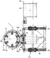
In an embodiment, the base section and the first and second pinches each extend along a 120 degree arc trajectory. Thus, the base section and the first and second pinches may each form one third of the circumference of the pile holding device when the first and second pinches are in the closed position.
In an embodiment, the first and second nips and preferably the base structure each have a semi-circular configuration, such that when the nips are in the closed position the post retaining means has an annular configuration with a circular inner circumference.
In embodiments, the outer ends of the jaws are joined when the first and second jaws are in the closed position, and wherein preferably a locking mechanism is provided to lock the first and second jaws in their closed position, e.g. by connecting the outer ends to each other.
In an embodiment the pile holding device comprises a building envelope, preferably mounted on the base structure, for coarsely positioning the pile and/or preventing collision between the pile and other pile holding device parts.
In an embodiment each pile engaging means comprises a cantilever arm, each cantilever arm having an engaging end and a pivot end, wherein the cantilever arm is pivotably supported at the pivot end such that the cantilever arm is pivotable about a pivot axis, preferably the pivot end being the top end of the cantilever arm and the pivot axis being preferably a horizontal pivot axis, and wherein each cantilever arm is provided with one or more pile engaging elements at the engaging end.
In an embodiment, each pile engaging device comprises a cantilever actuator for positioning the cantilever at different angular positions about the pivot axis so as to allow all pile engaging devices to simultaneously engage corresponding piles having different diameters when the first and second jaws are in their closed position.
The above described embodiments allow for adjustment to accommodate variations in the diameter of the pile being lowered through the pile channel while the pile engaging means engages the outer surface of the pile. The cantilever actuator may be controlled using a diameter adjustment system configured to keep the pile centre fixed and allow the pile engaging element, e.g. a roller, to translate substantially perpendicular to the pile surface. The advantage is that no slipping occurs on the coating of the conical section of the pile.
In an embodiment, the pile engaging device comprises a base frame, wherein the first and second clamps and preferably the base structure each comprise a rail structure, such as a toothed rail or a rail section, extending along the longitudinal direction of the respective first, second clamp or base structure, wherein the base frame of each of the pile engaging devices is movably supported on one of the rail structures, and wherein each base frame has a driver adapted to move the base frame along the rail structure.
In an embodiment, the cantilever actuator is disposed between the base frame and the cantilever.
In an embodiment, the post holding device forms a loop structure when the first and second jaws are in the closed position, and the track structure extends along an inner circumference of the loop structure, preferably along the entire inner circumference.
In an embodiment, the pile holding system further comprises a control system configured to control the drivers of the pile engaging devices and to drive the pile engaging devices in unison along the track structure.
In an embodiment, the one or more pile engaging elements comprise pile guiding rollers, preferably two or more pile guiding rollers supported in a carrier pivotably connected to a support end of a cantilever to pivot about a carrier pivot axis, which cantilever in turn is pivotable about a cantilever pivot axis, wherein the pile guiding rollers each have an axis of rotation, wherein the pile guiding rollers are supported by the carrier such that their axes of rotation extend parallel to the carrier pivot axis, and wherein preferably the carrier pivot axis extends parallel to the cantilever pivot axis.
The advantage of the pile guide roller is that the pile engaging device is able to follow the change in diameter of the pile that is reduced through the pile passage when the pile engaging device is engaged with the outer surface of the pile.
In an embodiment, the track structure is a semi-circular track structure.
The first aspect of the invention also relates to a vessel comprising a pile holding system mounted on a deck of the vessel, e.g. for mounting a pile suitable for supporting an offshore wind turbine, the pile holding system being configured to support the pile in an upright position in close proximity to a pile mounting location of the vessel, the pile holding system comprising:
-a pile holding device comprising a base structure, a first nip and a second nip each extending between an inner end and an outer end, and wherein the first and second nips are pivotally connected at their inner ends to respective pivot portions of the base structure to pivot about a nip pivot axis between a closed position in which the pile holding device defines a pile passage for holding the pile in the pile holding device and an open position in which the pile can be received in or removed from the pile holding device in a transverse direction;
-a plurality of pile engaging devices, wherein the base structure, the first nip and the second nip each support at least one pile engaging device, the engaging devices each comprising one or more pile engaging elements, e.g. the one or more pile engaging elements each comprising one or more pile guiding rollers; and
-a support system mounted on the deck of the vessel, wherein the support system movably supports the pile holding device at the base structure and is configured to move the pile holding device in a first direction between an inboard position and an outboard position,
wherein when in the outboard position the pile retaining device is located outside the vessel's profile to retain the pile in the erected position at the installation location, and wherein when in the inboard position and the first and second nips are in the open position the pile retaining device is located within the vessel's profile.
In an embodiment, the vessel has a longitudinal axis extending between the bow and the stern of the vessel, and wherein the pile holding device moves perpendicular to the longitudinal axis of the vessel when moving in the first direction.
In an embodiment, the pile holding system is arranged at the stern of the vessel so as to hold the pile outside the contour of the vessel when the stern side of the vessel is viewed from above.
In an embodiment, the vessel further comprises a crane for handling piles, wherein the crane is arranged at the stern of the vessel in line with the centre of gravity of the vessel.
In an embodiment, the pile holding system is arranged in close proximity to the crane.
In an embodiment, the vessel further comprises a storage position at the stern of the vessel at the side of the crane opposite to the side where the pile holding system is arranged, the storage position allowing storage of a pile mounting mechanism for driving a pile into the seabed.
In an embodiment, the vessel comprises a deck space for storing piles in a horizontal orientation parallel to the longitudinal axis of the vessel.
The invention also relates to an installation method for supporting a pile of an offshore wind turbine, wherein the method is at least partly performed using a vessel according to the invention, and wherein the method comprises the steps of:
a. transporting the pile to an offshore pile installation location;
b. moving the pile holding device from the inboard position to the outboard position with the first and second nips of the pile holding device in the open position;
c. lifting a pile at its upper end and positioning it in a pile holding device;
d. moving the first and second nips of the pile holding device to their closed positions;
e. lowering the pile to the seabed; and
f. the pile is driven into the seabed.
In embodiments, the method further comprises the steps of: positioning a pile relative to the installation position using the support system of the pile retention system.
In embodiments, during step e, the pile is held by the pile holding device.
In an embodiment, the vessel is in a floating state during at least one or more steps, preferably during all steps.
In an embodiment, during step e and/or step f, the pile holding device compensates for wave induced motion of the vessel in order to maintain a predetermined X-Y position independent of the wave induced motion of the vessel.
In an embodiment, the vessel further carries out step a.
In an embodiment, step c and/or step e is carried out by a crane on said vessel.
In an embodiment, the pile is positioned in the pile holding device such that the pile and the pile holding device move relative to each other until the pile engages with the envelope of the pile holding device.
In an embodiment, the pile engages with the enclosure after positioning the pile in the pile holding device, and wherein the pile engaging device is adapted to engage with the pile only after step d.
It should also be noted that installing an offshore base pile before driving the pile into the seabed also often involves rotating the pile about its longitudinal axis in order to position it correctly on the pile installation site. The features of the stake, such as access doors, mounting holes, power cable manholes, etc., must be properly oriented.
In the prior art, the orientation of the pile is correct when the pile is supported in the pile holding device by a crane, the pile having engaged with the pile engaging device comprising rollers engaging the pile, centering the pile in the pile holding device. Typically, prior art pile holding arrangements have a pile setting machine, which is an additional device mounted on the pile holding arrangement, which can contact the pile to rotate the pile about its longitudinal axis. The pile driver comprises a movably supported driving wheel with a vertical axis of rotation. For orienting the pile, a drive wheel is arranged on the circumferential surface of the pile and drives, thereby rotating the pile about its vertical axis. It is pointed out here that while rotating, the pile also engages with the pile engaging means of the pile holding means, thereby centering the pile in the holding means. Typically, the pile engaging device engages the pile with a roller to contact the pile, the roller being supported such that it has a horizontal axis of rotation. Thus, the rotation axis of the roller extends perpendicular to the longitudinal axis of the pile. Thus, the roller does not roll with the pile and the driving wheel must have a strong power and be pressed hard against the surface to overcome the friction between the pile engaging means and the pile in order to rotate the pile. This makes the process of rotating the pile difficult to manage and inaccurate.
Furthermore, the prior art configuration has the following problems: features provided on the outer surface of the pile, such as mooring lugs or entrances, may collide with the pile engaging means and/or the pile driver during rotation. Thereby preventing proper orientation and/or requiring the pile to be lifted or lowered during orientation.
It is another object of the present invention to provide an alternative pile retention system. Another object of the invention is to provide an improved pile holding device for improving the orientation of the pile. It is a further object of the present invention to provide an improved installation method suitable for supporting a pile of an offshore wind turbine.
According to a second aspect, the present invention provides a pile holding device for installation on a deck of a vessel, for example to install a pile holding system suitable for supporting a pile of an offshore wind turbine, the pile holding system being configured to support the pile in an upright position in close proximity to a pile installation location of the vessel, wherein the pile holding device comprises:
-a base structure, a first and a second nip, each extending between an inner end and an outer end, and wherein the first and second nips are pivotally connected at their inner ends to respective pivot portions of the base structure to pivot about a nip pivot axis between a closed position in which the pile holding device defines a pile channel for holding the pile in the pile holding device, and an open position in which the pile can be received in or removed from the pile holding device in a transverse direction;
a rail structure, such as a rack or a rail section, comprised in the first and second pinches and preferably the base structure, the rail structure extending along a longitudinal direction of the respective first pinches, second pinches or base structure,
-three main pile engaging devices, wherein the main pile engaging devices each comprise a base frame, one or more pile engaging elements, for example each comprising one or more pile guide rollers for engaging the pile in the pile channel, and an actuator for moving the one or more pile engaging elements between an active position and a passive position for engaging and releasing the pile located in the pile holding device, respectively, and allowing all main pile engaging devices to simultaneously engage piles of different diameters when the pile engaging elements are in the active position and the first and second jaws are in their closed position,
wherein the pile column engaging means further comprises a base frame, the base frame of each of the pile column engaging means being movably supported on one of the track structures,
wherein each base frame is provided with a drive for moving the base frame along the rail structure and thereby the pile engaging means, more particularly the pile engaging element, along the inner circumference of the pile holding device while engaging a pile in order to rotate the pile supported by the crane in the pile holding device around its longitudinal axis, and
wherein the pile holding system further comprises a control system configured to control the driver of the pile engaging device and to drive the pile engaging device in unison along the track structure.
It is noted here that the pile holding device may also comprise four or more main pile engagement devices, in which embodiment the control system is configured to drive all main pile engagement devices in unison along the track structure.
In an embodiment the pile holding device according to the claimed invention comprises three main pile engaging devices comprising a base frame movably supported on one of the rail structures provided on the pile holding device. Each base frame is provided with a drive adapted to move the base frame along the rail structure and thereby the pile engaging device, more particularly the pile engaging element, along the inner circumference of the pile holding device while engaging a pile in order to rotate the pile supported by the crane in the pile holding device about its longitudinal axis.
Thus, with the pile holding arrangement according to the second aspect of the invention, no pile erecting machine, i.e. no separate arrangement configured to rotate the pile when supported by the crane, is required. Furthermore, because the pile is rotated by the primary pile engaging means engaging the pile to also center it in the pile holding means, the pile engaging means moves with the pile and, therefore, the pile engaging element contacting the outer surface of the pile also moves with the pile. This enables a more controllable process compared to the prior art, thereby enabling efficient and accurate orientation of the pile.
In an embodiment, the first and second pinches and preferably the base structure each comprise a track structure, such as a rack or rail section, extending along the longitudinal direction of the respective first, second pinches or base structure. Preferably, the post retaining device forms a loop when the first and second jaws are in the closed position.
In an embodiment, the track structure is a semi-circular track structure. The track structures are preferably aligned, i.e. extend along a section of a circle, which extends in a horizontal plane. In such an embodiment, the track structure may be combined into a circular support track structure when the clamping part of the pile holding device is in the closed position.
In an embodiment, the pile holding device forms a loop structure when the first and second jaws are in the closed position, and the track structure extends along the inner circumference of the loop structure, preferably along the entire inner circumference. This allows the pile engaging means to be configured to travel along the entire inner circumference of the pile retaining means and thus allows the pile to be rotated 360 degrees or more without the need for the pile engaging means to disengage from the pile.
In an embodiment, the one or more pile engaging elements of the king pile engaging device comprise pile guide rollers, preferably two or more pile guide rollers supported in a carrier pivotably connected to the support end of a cantilever for pivoting about a carrier pivot axis, which cantilever in turn is pivotable about a cantilever pivot axis, wherein the pile guide rollers each have a rotational axis, wherein the pile guide rollers are supported by the carrier such that their rotational axes extend parallel to the carrier pivot axis, and wherein preferably the carrier pivot axis extends parallel to the cantilever pivot axis.
The advantage of the pile guide roller is that the main pile engagement device can follow the change of the diameter of the pile being lowered through the pile passage while the pile engagement device engages the outer surface of the pile.
In an embodiment the pile holding device further comprises three second pile engaging devices for engaging a pile when the primary pile engaging device is in the passive position, wherein the second pile engaging devices each comprise one or more pile engaging elements and an actuator, e.g. second pile engaging devices each comprise one or more pile guide rollers for engaging the pile in the pile channel, the actuator for moving the one or more pile engaging elements between an active position and a passive position for engaging and releasing the pile located in the pile holding device, respectively, and allowing all second pile engaging devices to simultaneously engage piles of different diameters when the pile engaging elements are in the active position and the first and second jaws are in their closed position.
In such an embodiment, the control system of the pile holding system is configured to control the driver of the primary pile engagement device and to drive the primary pile engagement device in unison along the track structure, and to control the driver of the second pile engagement device to drive the second pile engagement device in unison along the track structure.
The provision of three second pile engaging means allows the second engaging means to engage the pile and maintain the orientation of the pile when the primary pile engaging means releases the pile. Thus, after having been moved in one direction along the track structure to rotate the pile, the king pile engaging means may be moved in the opposite direction along the track structure, re-engaging the pile and rotating the pile further. In such an embodiment, the track structure does not need to form a continuous track around the inner circumference of the pile holding device to rotate the pile 360 degrees. By repeatedly rotating the post within a limited interval, the post may still be rotated 360 degrees or more.
In an embodiment, the second pile engaging device further comprises a base frame, the base frame of each of the second pile engaging devices being movably supported on one of the rail structures, and
wherein each base frame is provided with a drive adapted to move the base frame along the rail structure and thereby the pile engaging means, more particularly the pile engaging element, along the inner circumference of the pile holding means while engaging a pile in order to rotate the pile supported by the crane in the pile holding means around its longitudinal axis.
Thus, the pile may be rotated by the primary pile engagement means and the secondary pile engagement means. Preferably, the second pile engaging means are interposed between the primary pile engaging means such that the primary engaging means alternate with the second engaging means along the circumference of the pile holding means. This is beneficial, for example, when a surface feature of the pile is aligned with one of the primary pile engagement means, which may hinder the pile engagement means from engaging with the pile. In this case, a second pile engaging device may be used instead of the main pile engaging device for engaging the pile and rotating it by the first angle. Once the pile has been rotated by the second pile engaging means, the surface features have moved sufficiently for the primary pile engaging means to engage the pile and rotate the pile through a second angle.
In an embodiment, each track structure supports at least one primary pile engaging means and at least one secondary pile engaging means. In an alternative embodiment, each track structure supports either a primary pile engaging device or a secondary pile engaging device.
In embodiments, one or more rail structures are connected to each other, thereby allowing the pile engaging device to be moved from one rail structure to another connected rail structure. This may also allow one or more pile engaging devices to be temporarily moved to a single track structure, for example when the pile holding device is supported in an inboard storage position.
In an embodiment, the track structure is formed by an annular track extending along the entire inner circumference of the pile holding device, the annular track supporting the primary pile engaging device, and preferably the secondary pile engaging device.
In an embodiment, the track structure is formed by a first and a second annular track, both extending along the entire inner circumference of the pile holding device.
In an embodiment the primary pile engagement device and preferably the second pile engagement device each comprise a cantilever arm, each cantilever arm having an engagement end and a pivot end, wherein the cantilever arm is pivotably supported at the pivot end such that the cantilever arm is pivotable about a pivot axis, preferably the pivot end being the top end of the cantilever arm and the pivot axis being preferably a horizontal pivot axis, and wherein each cantilever arm is provided with one or more pile engagement elements at the engagement end.
In an embodiment, each pile engaging device comprises a cantilever actuator for positioning the cantilever at different angular positions about the pivot axis so as to allow all pile engaging devices to simultaneously engage corresponding piles having different diameters when the first and second jaws are in their closed position.
In another embodiment, the cantilever actuator is disposed between the base frame and the cantilever.
The above described embodiments allow adjustment for variations in the diameter of the pile being lowered through the pile passage while the pile engaging means engages the outer surface of the pile. The cantilever actuator may be controlled using a diameter adjustment system configured to keep the pile centre fixed and to allow the pile engaging element, e.g. a roller, to translate substantially perpendicular to the pile surface. The advantage is that no sliding occurs on the coating of the conical section of the pile.
In an embodiment, the post holding device forms a loop structure when the first and second jaws are in the closed position, and the track structure extends along an inner circumference of the loop structure, preferably along the entire inner circumference.
In an embodiment, the one or more pile engaging elements comprise pile guide rollers, preferably two or more pile guide rollers supported in a carrier pivotably connected to the support end of a cantilever to pivot about a carrier pivot axis, which cantilever in turn is pivotable about a cantilever pivot axis, wherein the pile guide rollers each have an axis of rotation, wherein the pile guide rollers are supported by the carrier such that their axes of rotation extend parallel to the carrier pivot axis, and wherein preferably the carrier pivot axis extends parallel to the cantilever pivot axis.
The advantage of the pile guide roller is that the pile engaging device can follow the change of the diameter of the pile being lowered through the pile passage while the pile engaging device is engaged with the outer surface of the pile.
In an embodiment, the base structure, the first and second clamps each support at least one pile engaging device.
According to a second aspect, the present invention also provides a pile retention system for installation on a deck of a vessel, for example for installation of a pile suitable for supporting an offshore wind turbine, the pile retention system being configured to support the pile in an upright position in close proximity to a pile installation location of the vessel, the pile retention system comprising:
a pile holding device according to the second aspect of the invention, and
-a pile holding device support system mounted on the deck of the vessel, wherein the support system supports the pile holding device at the base structure, preferably movably supporting the pile holding device at the base structure.
In an embodiment, the pile retention device support system is configured to move the pile retention device between an inboard position and an outboard position, preferably in a first direction, which is substantially parallel to a deck of a vessel when the pile retention system is mounted on the deck of the vessel.
In an embodiment, the pile holding device is located outside the outline of the vessel when in the outboard position to hold the pile in the upright position at the installation position, and wherein the pile holding device is located within the outline of the vessel when in the inboard position with the first and second nips in the open position.
According to a second aspect, the present invention also provides a method for rotating a pile driven into the seabed at a pile installation site, the method comprising the steps of;
-positioning a vessel provided with a pile holding device according to the second aspect of the invention near the pile installation location and supporting the pile holding device in an outboard position to engage the pile;
-supporting the pile in a vertical position in the pile holding device using a crane;
-engaging the pile with the main pile engagement device supported on the track structure provided on the pile holding device; and
-moving the main pile engagement device in a forward direction along the track structure and thereby rotating the pile about its longitudinal axis.
The invention also relates to a pile holding device according to the second aspect, comprising:
a base structure, e.g. adapted to be mounted, e.g. pivotably mounted, to a support frame as described herein, to pivot relative to the support frame about a base pivot axis between a substantially vertical orientation and a substantially horizontal orientation,
-a ring structure configured to extend around a passage for a pile to be handled by the pile holding device, the ring structure being supported by a base frame or the base frame structure forming a section of the ring structure,
wherein the ring-shaped structure comprises two semi-circular clamping portions, each clamping portion being pivotally connected at an inner end thereof and each clamping portion being pivotable about a pivot axis between a closed position in which the outer ends of the clamping portions are joined together,
wherein the ring-shaped structure is provided with a circular support track structure carrying a plurality of pile engaging devices, e.g. with pile guide rollers, e.g. four or more pile guide rollers, here six such devices,
wherein preferably one or more, e.g. all, of the pile engaging means are movable along the circular support track structure, at least through one arc of a circle, thereby allowing the angular position of the pile engaging means relative to the passage of the pile to be adapted.
Thus, the pile holding device may comprise an annular structure defined by two semi-circular nips with pile engaging means, such as the main pile engaging means.
In an embodiment, each pile engaging device is movably loaded with one or more pile guide rollers, e.g. a pair of two pile guide rollers, to allow adjustment of the radial position of the rollers relative to the passage for the pile. For example, each pile engaging means comprises a cantilever arm pivotable about a horizontal axis relative to a base frame of the device supported on the rail structure, where the pivoting preferably starts from the top end of the arm.
In embodiments, a cantilever actuator, e.g., a hydraulic actuating cylinder, is provided between the base frame and the arm for adjusting the radial position of the one or more rollers.
In an embodiment, here each base frame is provided with a motorized drive for moving the base frame along the circular rail structure, possibly along a section of the circular rail structure, in order to adjust the angular position of the device.
Another method comprises the steps of:
-engaging a pile with a second pile engagement device and releasing the pile from the primary engagement device after rotating the pile by a first angle; and
-moving the king pile engaging means in a rearward direction along the track structure;
-engaging the pile with the primary pile engagement means and releasing the pile from the second pile engagement means; and
-moving the main pile engagement device in a forward direction along the track structure and thereby rotating the pile about its longitudinal axis.
An alternative method comprises the steps of:
-after rotating the pile by a first angle, engaging the pile with a second pile engagement device and releasing the pile from the primary engagement device; and
-moving the second pile engaging device in a forward direction along the track structure and thereby rotating the pile about its longitudinal axis;
-moving the king pile engaging means in a rearward direction along the track structure;
-engaging the pile with the primary pile engagement means and releasing the pile from the second pile engagement means; and
-moving the main pile engagement device in a forward direction along the track structure and thereby rotating the pile about its longitudinal axis.
It will be appreciated that the benefits of the pile retention device according to the second aspect of the invention may be combined with the pile retention system according to the first aspect of the invention as well as with the pile retention system according to the other aspects of the invention. Likewise, all embodiments of the pile holding device according to the second aspect of the invention and each of the other technical features discussed with reference to the other aspects of the invention may be combined with the pile holding device according to the invention, e.g. in various combinations of such features.
Thus, for example, the pile holding device according to the second aspect of the invention may be combined with the pile holding system according to the fourth aspect of the invention, i.e. with a pile holding system comprising a vertical support frame extending between a lower end of the vertical support frame and an upper end of the vertical support frame. Wherein the vertical support frame is configured to move in a vertical direction relative to the mounting frame between a lowered position and a raised position and is fixed to the mounting frame in the lowered position and in the raised position, and wherein the vertical support frame supports the pile retaining device near a lower end thereof.
The invention also relates to a pile holding device according to the second aspect, comprising a base structure, e.g. adapted to be mounted, e.g. pivotably mounted, to a support frame as described herein, for pivoting relative to the support frame about a base pivot axis between a substantially vertical orientation and a substantially horizontal orientation.
According to a third aspect of the present invention there is provided a pile holding system for installation on a deck of a vessel, for example for installing a pile suitable for supporting an offshore wind turbine, the pile holding system being configured to support the pile in an upright position in close proximity to a pile installation location of the vessel, the pile holding system comprising:
-a pile holding device comprising a base structure, a first nip and a second nip each extending between an inner end and an outer end, and wherein the first and second nips are pivotally connected at their inner ends to respective pivot portions of the base structure to pivot about a nip pivot axis between a closed position in which the pile holding device defines a pile passage for holding a pile in the pile holding device and an open position in which the pile can be received in or removed from the pile holding device in a transverse direction;
-a plurality of pile engaging devices, wherein the base structure, the first nip and the second nip each support at least one pile engaging device, the engaging devices each comprising one or more pile engaging elements, e.g. the engaging devices each comprising one or more pile guiding rollers for engaging the pile in the pile channel; and
-a pile holding device support system mounted on a deck of the vessel, wherein the support system movably supports the pile holding device and is configured to move the pile holding device in a first direction between an inboard position and an outboard position,
wherein when in the outboard position the pile retaining device is located outside the contour of the vessel to retain the pile in the upright position at the installation location, and wherein when in the inboard position the pile retaining device is located within the contour of the vessel.
In an embodiment, the pile holder support system is configured to move the pile holder to an extraction position in which the pile holder is located within the outline of the vessel and above an accessory storage area of the vessel, such that accessories stored in the accessory storage area, such as a vertical foldable noise reduction screen, can be attached to the pile holder, preferably to the base structure, the first and second pinches of the pile holder.
Thus, the pile holder support system is configured such that the pile holder can be positioned above an accessory on the vessel, e.g. above an accessory on the deck of the vessel. This facilitates mounting of the accessory to the pile holding device, especially when full tide, without the need for a second vessel to position the accessory below the pile holding device.
By the pile holding system according to the invention both the accessory and the pile holding device are located on the same vessel, so that there is no relative movement between the accessory and the pile holding device, which is extremely advantageous for the installation and removal of said accessory.
For example, such embodiments allow for positioning the stake holding devices above the upright foldable noise reduction screen that is stored on the boat. During storage, the accessories may be inspected, repaired, etc. if necessary. Once the use of the accessory is required, the pile holding device is moved over the accessory, which can be attached to the pile holding device, which is then hoisted overboard by the pile holding device. Thus, there is no need for e.g. a second vessel to position the accessory below the pile holding device, nor is there a need for one or more cranes to lift the accessory from the second vessel so that it can be mounted to the pile holding device.
In an embodiment, the pile holding device is provided with a dedicated support, such as a bracket or support frame, for mounting accessories. In another embodiment the pile holding device is provided with guides, such as brackets or racking, for lifting wires for positioning accessories in the vicinity of the pile holding device and/or for supporting pile accessories during use of the pile holding device.
In an embodiment the pile holding device has one or more winches on and/or leading wires from those winches via the pile holding device for lifting accessories from the accessory storage area, e.g. from the deck of the vessel, towards the pile holding device, so that the accessories can be mounted on the pile holding device and/or supported during use of the pile holding device.
In an embodiment, the pile retention device support system comprises: a base rail extending in the first direction; a base track bracket supporting the pile retaining device; and a base track carriage driver for moving the base track carriage along the base track.
The base rail is mounted on the deck of the vessel and allows the pile holding device to move from an inboard position within the outline of the vessel to an outboard position outside the outline of the vessel. The monorail construction allows for simple and clean installation on a ship, especially when the base rails comprise a single beam structure to be installed on the deck of the ship. In such an embodiment, the extraction location is located on one side of the base track. Preferably the single beam structure supports the pile holder at a height above the deck of the vessel, thereby allowing storage of accessories on the deck of the vessel, the deck below the storage position of the pile holder being the accessory storage position.
In another embodiment, the pile holding devices may be positioned on opposite sides of the single rail above the deck of the vessel and/or above an accessory storage area. Thus, for example, the deck at one side of the base rail may be used for storing accessories in use, while the deck at the other side of the base rail may be used for inspection and maintenance of the pile holding device.
In an alternative embodiment, the support system comprises: a first base rail and a second base rail extending in the first direction; a first base track bracket and a second base track bracket, the base track bracket supporting the pile retaining device; and a first base track carriage driver and a second base track carriage driver for moving the base track carriage along the first and second base tracks, respectively. This embodiment still allows for a smaller footprint, especially when each base rail comprises a single beam structure to be mounted on the deck of the vessel and combined with a more robust support. Preferably, the extraction position is located between the first and second base rails, allowing the pile holding device to be supported on both sides when the accessory is installed.
It is noted that the present invention provides a pile holding system, the pile holding device of which may be mounted on the deck of a vessel and which may be positioned above the deck of said vessel. The deck of the vessel not only facilitates the installation and removal of accessories at full tide, but also facilitates access to the pile holding means, e.g. for inspection, maintenance etc. Furthermore, it allows the accessory to be lifted from an inboard position to an outboard position using the pile retaining device. This reduces the need for the crane to be used, so that the crane can be used for other activities.
In an embodiment, the pile holding device support system is configured to move the pile holding device in a second direction, preferably perpendicular to the first direction, and the pile holding system further comprises a motion control system configured to move the pile holding device in the first direction and in the second direction relative to the vessel when in the outboard active position, so as to push and/or hold the pile in the upright position at the installation position as the pile is lowered towards the seabed and/or after the pile is landed on the seabed.
Thus, the pile holding device support system serves to guide the pile, but also to actively hold the pile in an upright position as it is lowered towards the seabed and/or as it is driven into the seabed. Movement of the pile holding device relative to the vessel allows the pile holding device to compensate for drift of the vessel relative to the pile mounting position.
Furthermore, especially when the pile is lowered towards the seabed, the movement of the pile holding device relative to the vessel may be used to compensate for deviations of the pile relative to the upright position, e.g. caused by the position of the crane supporting the pile when lowered towards the seabed, the sea currents, the composition of the top layer of the seabed on which the pile is lowered, etc.
In an embodiment, the motion control system is configured to hold the pile holding device in a predetermined gps position, e.g. a position on the seabed where a pile in an upright position, guided by the pile holding device, falls.
In an embodiment of the pile holding system according to the invention, the support system comprises a second rail extending in the second direction and perpendicular to the base rail or to the first and second base rails. In another embodiment, the second rail base comprises a single beam structure supported by the base rail bracket or the first and second base rail brackets.
Thus, the pile support system comprises rails each arranged in a T-shape or H-shape, the second rail being movable relative to one or more base rails mounted on the deck. This provides a robust pile support system which occupies a small area and can also be installed on the deck of the vessel without requiring significant redesign of the vessel or requiring significant deck space.
The invention also provides a pile holding system comprising a motion control system, the motion control system comprising a pile monitoring system, for example comprising a camera and or a laser, the pile monitoring system being configured to monitor the orientation of the pile held by the pile holding device in a pile channel, the pile monitoring system being connected to the motion control system.
Providing the pile holding system with a motion control system configured to move the pile holding device while taking into account such data may make the installation more accurate. Preferably, the motion control system is configured to use said information to actively control the pile holding device as the pile is lowered towards the seabed and/or as the pile is driven into the seabed.
The invention also provides a pile holding system, the motion control system of which is configured to be linked to a crane monitoring system of a crane for handling and/or lowering the pile towards the seabed, the crane monitoring system providing information about the orientation and/or speed of a hoisting device of a crane supporting the pile at the top end of the pile.
Providing the pile holding system with a motion control system configured to move the pile holding device while taking into account such data may make the installation more accurate. Preferably, the motion control system is configured to use said information to actively control the pile holding device as the pile is lowered towards the seabed and/or as the pile is driven into the seabed.
In another embodiment the motion control system is configured to control the hoisting device of the crane to move and/or hold the pile or at least its top end to/in a specific position relative to the pile holding device, preferably while lowering the pile towards the seabed using the crane.
The invention also provides a pile holding system whose motion control system comprises or is configured to be linked to a vessel monitoring system that provides information about the position and/or orientation and/or speed of the vessel supporting the pile holding system.
Providing the pile holding system with a motion control system configured to move the pile holding device while taking such data into account may make the installation more accurate. Preferably, the motion control system is configured to use said information to actively control the pile holding device as the pile is lowered towards the seabed and/or as the pile is driven into the seabed.
In another embodiment the motion control system is configured to control the propulsion of the vessel to move the pile holding device to and/or hold the pile holding device in a specific position. Thus, the motion control system is not limited to moving the pile holder within the moving window provided by the pile holder support system.
The invention also provides a pile holding system whose motion control system comprises or is configured to be linked to a wave monitoring system which monitors incoming waves, for example using radar, so that the motion control system can use this information to move the pile holding device to a specific position and/or to hold the pile holding device in a specific position.
Providing the pile holding system with a motion control system configured to move the pile holding device while taking such data into account may make the installation more accurate. Preferably the motion control system is configured to use said information to actively control the pile holding device as the pile is lowered towards the seabed and/or as the pile is driven into the seabed.
In embodiments, the first and second jaws are configured to move between a closed position in which the first and second jaws are in a closed position and an open position in which the first and second jaws are in an open position, and a closed position in which the first and second jaws are in an open position. Such an embodiment allows for positioning the pile holding device within the contour of the vessel along and close to the contour of the vessel.
Additionally, or alternatively, the pile holder support system is configured to move the pile holder into an inboard position, i.e. within the contour of the vessel, with the nip in the closed position. This may be the preferred location of the nip when mounting an accessory to the post holder.
In an embodiment, the pile retention system further comprises an actuation system configured to pivot the first clamp between its closed and open positions and configured to pivot the second clamp between its closed and open positions.
In an embodiment, in the inboard position, substantially the entire pile retention system is located within the contour of the vessel. An advantage of being able to open and fully retract the pile holding device is that large objects, such as pile mounting hammers or transition pieces, can easily pass through the pile holding system. This also allows positioning and/or erecting the pile near the vessel without risk of the pile touching the pile holding device, possibly damaging the pile holding device or accessories supported by the pile holding device.
In an embodiment, the pile is handled by a crane near the vessel, the crane being mounted on the vessel supporting the pile holding system. The pile holding device can only be moved from its position inside the ship's contour to a position outside the ship's contour for receiving a pile when the crane supports the pile in an upright position.
In an embodiment, the clamp of the vessel is opened to engage the pile in a lateral direction. Alternatively, the nip is closed and the pile is lowered by the crane into a pile channel defined by the nip.
In an embodiment, the pile holding device in the outboard position and the inboard position has a horizontal orientation, and wherein the support system is configured to move the pile holding device between the inboard position and the outboard position while maintaining the horizontal orientation of the pile holding device.
In embodiments, the first direction is a substantially horizontal direction. The pile holding device can be held in the same orientation during its movement between the inboard and outboard positions, which means that the pile holding device does not pivot up or down nor tilt.
In an embodiment, the base structure of the pile holding device is pivotably mounted to the support system such that the pile holding device is pivotable relative to the support system about a base structure pivot axis between a substantially vertical orientation and a substantially horizontal orientation. In this example it is envisaged that this tilting only takes into account sailing with the vessel, mooring in port etc., but it is also envisaged that the pile is hoisted and placed in a vertical orientation with a crane before the pile holding device is engaged with the pile.
As mentioned above, in embodiments the support system is configured to move the pile holding device in a second direction between a first outer position and a second outer position to allow the support system to position the pile holding device in a horizontal plane relative to the vessel, the second direction preferably being perpendicular to the first direction.
In an embodiment, the support system comprises: a base rail, preferably a base rail to be mounted on a deck of the vessel, extending in the first direction; and a base carriage for movement along the track, wherein the base carriage is configured to support the base structure of the pile holding device, and wherein the base structure is movable between a first outer position and a second outer position, preferably in a second direction perpendicular to the first direction, to allow the support system to position the pile holding device relative to the vessel in a horizontal plane.
Alternatively, the base track may extend in the second direction and the base structure of the pile holding device may be movable in the first direction relative to the base carriage. In such an embodiment, the base carriage supports a second rail along which the pile holding device is movable.
In an embodiment, the base bracket comprises a U-shaped bracket frame, the bracket frame comprising: two legs, each leg extending along a track, preferably each leg extending along a rail of the track; and at least one transverse connecting portion connecting the legs of the frame. The at least one transverse connecting portion preferably connects the ends of the legs facing the pile holding device, and the at least one transverse connecting portion preferably supports the base structure.
In an embodiment, the base carrier comprises an I-shaped or T-shaped carrier frame comprising a portion corresponding to an I-shaped or T-shaped vertical bar, wherein said portion extends along a track, and wherein a further track is provided at a free end of the I-shaped carrier frame or a portion of the carrier frame corresponding to a horizontal bar of the T-shape, and wherein the base structure is movably connected to the further track.
In an embodiment, the pile support system further comprises a motion control system configured to provide active motion compensation in the horizontal plane to compensate for movement of the vessel relative to the pile installation location when the pile holding device supports the pile in the upright position proximate to the installation location of the vessel.
In an embodiment, the pile support system further comprises: a monitoring system configured to monitor the position and/or orientation of the pile when the pile is loaded into the pile holding device and/or when the pile holding device supports the pile in the upright position proximate to the pile installation location of the vessel; and a control system configured to control movement of the first and second nips with the support system.
In an embodiment, the control system is configured to move the pile away from the vessel, for example by moving the pile holding device towards and/or beyond the outboard position, when the monitoring system indicates that the position and/or orientation of the pile exceeds a predetermined first value.
In an embodiment, the control system is configured to automatically move the first and second nips into their respective open positions to avoid interference between the pile on the one hand and the first and second nips on the other hand.
In other words, the control system may be configured to push the pile away from the vessel by: -moving the pile holding device towards and/or beyond the outboard position when the clamping portion of the pile holding device is in the open position, and/or-automatically opening the clamping portion of the pile holding device and moving the pile holding device towards and/or beyond the outboard position when the position and/or orientation of the pile exceeds a predetermined value.
In such an embodiment, the support system is preferably configured to move the pile holding device beyond the outboard position, particularly when the pile has not been driven into the seabed. Preferably the control system is configured to cover information about the installation of the pile, more particularly to be able to monitor, for example using the monitoring system, whether the pile has been driven into the seabed, and preferably only to allow the pile to be pushed off the vessel when the pile has not been installed in the seabed, and/or to be no longer supported by a crane, and/or to remove the connection between the pile and the crane supporting the pile.
In an embodiment, the control system is configured to move the pile holding device away from the pile by moving the pile holding device towards the inboard position when the monitoring system indicates that the position and/or orientation of the pile exceeds a predetermined second value. The first and second values may be the same. This embodiment is particularly useful when the pile has been driven at least partially into the seabed and it is no longer possible, not possible or desirable to push the pile aside.
The monitoring system may also be configured to monitor whether the pile has been at least partially driven into the seabed, such that the control system initiates the above-described embodiment, i.e. function, when the pile is at least partially driven into the seabed. Of course, it is also possible to manually activate this function.
In an embodiment, the base section and the first and second pinches each extend along a 120 degree arc trajectory. Thus, the base section and the first and second pinches may each form one third of the circumference of the pile retention device when the first and second pinches are in the closed position.
In an embodiment, the first and second nips and preferably the base structure each have a semi-circular configuration, such that when the nips are in the closed position the post retaining means has an annular configuration with a circular inner circumference.
In embodiments, the outer ends of the jaws are joined when the first and second jaws are in the closed position, and wherein preferably a locking mechanism is provided to lock the first and second jaws in their closed position, e.g. by connecting the outer ends to each other.
In an embodiment, the pile holder comprises a building envelope, preferably mounted on the base structure, for coarsely positioning the pile and/or preventing collision between the pile and other pile holder parts.
In an embodiment, each pile engaging device comprises a cantilever arm, each cantilever arm having an engaging end and a pivot end, wherein the pivotable cantilever arm is pivotably supported at the pivot end such that the cantilever arm is pivotable about a pivot axis, preferably the pivot end being the top end of the cantilever arm and the pivot axis preferably being a horizontal pivot axis, and wherein the engaging end of each cantilever arm has one or more pile engaging elements.
In an embodiment, each pile engaging device comprises a cantilever actuator, preferably a hydraulic actuating cylinder, for positioning the cantilever at different angular positions about the pivot axis to allow all pile engaging devices to simultaneously engage corresponding piles having different diameters when the first and second jaws are in their closed position.
The above described embodiments allow for adjustment of the change in diameter of the pile being reduced through the pile channel when the pile engaging means engages the outer surface of the pile. The cantilever actuator may be controlled using a diameter adjustment system configured to keep the pile centre fixed relative to the pile holding device and to allow the pile engaging element, e.g. a roller, to translate substantially perpendicular to the pile surface. The advantage is that no sliding occurs on the coating of the conical section of the pile.
In an alternative embodiment the pile engaging device comprises cantilevers extending in radial direction with respect to the pile channel, each cantilever having a base end at the nip or the base structure of the nip located radially outwards and an engaging end radially inwards, wherein the cantilever is provided with one or more pile engaging elements at the engaging end.
Such a radial cantilever may comprise an axial actuator, e.g. a hydraulically actuated cylinder or a spindle, for moving the engagement end in a radial direction, i.e. towards the pile and thereby pushing the pile engaging element against the pile, and for moving the engagement end away from the pile supported in the pile channel and thereby out of engagement with the pile, e.g. allowing a bracket or port, e.g. provided on or in the pile surface, to pass the pile engaging element.
In an embodiment the pile engaging device comprises a base frame, wherein the first and second grippers and preferably the base structure each comprise a track structure, such as a toothed rail or a rail section, extending in the longitudinal direction of the respective first, second gripper or base structure, wherein the base frame of each of the pile engaging devices is movably supported on one of the track structures, and wherein each base frame has a driver for moving the base frame along the track structure and thus the pivotable cantilever or the radial cantilever supported on the base frame along the track structure.
In embodiments, the cantilever actuator is disposed between the base frame and the pivotable cantilever.
In an embodiment each pile engaging means is provided with its own hydraulic power source for powering a cantilever actuator for moving the engaging end of the cantilever relative to the base frame towards and away from the pile and/or a driver for moving the base frame along the track structure. The hydraulic power source is preferably located on the base frame. Alternatively, the hydraulic power source is located on the base structure or nip supporting a particular pile engaging means.
In an embodiment, the pile holding device forms a loop structure when the first and second jaws are in the closed position, and the track structure extends along an inner circumference of the loop structure. In another embodiment the combined track structure extends along the entire inner circumference of the pile holding device.
In an embodiment, the pile holding system further comprises a control system configured to control the driver of the pile engaging device or series of pile engaging devices and configured to drive the pile engaging devices in unison along the track structure. In another embodiment the pile engaging device is configured to be driven along the track structure when engaging a pile in the pile channel to rotate the pile about the longitudinal axis of the pile.
Thus, in such embodiments, the pile engagement device may be used to locate and guide the pile as it is lowered towards and/or driven into the seabed, and to rotate the pile about its longitudinal axis. Typically, in prior art mono pile grippers, one or more dedicated pile rotating devices are provided. The use of these special devices requires disengagement from the pile engaging device or otherwise the pile is fixed in position. In the embodiments according to the invention discussed above, there is no separate pile rotation device, so the pile engagement device can remain in contact with the pile when the pile is to be rotated.
In another embodiment the pile holding system comprises at least four, preferably at least six pile engaging devices, and wherein the control system is configured to rotate the pile around its longitudinal axis by a first angle using a first set of pile engaging devices, and subsequently rotate the pile around its longitudinal axis by a second angle using a second set of pile engaging devices, each belonging to a single set of pile engaging devices.
In an embodiment the one or more pile engaging elements comprise pile guiding rollers, preferably two or more pile guiding rollers supported in a roller carrier, the roller carrier being pivotably connected to a support end of a cantilever arm, the cantilever arm being a pivotally or axially movable cantilever arm to pivot about a carrier pivot axis. In an embodiment, the pile guide rollers each have an axis of rotation, wherein the pile guide rollers are supported by the roller carrier such that their axes of rotation extend parallel to the roller carrier pivot axis.
In an embodiment, the boom is a pivotally supported boom, the boom is pivotable about a boom pivot axis, and the roll carrier pivot axis extends parallel to the boom pivot axis.
The pile guide roller has the advantage that when the pile engaging means engages the outer surface of the pile, the pile engaging means is able to engage the pile with the plurality of rollers and follow the change in diameter of the pile which decreases through the pile passage.
In an embodiment, the track structure is a semi-circular track structure.
A third aspect of the invention also provides a vessel comprising a pile retention system according to the invention mounted on a deck of the vessel, for example for mounting a pile suitable for supporting an offshore wind turbine, the pile retention system being configured to support the pile in an upright position in close proximity to a pile mounting location of the vessel.
In an embodiment, the vessel comprises a pile holding system mounted on a deck of the vessel, e.g. for mounting a pile adapted for supporting an offshore wind turbine, the pile holding system being configured to support the pile in an upright position in close proximity to a pile mounting position of the vessel, the pile holding system comprising:
-a pile holding device comprising a base structure, a first nip and a second nip each extending between an inner end and an outer end, and wherein the first and second nips are pivotally connected at their inner ends to respective pivot portions of the base structure to pivot about a nip pivot axis between a closed position in which the pile holding device defines a pile channel for holding the pile in the pile holding device and an open position in which the pile can be received in or removed from the pile holding device in a transverse direction;
-a plurality of pile engaging devices, wherein the base structure, the first nip and the second nip each support at least one pile engaging device, the engaging devices each comprising one or more pile engaging elements, e.g. the one or more pile engaging elements each comprising one or more pile guide rollers; and
-a support system mounted on the deck of the vessel, wherein the support system movably supports the pile holding device at the base structure and is configured to move the pile holding device in a first direction between an inboard position and an outboard position,
wherein when in the outboard position the pile retaining device is located outside the vessel's profile to retain the pile in the erected position at the installation location, and wherein when in the inboard position and the first and second nips are in the closed position the pile retaining device is located within the vessel's profile.
In an embodiment, the vessel has a longitudinal axis extending between the bow and the stern of the vessel, and wherein the pile holding device moves perpendicular to the longitudinal axis of the vessel when moving in the first direction.
In an embodiment, the pile holding system is arranged on one side of the vessel in order to hold the pile outside the contour of the vessel when the port or starboard side of the vessel is viewed from above.
In an alternative embodiment, the pile holding system is arranged at the stern of the vessel in order to hold the pile outside the contour of the vessel when the stern side of the vessel is viewed from above.
In an embodiment, the vessel further comprises a crane for handling piles, wherein the crane is preferably arranged near the stern of the vessel, in line with the centre of gravity of the vessel.
In an embodiment, the pile holding system is arranged near the crane.
In an embodiment, the vessel further comprises a deck providing a storage position allowing storage of the pile mounting structure and/or one or more piles used to drive the pile into the seabed and/or the pile retention device accessories in the accessory storage area.
In an embodiment, the vessel further comprises a storage position at the stern of the vessel at the side of the crane opposite to the side where the pile holding system is arranged, the storage position allowing storage of a pile mounting mechanism for driving a pile into the seabed.
In an embodiment, the vessel comprises a deck space for storing piles in a horizontal orientation parallel to the longitudinal axis of the vessel.
In an embodiment the vessel comprises an extraction position for the pile holding device and when in the extraction position the entire pile holding system is located within the vessel's profile, preferably the first and second clamps are also in the closed position.
In an embodiment of the vessel, the pile holding device in the outboard position and in the inboard position has a horizontal orientation, and the support system is configured to move the pile holding device between the inboard position and the outboard position while maintaining the horizontal orientation of the pile holding device.
In another embodiment, the first direction is a substantially horizontal direction, more specifically a direction substantially parallel to a deck surface of the vessel.
In an embodiment, the pile holder support system comprises a motion control system configured to move a pipe holder in a first direction and a second direction relative to the vessel so as to provide active motion compensation in the horizontal plane to compensate for movement of the vessel relative to the pile installation location when the pile holder supports the pile in the upright position proximate to the installation location of the vessel.
In another embodiment, the motion control system comprises: a monitoring system configured to monitor the orientation of the pile while the pile holding device supports the pile in close proximity to the pile installation location of the vessel; and a control system configured to control movement of the first and second nips and the support system.
The invention also relates to an installation method for supporting a pile of an offshore wind turbine, wherein the method is at least partly performed using a vessel according to the invention, and wherein the method comprises the steps of:
a) Transporting the pile to an offshore pile installation location;
b) Moving the pile holding device from the inboard position to the outboard position with the first and second nips in the open position;
c) Lifting a pile at its upper end and positioning it in the pile holding device;
d) Lowering the pile to the seabed; and
e) The pile is driven into the seabed.
In another method according to the invention, step b further comprises moving the pile holding device from an extraction position to the outboard position, preferably after mounting an accessory stored in an accessory storage area below the extraction position onto the pile holding device, and deploying the accessory during step d and/or step e.
In another method according to the invention, step d and/or step e comprises moving the pile holding device in relation to the vessel in a first direction and in a second direction, respectively, using a motion control system, in order to push and/or hold the pile in the upright position at the installation position when the pile is lowered towards the seabed and/or when the pile or at least the first section of the pile is driven into the seabed.
In another method according to the invention, step d and/or step e further comprises using a pile monitoring system, for example comprising a camera and or a laser, for monitoring the orientation of the pile held by the pile holding device in the pile channel, the pile monitoring system being linked to the motion control system.
In another method according to the invention step d and/or step e further comprises using a crane monitoring system for providing information to the motion control system about the orientation and/or speed of the hoisting means of a crane supported at the top end of the pile. Another method comprises using the motion control system for controlling a hoisting device of the crane relative to the pile holding device to move and/or hold the pile or at least its top end to and/or in a specific position.
In another method according to the invention, step d and/or step e further comprises using a vessel monitoring system to provide information to the motion control system about the position and/or orientation and/or speed of the vessel, and preferably using the motion control system to control the propulsion of the vessel to move and/or hold the pile holding device in a specific position.
In another method according to the invention, step d and/or step e further comprises using a wave monitoring system, which monitors incoming waves, e.g. using radar, in order to provide incoming wave information to the motion control system and preferably use this information to move and/or hold the pile holding device in a specific position.
In another method according to the invention, the vessel is in a floating state during at least one or more steps, preferably during all steps. In another method according to the invention, during step e and/or step f, the pile holding device compensates for wave induced motion of the vessel in order to maintain a predetermined X-Y position independent of the wave induced motion of the vessel.
In another method, the vessel further performs step a.
When in a floating state, the vessel is not supported by jack-up legs and is preferably not moored at a dock or sea bed. Preferably the vessel is provided with a control system which operates the vessel's drive, typically a propeller, to hold the vessel in a particular orientation at a particular GPS location. It is noted here that ships with such control systems are known in the prior art. However, pile holding devices are often mounted on jack-up vessels, since it is easier to support the pile from a fixed vessel, i.e. from a vessel supported by jack-up legs.
In embodiments, the method further comprises the steps of: positioning the pile relative to the installation position using the support system of the pile holding system in order to adjust the position of the pile relative to the vessel and optionally relative to a fixed environment (i.e. the seabed) while a crane supports the pile, the crane preferably being installed on the vessel provided with the pile holding system.
In an embodiment, during step d and or step e, the pile is held by the pile holding device.
In an embodiment, step c and/or step e is performed by a crane on said vessel.
In an embodiment, during step d and/or step e, the pile holding device compensates for wave induced motion of the vessel in order to maintain a predetermined X-Y position independent of the wave induced motion of the vessel.
In an embodiment, the vessel further performs step a.
In an embodiment positioning of the pile supported by a crane in the pile holding device is performed such that the pile and the pile holding device are moved relative to each other until the pile engages with a building envelope of the pile holding device, which is preferably mounted on the base structure of the pile holding device. Additionally or alternatively, the vessel is provided with a containment structure configured to prevent a pile supported by the crane from striking the pile holding device and/or the vessel, the containment structure preferably being configured to position a pile supported by the crane in a position usable by the pile holding device for engagement with the pile holding device. In another embodiment, a pile supported by a crane is positioned by the enclosure and lowered from the enclosure into the pile channel of a pile holding device located below the enclosure.
In an embodiment the pile is engaged with the enclosure after positioning the pile in the pile holding means, and wherein the pile engaging means is adapted to engage with the pile only after step d.
According to a fourth aspect of the invention, the pile retention system of the invention is to be installed on a deck of a vessel, such as a jack-up vessel, having a hull supporting the deck, the hull defining, in top view, the outline of the vessel,
wherein the pile retention system is configured to support a pile adapted for supporting an offshore wind turbine in an upright position in close proximity to a pile installation location of the vessel,
wherein the pile retention system comprises:
-a preferably annular pile holding device having a plurality of pile engaging devices for engaging the pile; and
-a support device mounted on the deck of the vessel, wherein the support device movably supports the pile holding device and is configured to support the pile holding device in an outboard holding position for supporting the pile in the upright position proximate to the pile mounting position of the vessel, in which holding position the pile holding device is outside the contour of the vessel, and in an inboard storage position in which the pile holding device is substantially within the contour of the vessel,
wherein the support device comprises:
-a track extending in a linear direction between a support end of the track located near the contour of the vessel and a storage end of the track at a distance from the contour of the vessel;
-a trolley mounted on the track for movement along the track between a support position near the support end of the track and a storage position near the storage end of the track, wherein the trolley is provided with a mounting at a front end; and
-a vertical support frame extending between a lower end of the vertical support frame and an upper end of the vertical support frame,
wherein the vertical support frame is configured to move in a vertical direction relative to the mounting frame between a lowered position and a raised position, and is secured to the mounting frame in the lowered position and the raised position, and
wherein the vertical support frame supports the pile retaining means near its lower end,
wherein when installed on the deck of the vessel, the support arrangement is such that:
by moving the trolley when the vertical support frame is in the raised position, the pile holding device can be moved substantially parallel to the track by a distance at least similar to the inner diameter of the pile holding device, preferably at least similar to the outer diameter of the pile holding device, between a storage position, in which the vertical projection of the pile holding device is substantially within the contour of the vessel, and an activated position, in which the vertical projection of the pile holding device is substantially outside the contour of the vessel and
by moving the vertical support frame between the raised position and the lowered position, the pile holding device can be moved substantially perpendicular to the rail between the active position, in which the horizontal projection of the pile holding device is above the deck of the vessel, and the holding position, in which the horizontal projection of the pile holding device is below the deck of the vessel, at least similar to the height of the pile holding device, preferably at least three times the height of the pile holding device.
The invention is based on the following recognition: the retaining position of the pile retaining device close to the side of the vessel and below the deck of the vessel then enables a compact pile retaining system and an efficient installation of the pile. The invention is also based on the recognition that: the combination of linear horizontal and vertical movements of the pile holding device then allows the pile holding device to be moved efficiently between the holding position and the storage position, thereby achieving a compact support device.
The support device of the pile holding system according to the invention enables the pile holding device to be moved relative to the deck of the vessel from the storage position, in which the pile holding device is supported above the deck of the vessel and within the contour of the vessel, to the holding position, in which the pile holding device is supported below the deck and outside the contour of the vessel. The rails and the loader trolley are capable of substantially linear horizontal movement parallel to the deck of the vessel, and the vertical support frame allows substantially linear vertical movement perpendicular to the deck of the vessel. Coupling the vertical support frame with the loader trolley via a mounting enables horizontal and vertical movement by means of a compact support device.
The invention thus allows to achieve a pile holding system comprising a compact support device configured to effectively move the pile holding device between a storage position inside the contour of the vessel and a holding position outside the contour of the vessel.
Furthermore, the invention allows to achieve a storage position of the pile holding device in which it is completely inside the contour of the vessel. Furthermore, the pile holding device is moved and stored in its position when it is used, i.e. in a horizontal configuration, wherein the central axis of the pile holding device extends in the vertical direction. This facilitates a fast and efficient switching between the storage position and the holding position, since the pile holding device does not need to be pivoted or folded into a tilted or upright position, for example, during the entire process.
And the pile holding device in the storage position is supported parallel to the deck of the vessel. An additional advantage of the present invention is that the pile holding device is accessible for easy and safe maintenance and inspection when in the storage position. This is because these devices can be accessed and inspected in the same way and location as the pile holding devices and their components are accessed and supported during use. For example, walkways provided on the pile holding device can also be used when supporting the pile holding device in the storage position, in order to access components of the pile holding device during use. This makes the design of the pile holding device simple.
When the pile holding device is in the holding position, the pile holding device is located below the deck and outside the contour of the vessel. The vertical support frame enables the pile holding device to be lowered and supported relatively close to the hull of the vessel. When the pile is supported close to the hull of the vessel, the assembly of support devices for positioning and supporting the pile holding device may not have to reach a great distance from the vessel. This makes the support device more compact and efficient.
Furthermore, the retaining position of the pile retaining device is located below the deck of the vessel so that the piles can be installed more efficiently. The hold position below the deck of the vessel allows pile setter means (such as water hammers) to drive piles into the deeper seabed than the higher hold position. A pile driven deeper into the seabed may be more stable than a pile driven less deeply into the seabed. Thus, after installation, the lower holding position may make the pile installation more efficient and make the pile more stable, thereby for example making the offshore wind turbine more stable.
In an embodiment, the support device comprises a trolley drive, such as a rack and pinion drive or one or more winches, configured to move the trolley along the track and preferably thereby the pile holding device between the storage position and the active position.
The trolley drive, in particular a rack and pinion drive, allows a precise linear movement of the trolley along the rail. This may enable a more accurate positioning of the pile holding device, resulting in a more accurate installation of the pile.
In an embodiment, the pile holding system is configured to allow the pile holding device to move in a first corrected direction relative to the vessel by moving the trolley along the track when the pile holding device is in the holding position, the first corrected direction being substantially parallel to the linear direction of the track.
When the vessel is in close proximity to the installation site, the distance between the vessel and the pile may not be the exact distance required by the pile retention system. To avoid that the position between the vessel and the pile installation location is very accurate, it may be advantageous to move in the first correction direction. This is particularly advantageous when the vessel is a jack-up vessel, since the jack-up vessel, once supported by the legs, cannot adjust its position.
Furthermore, adjusting the position of the pile holding device relative to the vessel may be used to adjust the position of the pile during pile installation, e.g. by pushing the pile into an upright position to adjust the inclination of the pile.
Preferably, the support means comprise a trolley drive, such as a rack and pinion drive, for precise movement of the trolley. This may allow for a more precise movement in the correction direction.
In an embodiment, the vertical support frame is provided with a holder mounting at the lower end of the vertical support frame, the holder mounting movably supporting the pile holder such that the pile holder can be moved relative to the vertical support frame in a second correction direction in a substantially horizontal plane and substantially perpendicular to the linear direction of the track.
Movement of the vessel relative to the pile in a direction perpendicular to the linear direction of the track may be advantageous when the vessel is not located exactly in the second correction direction in a position immediately adjacent to the pile mounting location. Moving the pile holding device in the second correction direction facilitates the clamping of the pile by the pile holding device.
Preferably, the pile holding device is movable in the first correction direction and the second correction direction. This may allow the pile holding device to support the pile even if the position of the vessel is slightly offset compared to the ideal position of the vessel. In another embodiment the pile holding system is configured to continuously and instantaneously provide adjustment of the position of the pile holding device relative to the vessel to compensate for movements of the vessel relative to or supported on the pile mounting location, e.g. caused by wind and sea.
When the vessel is located near the installation site, movement of the vessel, for example caused by the sea, may result in a variable distance between the vessel and the piles located at the installation site. The variable distance in the first correction direction can be advantageously corrected by moving the loader trolley along the rail. The variable distance in the second correction direction may be achieved by moving the pile holder relative to the vertical support frame, more particularly relative to the pile holder mounting frame.
In an embodiment wherein the vertical support frame is provided with a pile holder mounting bracket for moving the pile holder in the second corrected direction, the support device comprises a pile holder drive, such as a rack and pinion drive, configured to move the pile holder in the second corrected direction.
The pile holder drive, e.g. a rack and pinion drive, may be an advantageous system for moving the pile holder in the second correction direction. This may result in a precise movement in the second correction direction.
In an embodiment, the vertical support frame and/or the pile holding device is provided with a connector, such as an opening or an eyelet or a loop, for connecting a crane, such as a main crane of the vessel, to the vertical support frame and/or the pile holding device, and the vertical support frame and the pile holding device are vertically movable between the activated position and the holding position by the crane connected with the connector.
The use of a crane (e.g. the main crane of the vessel) to move the vertical support frame and the pile holding device between the active position and the holding position may avoid the need for separate vertical movement drives for the vertical support frame and the pile holding device. This makes the design of the support device simple and may lead to a weight reduction of the pile holding system.
In an embodiment, the vertical support frame is provided with:
-a first coupling device near the lower end of the vertical support frame, configured to fix the vertical support frame in the raised position to a mounting of the trolley; and
-a second coupling device near the upper end of the vertical support frame, the second coupling device being configured to fix the vertical support frame in the lowered position to a mounting of the loader trolley.
When the vertical support frame is in the lowered or raised position, it may be advantageous to fix the vertical support frame in that position, either for the purpose of holding the pile or during storage. The use of the first and second coupling means ensures that the vertical support frame does not move from its desired position.
In an embodiment, the pile holding device is supported by the trolley above the track when in the storage position. This provides a minimum footprint for the pile holding system, i.e. requires minimum deck space, even when the pile holding device is supported within the contours of the vessel.
In an embodiment, the rail comprises a rail beam, preferably a single rail beam. A track with a single track beam may be a simple and lightweight way of providing a track for a pile holding system. It may also require minimal space on the deck of the vessel, leaving more space on the deck than other rail systems. In an alternative embodiment, the rails may for example comprise two or more parallel rails, which support the trolley. In a further embodiment, the support means comprise a plurality of trolleys, each trolley being supported on a dedicated track, these trolleys being respectively coupled with the vertical support frame.
In an embodiment, when in the storage position, the pile holding device is located above the track, i.e. the vertical projection of the pile holding device is located on the track and the horizontal projection of the pile holding device is located above the track.
This may allow the pile holding system in the storage position to occupy a minimum of space on the deck, as the rails and the pile holding devices occupy a portion of the same deck space.
In an embodiment said track, preferably said track beam, has a width which is much smaller than the diameter of said pile holding device. Thus, when the pile holding device is supported in the storage position above the rail, the pile holding device extends beyond the opposite side of the rail, i.e. above the deck, there is a cantilever beam on which the rail beam is mounted. This allows deck space near the rails to be used for storing equipment and/or to provide access to the underside of the pile holder when supported in the storage position.
In one embodiment, the pile holding device is supported at a distance above the rail and/or deck when in the storage position, so as to provide a storage space between the pile holding device and the rail and/or deck, which storage space allows the pile holding device to support devices in the storage space, e.g. allows sound abatement devices such as a foldable screen to be mounted on the underside of the pile holding device, which foldable screen in a folded configuration can be supported by the pile holding device in the storage space between the pile holding device and the rail.
Allowing the pile holding device to be supported a distance above the deck when in the storage position allows the device to be mounted below the pile holding device. Such means may be sound abatement means which may be used to abate sound generated by the installation of the piles in the seabed. Furthermore, pile holding devices located at a distance above the deck may be more easily accessible. This may facilitate e.g. maintenance and inspection of the pile holding device.
In embodiments, the first coupling device is configured to secure the vertical support frame in the raised position such that the storage space exists when the pile holding device is in the storage position.
In an embodiment in which the first coupling means are configured to secure the vertical support frame in the raised position, the vertical support frame is provided with third coupling means between the first and second coupling means, the third coupling means being configured to secure the vertical support frame in an intermediate raised position in which the pile holder is supported in close proximity to the rail and/or deck when in the storage position to a mounting of the loader trolley.
The third coupling means allows a more versatile pile holding system. For example, the pile holding device may be fixed in one position so that the sound dampening means may be arranged below the pile holding device, while in another position the pile holding device may be in close proximity to the rail and/or the deck. The pile holding device can be moved between the positions by a crane arranged on the vessel, as well as by a system integrated into the pile holding system, such as a hydraulic system.
In an embodiment, the vertical support frame comprises a guide rail interacting with a mounting of the loader trolley to vertically position and guide the vertical support frame in a substantially linear direction when the vertical support frame is moved between the lowered position and the raised position.
This may be advantageous when the vertical support frame comprises a guide rail interacting with the mounting of the loader trolley, since such a guide rail may provide a particularly simple embodiment of the vertical support frame. Further, when the vertical support frame is raised or lowered, the vertical support frame can be restricted from moving along a linear trajectory.
In an embodiment, the pile holding system further comprises a control system configured to provide active motion compensation in the horizontal plane for compensating movements of the vessel relative to the pile mounting position, for example by actuating a trolley drive configured to move the trolley along the rail and/or by actuating a pile holding device drive configured to move the pile holding device in a substantially horizontal plane and substantially perpendicular to the linear direction of the rail, when the pile holding device supports the pile in the upright position at the pile mounting position.
The vessel may move relative to the pile, for example due to heave of the waves. This movement can be compensated by an active motion compensation system. This is particularly advantageous when combined with a pile holding system adapted to move the pile holding device in the first correction direction and/or the second correction direction. In such a system, the active motion compensation system may control the pile holding device to move in the first correction direction and/or the second correction direction. This allows for more accurate and improved installation of the pile.
In an embodiment, the pile holding device comprises:
-a base structure; and
-a first and a second nip each extending between an inner end and an outer end, and wherein the first and second nips are pivotally connected to respective pivot sections of a base at the inner ends to pivot about a nip pivot axis between a closed position in which the pile holding device defines a pile channel for holding the pile in the pile holding device, and an open position in which the pile can be received in or removed from the pile holding device in a transverse direction;
wherein the base structure, the first nip and the second nip each support at least one of the plurality of pile engaging means.
The open and closed positions of the pile holding device and the pile engaging device may have various advantages. Opening and closing the pile holding device may allow for more ways to engage the pile. If the pile has been placed in the mounting position, the pile holding device can engage the pile in the open position before closing, said pile holding device being moved towards the pile by movement of the trolley along the track and/or the pile holding device relative to the vertical support frame. After the pile is installed, the pile retaining device can be opened to allow disengagement from the pile. The pile engagement device may allow the pile retention device to better engage the pile. Furthermore, depending on the deck space and the arrangement of the equipment on the deck, it may be advantageous to store the pile holding device in an open position on the vessel.
In embodiments, the outer ends of the jaws are joined when the first and second jaws are in the closed position, and wherein preferably a locking mechanism is provided to lock the first and second jaws in their closed position, e.g. by connecting the outer ends to each other. This may allow the first and second clamping portions of the pile holding device to close securely when the pile holding device is in the closed position, thereby allowing the pile holding device to grip the pile more securely.
In an embodiment each pile engaging means comprises a cantilever arm, each cantilever arm having an engaging end and a pivot end, wherein the cantilever arm is pivotably supported at the pivot end such that the cantilever arm is pivotable about a pivot axis, preferably the pivot end being a top end of the cantilever arm and the pivot axis being preferably a horizontal pivot axis, and wherein each cantilever arm is provided with one or more pile engaging elements at the engaging end.
This enables the pile holding device to hold a pile whose orientation is smaller than the diameter of the pile holding device. The pile engaging means may engage the pile through the engaging end of the cantilever. When the pile holding device is located around the pile, the cantilever can be moved in a direction towards the pile by rotating around the pivot axis.
Preferably each pile engaging means comprises a cantilever actuator for positioning the cantilever at different angular positions about the pivot axis so as to allow simultaneous engagement of all pile engaging means. This may allow the pile engaging means to engage the pile more advantageously.
In an embodiment, the pile holding system further comprises a hydraulic power source, preferably for actuating a drive for moving the trolley and/or a drive for moving the pile holding device relative to the vertical support frame, the hydraulic power source being mounted on the trolley.
For example, it may be advantageous to move the pile holding system with a hydraulic power source when there is no crane or other way of moving the pile holding system on board the vessel. Hydraulic power systems may also be easier to operate than other systems.
A fourth aspect of the invention relates to a method for installing a pile suitable for supporting an offshore wind turbine at a pile installation site, wherein the method is carried out using a vessel according to the invention, and wherein the method comprises the steps of:
a. transporting the pile to an offshore pile installation location;
b. positioning the vessel near the post installation location;
c. moving the loader trolley from the storage position to the support position and thus moving the pile holding device from the storage position to the active position;
d. lowering the vertical support frame from the raised position to the lowered position and thereby moving the pile holding device from the activated position to the holding position;
e. holding the vertical support frame in its lowered position to the mounting of the loader trolley;
f. lifting a pile at the upper end of the pile and positioning the pile in the pile holding device;
g. lowering the pile to the seabed; and
h. the pile is driven into the seabed.
In an embodiment of the method, step d is carried out by a crane on the vessel.
In an embodiment of the method, further comprising:
i. lifting the vertical support frame from the lowered position to the raised position and thereby moving the pile holding device from the holding position to the activated position and disengaging the pile holding device from the pile;
j. moving the loader trolley from the support position to the storage position and thus moving the pile holding device from the active position to the storage position.
In an embodiment of the method, a sound dampening device is mounted to, preferably supported by, the post holder.
Advantageous embodiments of the pile retention system according to the invention and of the method according to the invention are disclosed in the claims and the description, wherein the invention is further explained and explained on the basis of a number of exemplary embodiments, some of which are shown in the schematic drawings.
Drawings
Although presented primarily for illustrative purposes with reference to one or more drawings, any of the technical features described below may be combined with any of the independent claims of the present application, alone or in any other technically possible combination with one or more other technical features.
Fig. 1 schematically depicts a vessel according to an embodiment of the invention;
fig. 2 schematically depicts in more detail the pile retention system shown in fig. 1;
fig. 3 schematically depicts the pile retention system of fig. 2 in an open configuration;
fig. 4 schematically depicts the pile retention system of fig. 2 in a closed configuration;
fig. 5 schematically depicts in more detail the pile engaging device of the pile retention system of fig. 2;
FIG. 6 schematically depicts a top view of a portion of the vessel of FIG. 1;
fig. 7 schematically depicts a pile retention system according to another embodiment of the invention;
fig. 8 schematically depicts a pile holding system according to the invention in a first position;
fig. 9 schematically shows the pile retention system of fig. 8 in a second position;
fig. 10 shows a side view of an embodiment of a pile retention system according to the invention mounted on the deck of a vessel;
fig. 11 shows a side view of a pile retention system according to a third aspect of the invention in a storage position;
fig. 12 shows a side view of a pile holding system according to the third aspect of the invention in a holding position;
fig. 13 shows a side view of a pile holding system according to the third aspect of the invention in a holding position, wherein the pile holding device is moved in a first modified direction;
fig. 14 shows a side view of the pile holding system according to the third aspect of the invention in a storage position, wherein the sound dampening device is attached to the pile holding device;
fig. 15 shows a perspective view of a pile retention system according to a third aspect of the invention in a storage position;
fig. 16 shows a perspective view of a pile holding system according to the third aspect of the present invention in an activated position, where the pile holding device is in an open position;
fig. 17 shows a perspective view of a pile holding system according to the third aspect of the invention in a holding position, wherein the pile holding device comprises a first and a second nip;
fig. 18 shows a perspective view of a pile holding system according to the third aspect of the invention in a first holding position;
fig. 19 shows a perspective view of a pile holding system according to the third aspect of the invention in a second holding position; and
fig. 20 depicts another embodiment of a pile holding device according to the invention.
Detailed Description
It is pointed out here that the shown embodiments of the pile holding system each comprise a pile holding device according to the second aspect of the invention. It is pointed out here that the pile retention system can also be used with alternative pile retention devices, for example with pile retention devices comprising retaining pile engagement devices. Further, fig. 1-7 show a pile holding system according to the first aspect of the invention, i.e. a pile holding system configured to support the pile holding device in the inboard position with the nip in the open position. Fig. 8 and 9 show a pile holding system according to a third aspect of the invention, i.e. a pile holding system configured to support the pile holding device in an extracted position in which it is located within the ship's profile and above an accessory storage area of the ship, preferably above a deck area designated as an accessory storage area. It is pointed out here that according to the second aspect the pile holder system shown in fig. 1-6 can also have an extraction position, but with the clamping part of the pile holder in the open position. Fig. 10-19 show a pile holding system according to a fourth aspect of the invention, i.e. a pile holding system comprising a vertical support frame configured to move in a vertical direction relative to the mounting frame between a lowered position and a raised position, thereby moving the pile holding device between a holding position and an activated position. It is noted here that the pile holding system according to the fourth aspect may be configured to support the pile holding device in the hull with its nip in the closed position according to the third aspect of the invention, or may be configured to support the pile holding device in the hull with its nip in the open position according to the first aspect of the invention.
Fig. 1-6 all relate to the same embodiment of the pile retention system 1 according to the invention. Fig. 1 depicts a pile holding system 1 on a vessel VE when handling piles PI. Fig. 2 depicts the pile holding system 1 and the pile PI in more detail, while the boat VE is omitted. Fig. 3 depicts the pile holding system 1 in an open configuration, which will be described in more detail below. Fig. 4 depicts the pile retention system 1 in a closed configuration, which will be described in more detail below. Fig. 5 depicts the pile engaging device of the pile holding system 1 in more detail. And figure 6 is a top view depicting the pile holding system 1 and the parts of the vessel immediately adjacent to the pile holding system 1.
The vessel VE comprises a hull HU with at least one deck DE. The deck DE provides sufficient storage space, in this case for storing five piles PI in a horizontal orientation. The piles PI are preferably stored such that their longitudinal axes are parallel to the longitudinal axis of the vessel VE. The longitudinal axis of the ship extends between the bow and the stern (i.e. stern) of the ship.
In this embodiment, the VE is a monohull vessel, but the VE may also be a semi-submersible vessel. In an embodiment not shown, vessel VE is a jack-up vessel, the legs of which may be lowered into the water to raise the vessel at least partially out of the water, so that the influence of the waves on the vessel is limited or minimized. For example, the vessel may be used in floating conditions when weather and wave conditions are good, and in lifting conditions when weather and wave conditions are poor.
In this embodiment the pile holding system 1 is arranged on one side of the vessel, in this embodiment the starboard side of the vessel VE, so as to hold the piles PI outside the contours of the vessel VE when the starboard side is viewed from above. Alternatively, the pile holding system 1 may be arranged at the stern of the ship so as to hold the pile PI outside the contour of the ship when the stern side of the ship is viewed from above.
In this embodiment the crane CR is arranged in close proximity to the pile holding system 1. The crane CR is configured to handle the pile PI, wherein the handling may comprise lifting the pile PI from its storage position, erecting the pile PI, positioning the pile PI relative to the pile holding system 1, and lowering the pile PI to the seabed. However, the crane CR may also be configured to handle a pile mounting mechanism PDM configured to actively drive the pile PI deeper into the sea floor by applying a downward directed force to the upper end portion of the pile PI.
In an embodiment, the pile PI is initially held by the crane CR when it is lowered into the water, and when it reaches the seabed, it is first pushed into the seabed by gravity. When the gravity based lowering stops, the crane CR may disengage from the pile PI and the pile mounting mechanism PDM may be lifted from its storage position to lie on top of the pile PI to drive the pile PI deeper into the sea floor. It should be noted here that the seabed may also be referred to as the seabed.
The storage position of the post mounting mechanism PDM may in this embodiment be on the port side of the vessel to serve as a counterweight during handling of the posts PI out of the vessel's contour by the crane CR.
In case the pile holding system 1 and the crane CR are arranged at the stern of the vessel, it is preferred that the crane is arranged in line with the centre of gravity of the vessel VE and that the pile holding system 1 is arranged in the immediate vicinity of the crane. In this case, it is preferable that the storage position of the stud mounting mechanism is on the opposite side of the crane CR from the side on which the stud retention system is arranged.
The vessel VE may further comprise a deck space for storing other equipment, such as a pile extension PX configured to be connected to the upper free end of the pile PI and configured to support a mast derrick of an offshore wind turbine.
In fig. 1, the pile holding system 1 holds the pile PI in a pile mounting position next to the vessel VE, i.e. in an upright position outside the vessel contour. In fig. 1, the pile is passively penetrating the seabed due to gravity, and the crane CR is lifting the pile mounting mechanism PDM in order to position the pile mounting mechanism PDM on the pile PI for actively driving the pile PI further into the seabed. Although the pile PI is no longer held by the crane CR, the pile holding system 1 still limits the movement of the pile PI in the horizontal direction. This will be described in more detail below, but first the pile holding system 1 itself will be described in more detail.
The pile holding system 1 comprises a pile holding device PH with a base structure BS, a first nip Y1 and a second nip Y2. In fig. 3, the inner end IE1 and the outer end OE1 of the first nip portion Y1 and the inner end IE2 and the outer end OE2 of the second nip portion Y2 are indicated to show that the first nip portion extends between the inner end IE1 and the outer end OE1, and the second nip portion extends between the inner end IE2 and the outer end OE 2. Also shown in fig. 3 is that the base structure BS extends between a first end FE and a second end SE.
As can be clearly seen in fig. 1, the inner end IE1 of the first nip Y1 is pivotally connected with the first end FE of the base structure BS to pivot about a first nip pivot axis PA1, and the inner end IE2 of the second nip Y2 is pivotally connected with the second end SE of the base structure BS to pivot about a second nip pivot axis PA 2. Both the first and second pinches Y1 and Y2 are pivotable between respective closed positions shown in fig. 1, 2, 4 and 5 and open positions shown in fig. 3.
In this embodiment, the base structure BS, the first nip Y1 and the second nip Y2 are similar in size, i.e. they all extend along a 120 degree arc trajectory, forming a circular segment. This can be better seen in fig. 3, where the first and second nips Y1, Y2 are in the open position in fig. 3.
Fig. 4 clearly depicts that when the first and second nips Y1, Y2 are in the closed position, the outer end OE1 of the first nip Y1 and the outer end OE2 of the second nip Y2 are coupled, even engaged, and preferably connected to each other, for example, using a locking mechanism to lock the first and second nips Y1, Y2 in their closed position. Although locking the jaws Y1, Y2 in their closed position can be achieved by connecting the outer ends OE1, OE2 to each other, it is also envisaged that the jaws are locked in their closed position by a locking mechanism without being connected to each other.
In the closed position, the pile holding device PH defines a pile channel PS for the pile PI. In fig. 1 and 2, the pile PI is positioned in the pile channel PS, which pile may alternatively be described as being positioned in the pile retaining device PH. Thus, positioned in the post holding device means that the nips Y1 and Y2 are in the closed position to form the post channel PS.
When in the open position, the pile PI can be moved from and to the pile holding device PI in a transverse direction, i.e. in this case in the plane spanned by the base structure BS, the first nip Y1 and the second nip Y2. This movement option may alternatively be described as allowing to be received in or removed from the pile holding device in the lateral direction.
The post holding system 1 further comprises a plurality of post engagement devices PED, wherein in this embodiment the base structure BS, the first clamp Y1 and the second clamp Y2 each support two post engagement devices PED. The post engagement device PED is configured to engage the outer surface OS of the post PI when the post PI is positioned in the post retaining device PH. In order to reduce friction between the pile engagement device PED and the pile PI during lowering of the pile PI relative to the pile holding device PH, the pile engagement device PED preferably has one or more pile guide rollers GR, as indicated in fig. 5.
The base structure BS of the pile holding device PH comprises a yoke YO, which is movably supported by a support system SS mounted on the deck DE of the vessel.
The support system SS is configured to move the pile holder PH in a first direction FD between the inboard position depicted in fig. 3 and the outboard position depicted in fig. 1, 2, 4 and 6.
In the outboard position, the pile holder PH is located outside the contour of the vessel VE in order to hold the pile PI in an upright position at the installation location. In the inboard position with the first and second clamping portions Y1 and Y2 in the open position, the pile holding device PH is located within the ship's contour.
In this embodiment, the first direction FD is a substantially horizontal direction. The support system SS comprises rails formed by rails R1, R2 mounted on the deck DE of the vessel. The guide rails R1, R2 extend in the first direction FD, and support the base bracket BC so as to move along the rails in the first direction FD. Thus, in the illustrated embodiment, the base bracket comprises a U-shaped bracket frame including two legs, each leg extending along a track, more specifically, one leg extending along R1 and one leg extending along R2. A transverse connection in the form of a beam BE1 connects the ends of the legs facing the pile holding device.
The yoke YO is movably supported by the base bracket BC for moving the pile holder PH in a second direction SD, which in this embodiment is perpendicular to the first direction FD, also substantially horizontal. The movability of the yoke YO allows the pile holding device PH to move between a first outer position, where the yoke YO engages with a first stop ST1 on the beam BE1 of the foundation bracket BC, and a second outer position, where the yoke YO engages with a second stop ST2 on the beam BE1 of the foundation bracket BC. In fig. 1, 2 and 3, the pile holding device PH is near the first outer position, and in fig. 4 and 6, the pile holding device PH is located in the middle between the first outer position and the second outer position.
The movability in the first direction FD and the second direction SD has the advantage that the support system is able to position the pile holding device in a horizontal plane with respect to the vessel. This in turn allows active motion compensation to be provided in said horizontal plane while the pile holding device supports the pile PI in an upright position in the immediate vicinity of the installation location of the vessel, thereby compensating for movements of the vessel relative to the pile installation location.
The pile holding system 1 further comprises an actuation system comprising a base carriage actuation device 10, a yoke actuation device 20 and a nip actuation device 30.
A base bracket actuator 10 is arranged on the base bracket BC of the support system to cooperate with the tooth rails 11 on the respective guide rails R1, R2. Driving the base carriage actuator 10 will move the base carriage BC in the first direction FD relative to the guide rails R1, R2.
A yoke actuating device 20 is arranged on the yoke YO to cooperate with the rack 12 on the beam BE1 of the base bracket BC. Driving the yoke actuation device 10 will move the yoke YO, and thus the pile holding device PH, in the second direction SD relative to the base carriage in the second direction SD.
In this case, the nip actuating means 30 are hydraulic actuating cylinders 30 arranged between the base structure BS and the first and second nips Y1 and Y2, respectively. The clamping part actuating device is driven to move the corresponding first clamping part Y1 or second clamping part Y2 between the opening position and the closing position.
The pile holding system 1 preferably comprises a control system for controlling the movement of the pile holding device PH based on user and/or sensor inputs by sending corresponding driving signals to the actuation system.
Fig. 5 depicts the post engagement device PED as described above in more detail. In fig. 5, the post engagement device PED is associated with the first nip Y1, but the following description also applies to other post engagement devices PED.
The post engagement device PED comprises a base frame CH movably supported on a rail structure TS arranged on the first nip Y1. In this embodiment, the track structure TS, which can be embodied as a rack or rail section, extends along the longitudinal direction of the first nip Y1. A drive DR1 is provided, preferably part of the actuation system and controlled by the control system, said drive DR1 being used to move the base frame CH along the rail structure.
The post engagement device PED also includes a cantilever arm SA having an engagement end EE and a pivot end PE, wherein the cantilever arm SA is pivotally supported at the pivot end PE such that the cantilever arm SA is pivotable about a pivot axis PA 3. Preferably, in this embodiment, the pivot end PE is the top end of a cantilever arm, and the pivot axis PA3 is preferably a horizontal pivot axis. The cantilever SA has at the engagement end EE one or more pile engagement elements in the form of pile guide rollers GR.
The post engagement device PED also includes a cantilever actuator SAA, which may be part of the actuation system and controlled by the control system, to position the cantilever at different angular positions about the pivot axis PA 3. This allows moving and positioning the pile engaging element GR of the pile engaging device PED in a radial direction with respect to the first nip, the second nip or the base structure. This has the advantage that all pile engaging means can engage piles having different diameters simultaneously when the first and second jaws are in their closed position. It is also possible to adjust the position of the pile engaging means in the radial direction in order to accommodate different diameters used in a single pile, for example when the upper end of the pile is tapered inwards, as shown in fig. 2, where the main part of the pile has a diameter DI1 and the upper end of the pile has a diameter DI2, and where DI1> DI2. The driver DR1 and the corresponding track structure allow moving and positioning the pile engaging device in a tangential direction, which has the advantage that the pile engaging device may avoid obstacles or protrusions on the outer surface OS of the pile during lowering of the pile.
In fig. 5, the pile engaging device PED also comprises a carriage CR supporting two guide rollers GR, which carriage is pivotably connected to the support end of the cantilever SA, i.e. the engaging end EE in this embodiment, to pivot about a carriage pivot axis CPA. The carrier pivot axis CPA preferably extends parallel to the boom pivot axis PA 3.
The pile holding system further comprises a containment structure FS, in this case mounted on the base structure BS, for coarsely positioning the pile PI when the pile PI is positioned in the pile channel PS and/or for preventing collision between the pile and other pile holding device parts, e.g. pile engaging devices on the base structure.
In this embodiment, the yoke YO comprises an extension EX for supporting the equipment, which is here embodied as a receptacle CON. The container CON may contain equipment for operating the pile holding system, such as electrical or hydraulic drives, gear boxes, winches, etc., but may also be used for storing other equipment. The use of extensions for supporting the equipment may advantageously BE used to provide a counterweight to the pile holder PH in order to reduce the load on the yoke YO and/or the beam BE 1. The extension EX and the accommodation CON have been omitted in fig. 4.
The embodiments shown in fig. 1-6 allow for the implementation of an installation method for supporting a pile of an offshore wind turbine, wherein the method is performed using a vessel VE, and wherein the method comprises the step of transporting the pile PI to an offshore pile installation location. The vessel itself can perform this step because the vessel VE comprises a storage location for the piles, but the piles can also be transported using a separate vessel, for example, when the piles PI in the vessel VE have been used up.
The pile installation location is outside the ship profile. The pile holding device PH is moved from the inboard position to the outboard position, and the first nip portion Y1 and the second nip portion Y2 are in the open position. This makes the pile holding device ready to receive the pile.
The upper end of the pile PI is lifted and the pile PI is positioned in the pile holder PH. Positioning the pile PI in the pile holding device can be implemented in different ways, including:
1. positioning the pile at the pile installation position, and subsequently moving the pile retaining device towards the pile until the envelope FS engages with the pile;
2. positioning the pile holding device at the pile installation position, and subsequently moving the pile towards the pile holding device until the envelope FS engages with the pile; and
3. the pile holding device and the pile are simultaneously moved towards each other at the pile installation position until the enclosure engages the pile.
In an alternative embodiment, for example, when the pile holding device does not have a containment structure, positioning of the pile in the pile holding device may be performed until the pile engages with a pile engagement device arranged on the base structure. Positioning and moving the pile in the pile holding device preferably comprises a movement in a transverse direction, i.e. a movement in a substantially horizontal direction, but does not exclude any other direction.
Once the pile is positioned in the pile retaining device, the first and second nips Y1, Y2 can be moved to their closed position, thereby retaining the pile in the pile channel.
At this time, the pile may be lowered to the seabed while being held by the pile holding device. The crane CR can be used to handle the pile. When the pile reaches the seabed, the pile is first driven into the seabed by gravity. When this process stops, the crane can be disengaged from the pile and the pile mounting mechanism PDM can be used to actively drive the pile into the seabed, preferably while being held by the pile holding device.
Fig. 7 depicts a pile retention system 1 according to another embodiment of the invention. The post retention device PH is similar to the post retention device of the embodiment of fig. 1-6. And will not be described in detail herein to avoid undue repetition of features and embodiments.
The main difference between these two embodiments is the support system SS and its connection to the base structure BS of the pile holding device PH.
In this embodiment of fig. 7, the support system is also configured to be mounted on the deck DE of the vessel VE. The support system SS is configured to move the pile holding device PH in the first direction between the inboard position and the outboard position.
In this embodiment, the first direction FD is a substantially horizontal direction. The support system SS comprises rails TR mounted on the deck DE of the vessel. The rail TR extends in the first direction FD, and supports the base bracket BC so as to move along the rail in the first direction FD.
In fig. 1-6 the base bracket has a substantially U-shaped form as seen in plan view and the yoke YO of the base structure is movable along the beam BE1 so as to form a connection between the legs of the U-shape, but the base bracket BC of fig. 7 has a substantially T-shaped form as seen in plan view. The part of the base bracket BC corresponding to the vertical bar of the T-shape engages with the track TR for movement in the first direction, while the part of the base bracket BC corresponding to the horizontal bar of the T-shape forms another track TR2 extending in the second direction for engagement with the base structure BS of the pile holder PH for movement in the second direction.
An advantage of this embodiment is that the deck space required for the support system is relatively small, since the rails TR and the corresponding base carriers BC are designed to be elongated. Another advantage may be that the container CON with equipment may be arranged more easily on the base bracket itself.
It is obvious to the skilled person that sufficient measures have to be taken to movably connect the base structure BS to the further track TR2 and the base carrier to the track TR. For this purpose, a guiding element, such as a guiding wheel GW, may be provided.
It is noted here that fig. 3 and 7 depict an embodiment of a pile holding device according to the second aspect of the invention, which in the shown embodiment is supported on a pile holding device support system to be mounted on a vessel, for example to mount a pile for supporting an offshore wind turbine according to the first aspect of the invention.
The pile holding device PH for a pile holding system to be installed on the deck of a vessel, for example to install a pile for supporting an offshore wind turbine, comprises: the pile driving device comprises a base structure BS, a first clamping part Y1, a second clamping part Y2, a track structure TS and a pile joint device PED. In the shown embodiment the pile holding device has three primary pile engaging devices and three secondary pile engaging devices.
The first and second clamping portions Y1 and Y2 each extend between the inner end IE1 and the outer end OE 1. The inner end IE1 and the outer end OE1 of the first nip portion Y1 and the inner end IE2 and the outer end OE2 of the second nip portion Y2 are indicated to show that the first nip portion extends between the inner end IE1 and the outer end OE1, and the second nip portion extends between the inner end IE2 and the outer end OE 2. The base structure BS extends between a first end FE and a second end SE.
The first and second nips Y1, Y2 are pivotally connected at their inner ends to respective pivot portions of the base structure BS. The inner end IE1 of the first nip Y1 is pivotably connected to the first end FE of the base structure BS to pivot about a first nip pivot axis PA1, and the inner end IE2 of the second nip Y2 is pivotably connected to the second end SE of the base structure BS to pivot about a second nip pivot axis PA 2. The first and second nips Y1, Y2 are both pivotable between respective closed positions shown in figures 1, 2, 4 and 5 and an open position shown in figure 3.
In the closed position, the pile holding device defines a pile channel for holding a pile in the pile holding device. In the open position, the clamping part allows the pile to be received in or removed from the pile holding device in a transverse direction.
The post engagement device PED comprises a base frame CH movably supported on a rail structure TS arranged on the post holding device PH. The track structure is included in the first and second nips, and in the illustrated embodiment the track structure is included in the base structure. The rail structure extends along a longitudinal direction of the respective first nip, second nip and base structure.
The track structure TS may be embodied as a rack or rail section. In the shown embodiment, the rail structure extends along the longitudinal direction of the first nip Y1, the second nip Y2 and the base structure BS. A driver DR1, preferably part of the actuating system, is provided and controlled by the control system, said driver DR1 being adapted to move the base frame CH of the pile engaging device, more particularly the pile engaging element, along the respective track structure and thus along the inner circumference of the pile holding device while engaging the pile, thereby rotating the pile supported in the pile holding device by the crane about its longitudinal axis.
In the shown embodiment, the primary pile engaging device and the secondary pile engaging device each comprise a base frame which is movably supported on one of the track structures. Each base frame is provided with a drive adapted to move the base frame along the rail structure and thereby move the pile engaging device, more particularly the pile engaging element, along the inner circumference of the pile holding device while engaging the pile, thereby rotating the pile supported in the pile holding device by the crane about its longitudinal axis.
Furthermore, the pile engaging devices each comprise a base frame, one or more pile engaging elements, for example each comprising one or more pile guide rollers for engaging the pile in the pile channel, and an actuator for moving the one or more pile engaging elements between an active position and a passive position for engaging and releasing the pile located in the pile holding device, respectively, and allowing all primary pile engaging devices to engage with piles of different diameters simultaneously when the pile engaging elements are in the active position and the first and second jaws are in their closed position.
The second pile engaging means are inserted between said primary pile engaging means such that the primary and secondary engaging means alternate along the circumference of the pile holding means. Thus, the pile holding device comprises two sets of three pile engaging devices.
The pile holding system further comprises a control system configured to control the drivers of the pile engaging devices and to drive the pile engaging devices in unison along the track structure. In the shown embodiment the control system of the pile holding system is configured to control the driver of the primary pile engaging device and to drive the primary pile engaging device in unison along the track structure, and to control the driver of the secondary pile engaging device and to drive the secondary pile engaging device in unison along the track structure.
Thus, in the illustrated embodiment, the pile supported in the pile holding device may be rotated by the primary pile engaging device and the secondary pile engaging device. This is beneficial, for example, when a surface feature of the pile is aligned with one of the primary pile engagement means, which prevents the pile engagement means from engaging the pile. In this case, a second pile engagement device may be used instead of the primary pile engagement device for engaging the pile and rotating it by the first angle. Once the pile has been rotated by the second pile engaging means, the surface features may have moved sufficiently so that the primary pile engaging means engages the pile and rotates the pile by a second angle.
Fig. 8 depicts a pile retention system 101 according to the invention mounted on the deck of a vessel VE. In the illustrated embodiment, the pile holding system is depicted in a first position in fig. 8 and in a second position in fig. 9.
The pile holding system 101 comprises a pile holding device PH with a base structure BS, a first nip Y1 and a second nip Y2. As can be clearly seen in fig. 1, the inner end IE1 of the first nip Y1 is pivotally connected with the first end FE of the base structure BS to pivot about a first nip pivot axis PA1, and the inner end IE2 of the second nip Y2 is pivotally connected with the second end SE of the base structure BS to pivot about a second nip pivot axis PA 2. Both the first and second nips Y1, Y2 are pivotable between the respective closed and open positions shown in fig. 8 and 9. This configuration is similar to that of the exemplary embodiment depicted in fig. 4, for example.
In this embodiment as well, the base structure BS, the first nip Y1 and the second nip Y2 are similar in size, i.e. they all extend along a 120 degree arc trajectory, forming a circular segment.
In the particular embodiment shown, pile holding system 1 is configured to move pile holding device PH between an outboard position depicted in fig. 8 and an inboard position depicted in fig. 9. Furthermore, in the illustrated embodiment, the inboard position is also the extraction position PL. In the extracted position, the pile holder PH is located within the contour of the vessel VE and above the accessory storage area AS of the vessel, so that accessories stored in the accessory storage area can be attached to the pile holder,
in the illustrated embodiment, the accessory storage area AS is located on the deck of the vessel VE and holds the upright foldable noise reduction screen NMS in a folded position.
In fig. 8, the accessory is depicted removed and in the accessory storage area and mounted onto the pile holding device. In fig. 9, the pile holding device PE is depicted in an extracted position, in which it is located above the noise reduction screen NMS.
The support system SS comprises a base track TR comprising beams BE mounted on the deck DE of the vessel, similar to the embodiment depicted in fig. 7. The rail or base rail TR extends in a first direction FD, and supports a base rail bracket, referred to as base bracket BC, for movement along the rail in the first direction FD, which is a substantially horizontal direction.
In the embodiment shown in fig. 8 and 9, the base track TR comprises a single beam structure BE mounted on the deck of the vessel, and the pickup position PL is located at one side of the base track.
Furthermore, in the illustrated embodiment, the base structure BS has an asymmetric configuration when viewed in the top view depicted in the figures. The base structure extends on one side so that the pile holding device can be moved to and supported above the extraction position. In an alternative embodiment the base structure may BE extended on both sides, whereby the base structure may BE configured to move and support the pile holding device in the extraction position and on opposite sides of the beam BE.
In an alternative embodiment, e.g. similar to the embodiment depicted in fig. 6, the pile holder support system PSS comprises a first base rail R1 and a second base rail R2 extending in the first direction, each base rail preferably comprising a single beam structure to be mounted on the deck of the vessel. In a preferred embodiment the pile holder support system is configured such that the pile holder can be positioned above the extraction position between the first base rail and the second base rail. In such an embodiment, the base rails are preferably spaced apart by a distance similar to or greater than the diameter of the pile holding device. Thus, the accessory storage area can accommodate accessories of various sizes, in particular with a diameter similar to that of the pile holding device.
Fig. 10 depicts another embodiment of a pile holding device according to the second aspect of the invention, in the shown embodiment the pile holding device is part of a pile holding system according to the fourth aspect of the invention.
Fig. 10 shows a side view of an embodiment of a pile holding system 201 according to the invention mounted on a deck 202 of a vessel 203. The vessel 203 includes a hull 204 supporting the deck 202. The pile holding system 201 is configured to support a pile adapted to support an offshore wind turbine in an upright position in close proximity to a pile installation location of a vessel 203.
The pile holding system 201 comprises a pile holding device 205 with a plurality of pile engaging devices 206 for engaging the pile. The pile holding system 201 further comprises a support device 207 to be mounted on the deck 202 of the vessel 203. The support device 207 movably supports the pile holding device 205 and is configured to support the pile holding device 205 in an outboard holding position, in which the pile holding device 205 is outside the contour of the vessel 203, and in an inboard storage position, in which the pile holding device 205 is substantially within the contour of the vessel 203.
The support device 207 includes a track 208 extending linearly between a support end 209 of the support device 207 and a storage end 210 thereof. The support device 207 further comprises a trolley 211 mounted on the rail 208. The trolley 211 is movable along the track 208 between the support end 209 and the storage end 210. The front end of the loader 211 has a mounting bracket 212. The trolley 211 may be moved by a trolley drive, such as a rack and pinion drive, configured to move the trolley 211 along the track 208.
The support device 207 further comprises a vertical support frame 213. Vertical support frame 213 extends between its lower end 214 and its upper end 215. The vertical support frame 213 is configured to move in a vertical direction relative to the mounting bracket 212 between a lowered position and a raised position. The vertical support frame 213 may be secured to the mounting bracket 212 in a lowered position and in a raised position. The vertical support frame 213 supports the pile holding device 205 near its lower end 214.
When mounted on the deck 202 of the vessel 203, the support device 207 enables the pile holder 205 to be moved substantially parallel to the rail 208 by moving the trolley 211 when the vertical support frame 213 is in the raised position, at least like the inner diameter of the pile holder 205, preferably at least like the outer diameter of the pile holder 205, between a storage position in which the vertical protrusions of the pile holder 205 are substantially within the contour of the vessel 203 and an activated position in which the vertical protrusions of the pile holder 205 are substantially outside the contour of the vessel 203, depicted in fig. 11.
When mounted on the deck 202 of the vessel 203, the support device 207 may further enable the pile holding device 205 to move substantially perpendicular to the rail 202 a distance at least similar to the height of the pile holding device 205, preferably at least three times the height of the pile holding device 205, between an activated position, in which the horizontal projection of the pile holding device 205 is located above the deck 202 of the vessel 203, and a lowered holding position, depicted in fig. 12, in which the horizontal projection of the pile holding device 205 is located below the deck 202 of the vessel 203, by moving the vertical support frame 213 between a raised position and a lowered position.
The pile holding system 201 of fig. 10 further has a holding device mounting frame 216, said holding device mounting frame 216 movably supporting the pile holding device 205 such that the pile holding device 205 can be moved relative to the vertical support frame 213 in a second correction direction, said second correction direction being in a substantially horizontal plane and substantially perpendicular to the linear direction of the track 208. The stake holder mounting bracket 216 may include a rack and pinion drive for moving the vertical support frame 213 in the second, modified direction.
The vertical support frame 213 also has a first coupling device 217 near the lower end 214 of the vertical support frame 213, said first coupling device 217 being configured to secure the vertical support frame 213 in the raised position to the mounting of the loader trolley. The vertical support frame 213 is further provided with second coupling means 218 near the upper end 215 of the vertical support frame 213, said second coupling means 218 being configured to secure the vertical support frame 213 in the lowered position to the mounting frame 212 of the trolley 211.
In the particular embodiment shown, the vertical support frame 213 is further provided with a third coupling means 219 located between the first 217 and second 218 coupling means. The third coupling means 219 are configured to secure the vertical support frame 213 in a raised position to the mounting frame 212 of the trolley 211, wherein the pile holding means 25 are in close proximity to the rail 208 and/or the deck 202, see for example fig. 11.
The pile holding system 201 of fig. 10 may be provided with a sound dampening device 220, such as the one in fig. 14, for dampening the sound generated by the installation of the pile in the seabed.
Fig. 11 shows a side view of the pile holding system 201 in a storage position. The pile holding system 201 of fig. 11 may be the pile holding system 201 of fig. 10, but it may also be a different pile holding system. Fig. 11 shows the pile holding system 201 in a storage position in which the trolley 211 is located near the storage end 210 of the track 208 and the pile holding system 201 is located substantially within the contour of the vessel 203.
The vertical support frame 213 is mounted to the loader trolley 211 by a third coupling 219 so that the pile holding device 205 is in close proximity to the rail 208 and the deck 202. The pile holding device 205 is located substantially vertically above the track 208. The vertical support frame 213 is partially located at the side of the track 208.
Fig. 12 and 13 show side views of the pile holding system 201 in the holding position. The loader trolley 211 is located near the support end 209 of the track 208 and the pile holding device is located outside the outline of the vessel 203 and below the deck 202 of the vessel 203. In fig. 12 and 13, the vertical support frame is secured by a second coupling means 218, said second coupling means 218 being located near the upper end 215 of the vertical support frame 213.
Fig. 13 shows a pile holding system 201 where the pile holding device 205 is moved in a first correction direction for correcting the position of the vessel 203 relative to the pile position.
Fig. 14 shows a side view of the post holding system 201 in a storage position with the sound abatement device 220 attached to the post holding device 205. The pile holding device 205 and the vertical support frame 213 are connected to a crane 221 for movement between the first and third coupling devices (217, 219). The vertical support frame 213 is mounted to the mounting frame 212 of the loader trolley 211 by means of a first coupling device 217.
Fig. 15 shows a perspective view of the pile holding system 201 in the storage position. The loader trolley 211 is arranged on a single rail beam 208 on the deck 202 of the vessel 203. A loader trolley 211 is located near the storage end 210 of the track 208. The pile holding device 205 is located above the track 208 of the pile holding system 201.
Fig. 16 shows a perspective view of the pile holding system 201 in an activated position. The loader 211 is arranged on a single track beam 208 on the deck 202 of the vessel 203. In this embodiment, the post holding device 205 comprises a base structure 222, a first nip 223 and a second nip 224. The first and second nips 223, 224 each extend between an inner end and an outer end, and wherein the first and second nips 223, 224 are pivotally connected at their inner ends to respective pivot portions of the base 222 to pivot about a nip pivot axis between a closed position in which the post holder 205 defines a post channel for holding a post in the post holder 205, and an open position in which a post can be received in the post holder 205 or removed from the post holder 205 in a lateral direction. The base structure 222, the first clamp 223 and the second clamp 224 each support at least one of the plurality of pile engaging devices 206. A locking mechanism 225 is provided for locking the first and second pinches 223, 224 in the closed position.
In fig. 16, the pile holding device 205 is in the open position. In this position, the pile holding device 205 may receive the pile or the pile may be removed from the pile holding device 205.
Fig. 17 shows a perspective view of the pile holder 201 in the holding position. The loader 211 is arranged on a single track beam 208 on the deck 202 of the vessel 203. The first and second pinches 223, 224 are in a closed position and the locking mechanism 225 is engaged to prevent the first and second pinches 223, 224 from separating, thereby opening the pile holding device 205.
Fig. 18 and 19 show perspective views of the pile holding device in a first holding position and a second holding position. In fig. 19, the pile holding device 205 is moved in a second correction direction, compared to fig. 18. The pile holder mounting frame 216 allows the pile holder 205 to move in the second correction direction.
Other variations to the disclosed embodiments can be understood and effected by those skilled in the art in practicing the claimed invention, from a study of the drawings, the disclosure, and the appended claims. In the claims, the word "comprising" does not exclude other elements or steps, and the indefinite article "a" or "an" does not exclude a plurality. A single processor or other unit may fulfill the functions of several items recited in the claims. The mere fact that certain measures are recited in mutually different dependent claims does not indicate that a combination of these measures cannot be used to advantage. Any reference signs in the claims shall not be construed as limiting the scope.
The present invention is in no way limited to the exemplary embodiments described herein above, but encompasses various modifications of the invention insofar as they fall within the scope of the appended claims.
Fig. 20 depicts another embodiment of a pile holding device according to the second aspect of the invention, which in the shown embodiment is supported on a pile holding device support system to be mounted on a vessel, which compensates for wave induced movements, e.g. to mount a pile suitable for supporting an offshore wind turbine.
The system comprises:
a base frame 110 mounted on the vessel;
a support frame 120 arranged above and at a distance from the base frame;
a support system for movably supporting the support frame from the base frame, the support system having an active motion compensated actuation system for moving the support frame relative to the base frame, for example as already described herein.
The pile retaining device 250 comprises a base structure 251 mounted to the support frame 20. In this embodiment, the base structure 251 is pivotally mounted to the support frame 20 to pivot relative to the support frame 20 about a base pivot axis 252 between a substantially vertical orientation and a substantially horizontal orientation. In this example, it is envisaged that this tilting only allows for sailing with the vessel, mooring in port etc., since it is envisaged that the pile is hoisted and placed in a vertical orientation with a crane before the pile holding device 250 engages with the pile.
The post retaining device 250 has an annular structure with one section formed by the base structure 251 and the remainder formed by the two semi-circular clamps 260, 261. These pinches 260, 261 are at their inner ends pivotably connected to respective pivot portions of the base structure 251 and pivot about pivot axes 262, 263 between a closed position, in which the outer ends of the pinches 260, 261 are joined, and an open position. Actuation of each nip 260, 261 is accomplished by a nip actuator, such as a hydraulic actuating cylinder 265.
Preferably, a locking mechanism 277 is provided to lock the outer ends of the semicircular nips 260, 261 to each other.
The ring-shaped structure of the pile holding device 250 preferably has a circular support track structure 270, said circular support track structure 270 carrying a plurality of pile engaging devices 280, e.g. three primary pile engaging devices and three secondary pile engaging devices, where the pile engaging devices 280 have pile guide rollers 285, e.g. four or more, here six such devices.
The pile engaging means 280 is movable along at least one or more circular support track structures, at least over one arc of a circle, in order to achieve an adaptation of the angular position of the pile engaging means 280 with respect to the passage for the pile.
Preferably, each pile engaging device 280 movably carries one or more pile engaging elements, here a pair of two pile guide rollers 285, allowing adjustment of the radial position of the rollers 285 relative to the passage for the pile. Here, each pile engaging device comprises a cantilever arm 290, which cantilever arm 290 is pivotable about a horizontal axis 291 with respect to a base frame 295 of the device supported on the rail structure 270, where the pivoting preferably starts from the top end of the arm 290.
A cantilever actuator, here a hydraulically actuated cylinder 297, is provided between the base frame 295 and the arm 290 for adjusting the radial position of one or more rollers 285.
Here, each base frame 295 is provided with a motorized drive adapted to move the base frame 295 along a circular track structure, possibly along a section of the circular track structure, in order to adjust the angular position of the device 280.
Here, the enclosure 300 is preferably mounted on the base structure, for example in view of rough positioning of the pile relative to the pile holding device.
Claims (21)
1. Vessel comprising a pile holding system for mounting a pile adapted for supporting an offshore wind turbine, mounted on a deck of the vessel, the vessel having a hull supporting the deck and defining in top view the outline of the vessel,
wherein the pile retention system is configured to support a pile adapted for supporting an offshore wind turbine in an upright position in close proximity to a pile installation location of the vessel,
wherein the pile retention system comprises:
-a pile holding device having a plurality of pile engaging devices for engaging a pile to support the pile while installing the pile by driving the pile into the seabed; and
-a support device mounted on the deck of the vessel, wherein the deck-mounted support device movably supports the pile holding device and is configured to support the pile holding device in an outboard holding position in which the pile holding device is outside the contour of the vessel, to support a pile in the upright position in close proximity to the pile mounting position of the vessel, and the support device is configured to support the pile holding device in an inboard storage position in which the pile holding device is within the contour of the vessel,
wherein the support means mounted on deck comprises:
-a track extending in a linear direction between a support end of the track located near the contour of the vessel and a storage end of the track at a distance from the contour of the vessel;
-a trolley mounted on said track for movement along the track between a support position near said support end of the track and a storage position near said storage end of said track, wherein the front end of said trolley has a mounting frame; and
a vertical support frame extending between a lower end thereof and an upper end thereof,
wherein the vertical support frame is configured to move in a vertical direction relative to the mounting frame between a lowered position and a raised position and is configured to be secured to the mounting frame in the lowered position and the raised position, and wherein the vertical support frame supports the pile retaining device near a lower end thereof,
wherein the deck mounted support means, while mounted on the deck of the vessel, causes:
by moving the trolley when the vertical support frame is in the raised position, the pile holding device can be moved parallel to the track by a distance at least similar to the inner diameter of the pile holding device between a storage position in which the vertical projection of the pile holding device is inside the contour of the ship and an activated position in which the vertical projection of the pile holding device is outside the contour of the ship
By moving the vertical support frame between the raised position and the lowered position, the pile holding device can be moved perpendicular to the rails by a distance at least similar to the height of the pile holding device between an activated position, in which the horizontal projection of the pile holding device is above the deck of the vessel, and a holding position, in which the horizontal projection of the pile holding device is below the deck of the vessel.
2. The vessel comprising a pile retention system according to claim 1, wherein the support device comprises a trolley drive configured to move the trolley along the track and thereby move the pile retention device between the storage position and the activated position.
3. The vessel comprising a pile holding system according to claim 1, wherein the pile holding system is configured to allow the pile holding device to move in a first revised direction relative to the vessel by moving the trolley along the rail when the pile holding device is in the holding position, the first revised direction being parallel to a linear direction of the rail.
4. The vessel including a pile holding system according to claim 3, wherein the vertical support frame has a holding device mount at a lower end of the vertical support frame, the holding device mount movably supporting the pile holding device such that the pile holding device is movable relative to the vertical support frame in a second revised direction, the second revised direction being in a horizontal plane and perpendicular to the linear direction of the track.
5. The vessel including a pile holding system of claim 4, wherein the support device includes a pile holding device driver configured to move the pile holding device in the second modified direction.
6. Vessel comprising a pile holding system according to claim 1, wherein the vertical support frame and/or the pile holding device has a connector for connecting a crane to the vertical support frame and/or the pile holding device, and the vertical support frame and the pile holding device are vertically movable between the activated position and the holding position by the crane connected with the connector.
7. Vessel comprising a pile holding system according to claim 1, wherein the vertical support frame is provided with:
-a first coupling device near the lower end of the vertical support frame, the first coupling device being configured to fix the vertical support frame in the raised position to a mounting of the trolley; and
-second coupling means near the upper end of the vertical support frame, said second coupling means being configured to fix the vertical support frame in the lowered position to the mounting of the trolley.
8. Vessel comprising a pile holding system according to claim 1, wherein the pile holding device is supported at a distance above the rail and/or deck when in the storage position, so as to provide a storage space between the pile holding device and the rail and/or deck, which storage space allows the pile holding device to support devices in the storage space.
9. Vessel comprising a pile holding system according to claim 7, wherein the pile holding device is supported at a distance above the rail and/or deck when in the stowed position, so as to provide a stowage space between the pile holding device and the rail and/or deck, which stowage space allows pile holding device to support devices in the stowage space, and wherein the first coupling device is configured to secure the vertical support frame in the raised position, such that the stowage space is present when the pile holding device is in the stowed position.
10. Vessel comprising a pile holding system according to claim 9, wherein the vertical support frame is provided with a third coupling means between the first and second coupling means, the third coupling means being configured to secure the vertical support frame to the mounting of the loader trolley in an intermediate raised position in which the pile holding device is supported in a position next to the rail and/or deck when in the storage position.
11. The vessel including a pile retention system of claim 1, wherein the track includes a track beam.
12. Vessel comprising a pile holding system according to claim 1, wherein the pile holding device is located above the track when in the stowed position, i.e. the vertical projection of the pile holding device is located on the track and the horizontal projection of the pile holding device is located above the track.
13. The vessel including a pile retention system of claim 1, wherein the vertical support frame includes a guide track that interacts with the mounting of the loader trolley to vertically position and guide the vertical support frame while the vertical support frame moves between the lowered and raised positions.
14. The vessel comprising a pile holding system according to claim 1, wherein the pile holding system further comprises a control system configured to provide active motion compensation in a horizontal plane to compensate for movement of the vessel relative to the pile mounting location when the pile holding device supports the pile in the upright position at the pile mounting location.
15. Vessel comprising a pile holding system according to claim 1, wherein the pile holding device comprises:
-a base structure; and
-a first and a second nip each extending between an inner end and an outer end, and wherein the first and second nips are pivotally connected at their inner ends to respective pivot portions of a base to pivot about a nip pivot axis between a closed position in which the post holder defines a post channel for holding a post in the post holder and an open position in which the post can be received in or removed from the post holder in a transverse direction;
wherein the base structure, the first nip and the second nip each support at least one of a plurality of pile engaging means.
16. Vessel comprising a pile holding system according to claim 1, wherein the pile holding device comprises:
-a base structure, a first nip and a second nip each extending between an inner end and an outer end, and wherein the first nip and the second nip are pivotally connected at their inner ends to respective pivot sections of the base structure to pivot about a nip pivot axis between a closed position in which the pile holding device defines a pile passage for holding a pile in the pile holding device, and an open position in which the pile can be received in or removed from the pile holding device in a transverse direction;
-a rail structure comprised in the first and second pinches and the base structure, the rail structure extending along a longitudinal direction of the respective first, second pinches or base structure,
-three main pile engagement devices, wherein each of the main pile engagement devices comprises a base frame, one or more pile engagement elements, and an actuator for moving the one or more pile engagement elements between an active position and a passive position for engaging or releasing, respectively, the pile located in the pile holding device, and allowing all main pile engagement devices to engage piles having different diameters simultaneously when the pile engagement elements are in the active position and the first and second jaws are in their closed position,
wherein the pile column engaging means further comprises a base frame, the base frame of each of the pile column engaging means being movably supported on one of the rail structures,
wherein each base frame is provided with a drive for moving the base frame along the rail structure and thereby the pile engaging device, more particularly the pile engaging element, along the inner circumference of the pile holding device when engaging a pile, in order to rotate the pile supported by the crane in the pile holding device around its longitudinal axis, and
wherein the pile holding system further comprises a control system configured to control the drive of the primary pile engagement device and to drive the primary pile engagement device in unison along the track structure.
17. The vessel comprising a pile retention system according to claim 1, wherein the pile retention device is ring-shaped.
18. A method of installing a pile for supporting an offshore wind turbine at a pile installation site, wherein the method is carried out using a vessel according to claim 1, and wherein the method comprises the steps of:
a. transporting the pile to an offshore pile installation location;
b. positioning the vessel adjacent the pile installation location;
c. moving the loader trolley from said storage position to said support position and, consequently, moving said pile holding device from said storage position to said active position;
d. lowering the vertical support frame from the raised position to the lowered position and thereby moving the pile holding device from the activated position to the holding position;
e. securing the vertical support frame in its lowered position to a mounting of the loader trolley;
f. lifting the pile at its upper end and positioning the pile in the pile holding device;
g. lowering the pile to the seabed; and
h. the pile is driven into the seabed.
19. The method of claim 18, wherein the method further comprises:
i. lifting the vertical support frame from the lowered position to the raised position and thereby moving the pile holding device from the holding position to the activated position and disengaging the pile holding device from the pile;
j. moving the loader trolley from the support position to the storage position and thus moving the pile holding device from the active position to the storage position.
20. Use of a vessel comprising a pile retention system according to any one of claims 1 to 15 for installing a pile in the seabed.
21. Use according to claim 20, wherein a sound-deadening device is mounted to the stud-holding device.
Priority Applications (1)
| Application Number | Priority Date | Filing Date | Title |
|---|---|---|---|
| CN202211144454.7A CN115324055A (en) | 2018-03-06 | 2019-03-06 | Adjustable pile retaining system, vessel and pile installation method |
Applications Claiming Priority (9)
| Application Number | Priority Date | Filing Date | Title |
|---|---|---|---|
| NL2020536A NL2020536B1 (en) | 2018-03-06 | 2018-03-06 | Pile holding system, vessel and pile installation method |
| NL2020536 | 2018-03-06 | ||
| NL2020753 | 2018-04-12 | ||
| NL2020753A NL2020753B1 (en) | 2017-12-22 | 2018-04-12 | Pile holding system, vessel and pile installation method |
| NL2022205A NL2022205B1 (en) | 2018-12-13 | 2018-12-13 | Adjustable Pile Holder System |
| NL2022205 | 2018-12-13 | ||
| PCT/NL2018/050879 WO2019125172A2 (en) | 2017-12-22 | 2018-12-21 | Pile holding system, vessel and pile installation method |
| NLPCT/NL2018/050879 | 2018-12-21 | ||
| PCT/NL2019/050137 WO2019172752A2 (en) | 2018-03-06 | 2019-03-06 | Adjustable pile holding system, vessel and pile installation method |
Related Child Applications (1)
| Application Number | Title | Priority Date | Filing Date |
|---|---|---|---|
| CN202211144454.7A Division CN115324055A (en) | 2018-03-06 | 2019-03-06 | Adjustable pile retaining system, vessel and pile installation method |
Publications (2)
| Publication Number | Publication Date |
|---|---|
| CN112088234A CN112088234A (en) | 2020-12-15 |
| CN112088234B true CN112088234B (en) | 2022-10-11 |
Family
ID=67847310
Family Applications (2)
| Application Number | Title | Priority Date | Filing Date |
|---|---|---|---|
| CN202211144454.7A Pending CN115324055A (en) | 2018-03-06 | 2019-03-06 | Adjustable pile retaining system, vessel and pile installation method |
| CN201980030553.2A Active CN112088234B (en) | 2018-03-06 | 2019-03-06 | Adjustable pile holding system, vessel and pile installation method |
Family Applications Before (1)
| Application Number | Title | Priority Date | Filing Date |
|---|---|---|---|
| CN202211144454.7A Pending CN115324055A (en) | 2018-03-06 | 2019-03-06 | Adjustable pile retaining system, vessel and pile installation method |
Country Status (6)
| Country | Link |
|---|---|
| US (2) | US11313096B2 (en) |
| EP (2) | EP3762550B1 (en) |
| JP (2) | JP7322045B2 (en) |
| CN (2) | CN115324055A (en) |
| DK (1) | DK3762550T3 (en) |
| WO (1) | WO2019172752A2 (en) |
Families Citing this family (21)
| Publication number | Priority date | Publication date | Assignee | Title |
|---|---|---|---|---|
| NL2020536B1 (en) * | 2018-03-06 | 2019-09-13 | Itrec Bv | Pile holding system, vessel and pile installation method |
| CN115324055A (en) * | 2018-03-06 | 2022-11-11 | 伊特里克公司 | Adjustable pile retaining system, vessel and pile installation method |
| BE1026068B9 (en) * | 2018-07-26 | 2019-10-02 | Deme Offshore Holding N V | DEVICE AND METHOD FOR ESTABLISHING A TUBULAR ELEMENT WITH A LENGTH DIRECTION FROM A SUPPORT FLAT ON AN END OF A TIP |
| CN113026748B (en) | 2019-12-24 | 2022-08-09 | 江苏金风科技有限公司 | Single pile foundation guiding device |
| WO2021058544A1 (en) * | 2019-09-23 | 2021-04-01 | Itrec B.V. | A pile upending and holding system and method |
| NL2023880B1 (en) * | 2019-09-23 | 2021-05-25 | Itrec Bv | A pile upending and holding system and method |
| EP4093663A2 (en) * | 2020-01-21 | 2022-11-30 | Heerema Marine Contractors Nederland SE | Assembly and method for installing a pile into a seabed |
| CN111576422B (en) * | 2020-05-28 | 2022-03-04 | 扬州市江都永坚有限公司 | Pile embracing system of underwater pile foundation construction platform |
| NO20200673A1 (en) * | 2020-06-05 | 2021-12-06 | Macgregor Norway As | Pile installation facility and methods thereof |
| IT202000017887A1 (en) | 2020-07-23 | 2022-01-23 | Saipem Spa | METHOD AND FLOATING ASSEMBLY FOR INSTALLING FOUNDATION PILES IN A BED OF A BODY OF WATER |
| WO2022096523A1 (en) * | 2020-11-06 | 2022-05-12 | Itrec B.V. | Vessel and method for upending a monopile of an offshore wind turbine |
| NL2028920B1 (en) * | 2021-08-04 | 2023-02-17 | Itrec Bv | Recirculating cylindrical rollers assembly for supporting an object on a rail, e.g. in a pile holding system |
| JP2023554101A (en) * | 2020-12-17 | 2023-12-26 | イーテーエルエーセー・ベー・フェー | Recirculating cylindrical roller assembly for supporting pile retention systems on rails |
| NL2027739B1 (en) * | 2021-03-10 | 2022-09-27 | Delta Laboratories Holding B V | Method and system for controlling a position and/or an orientation of an elongated structure |
| NL2027817B1 (en) * | 2021-03-23 | 2022-10-07 | Itrec Bv | Pile holding system and method |
| WO2022229436A1 (en) * | 2021-04-30 | 2022-11-03 | Itrec B.V. | Installation vessel, lifting device, pile gripper, control unit and method |
| NL2028729B1 (en) | 2021-07-15 | 2023-01-20 | Itrec Bv | Pile holder, vessel and pile installation method |
| FR3126716A1 (en) | 2021-09-06 | 2023-03-10 | Reel | System for the temporary support, during piling operations, of a foundation pile intended to receive the mast of an off-shore wind turbine |
| WO2023072635A1 (en) | 2021-10-28 | 2023-05-04 | Itrec B.V. | Method for installation of a monopile and installation vessel |
| NL2029539B1 (en) * | 2021-10-28 | 2023-05-26 | Itrec Bv | Installation of a monopile that is adapted to support an offshore wind turbine |
| NL2033142B1 (en) * | 2022-09-26 | 2024-04-03 | Ihc Iqip Holding B V | Pile holding system |
Citations (5)
| Publication number | Priority date | Publication date | Assignee | Title |
|---|---|---|---|---|
| EP1321670A1 (en) * | 2001-12-21 | 2003-06-25 | PLAMBECK, Norbert | System for the transport and installation of offshore wind turbines |
| WO2010026555A2 (en) * | 2008-09-04 | 2010-03-11 | Remedial (Cyprus) Pcl. | A vessel for transporting wind turbines and methods thereof |
| CN102660950A (en) * | 2012-05-29 | 2012-09-12 | 中国海洋石油总公司 | Guiding centralizer mechanism for single-pile foundation of offshore wind turbine |
| CN104968316A (en) * | 2012-12-21 | 2015-10-07 | 德卡产品有限公司 | System, method, and apparatus for clamping |
| CN107250639A (en) * | 2015-02-19 | 2017-10-13 | 伊特里克公司 | Offshore pipeline installation system and offshore pipeline installation method |
Family Cites Families (37)
| Publication number | Priority date | Publication date | Assignee | Title |
|---|---|---|---|---|
| NL160626C (en) * | 1975-10-13 | 1979-11-15 | Hollandsche Betongroep Nv | DEVICE FOR DRIVING A POOL DEEP UNDER WATER INTO THE BOTTOM. |
| NL7512021A (en) * | 1975-10-13 | 1977-04-15 | Hollandsche Betongroep Nv | METHOD AND DEVICE FOR PLACING A DEVICE ON A POLE OR THE LIKE FROM A VESSEL AT GREAT DEPTH UNDER WATER. |
| NL158872B (en) * | 1975-10-13 | 1978-12-15 | Hollandsche Betongroep Nv | DEVICE FOR MAINTAINING A POLE TO BE DRIVEN IN THE BOTTOM IN A CERTAIN POSITION. |
| JPS6027159Y2 (en) * | 1980-09-16 | 1985-08-16 | 鹿島建設株式会社 | Pile grasping device |
| US4683832A (en) * | 1984-07-30 | 1987-08-04 | Dysarz Edward D | Device and method to set and salvage structures |
| JPS61113926A (en) * | 1984-11-06 | 1986-05-31 | Toa Harbor Works Co Ltd | Method and device for driving pile |
| JPH0342110Y2 (en) * | 1985-07-24 | 1991-09-04 | ||
| JPH0412541U (en) | 1990-05-18 | 1992-01-31 | ||
| JP4343872B2 (en) * | 2005-05-18 | 2009-10-14 | 日立建機株式会社 | Pile driver |
| JP4566850B2 (en) * | 2005-07-25 | 2010-10-20 | 鹿島建設株式会社 | Stakeout method |
| US7866274B2 (en) * | 2008-03-26 | 2011-01-11 | Technip France | Pile translating and launching system and method |
| DE102009023466B4 (en) * | 2009-06-02 | 2012-09-13 | Herrenknecht Ag | Method and device for creating an underwater foundation of a building |
| CN102686925B (en) * | 2009-08-05 | 2015-11-25 | 伊特雷科公司 | Pipe fitting handling system and the method for carrying pipe fitting |
| EP2952426B1 (en) * | 2009-09-04 | 2020-03-11 | Itrec B.V. | Twin hull vessel with roll and pitch damping devices |
| JP5371791B2 (en) | 2010-01-05 | 2013-12-18 | 東亜建設工業株式会社 | Pile holder trolley and pile driving method |
| JP5264853B2 (en) | 2010-10-01 | 2013-08-14 | 第一建設機工株式会社 | Construction method of deck lifting work platform ship and offshore wind power generation facility |
| JP5383631B2 (en) | 2010-11-18 | 2014-01-08 | 三菱重工業株式会社 | Offshore wind turbine installation ship and offshore wind turbine installation method using the same |
| GB2492402B (en) | 2011-07-01 | 2013-10-09 | Technip France | Marine pipeline-installation tower and tensioning assembly |
| CN102392450A (en) | 2011-10-14 | 2012-03-28 | 江苏海上龙源风力发电有限公司 | Special device for offshore wind power sunk pile righting guide frame |
| CN102433880A (en) * | 2011-12-30 | 2012-05-02 | 广东省长大公路工程有限公司 | Simply-support guide frame of sinking steel protecting barrel and construction method for sinking steel protecting barrel |
| BE1022134B1 (en) | 2013-11-04 | 2016-02-19 | GeoSea N.V. | DEVICE AND METHOD FOR PLACING A SUBSTANTLY SLIM OBJECT WITH A LENGTH DIRECTION |
| CN103967012B (en) * | 2014-05-15 | 2016-03-09 | 中北大学 | A kind of hydraulic pile driver control pile device |
| NL2013349B1 (en) | 2014-08-21 | 2016-09-23 | Ihc Holland Ie Bv | Method of and system for installing foundation elements in an underwater ground formation. |
| CN204355984U (en) * | 2014-12-26 | 2015-05-27 | 长沙特瑞兴电子科技股份有限公司 | A kind of tobacco leaf wraps lower truck system |
| NL2014689B1 (en) * | 2015-04-22 | 2017-01-18 | Ihc Iqip Uk Ltd | A pile guide for guiding a pile during submerged pile driving and a method of installing a pile in the sea bottom. |
| CN204662446U (en) | 2015-05-22 | 2015-09-23 | 江苏龙源振华海洋工程有限公司 | Be applicable to many pile grippers of the many pile foundation constructions of offshore wind turbine |
| FR3041323B1 (en) | 2015-09-17 | 2017-11-10 | Reel | METHOD FOR THE INSTALLATION OF AN INCREASED COMPONENT ELEMENT OF A WINDMILL, ESPECIALLY A WINDMILL MAT |
| JP6074017B1 (en) * | 2015-11-30 | 2017-02-01 | 東亜建設工業株式会社 | Pile driving system |
| NL2017462B1 (en) * | 2016-09-14 | 2018-03-22 | Vizionz Holding B V | Pile driver and method of driving a pile into an underwater bed |
| NL2018066B1 (en) * | 2016-12-23 | 2018-07-02 | Itrec Bv | A method for installation of a pile adapted to support an offshore wind turbine, wave-induced motion compensated pile holding system, vessel, and pile holder. |
| TWI640672B (en) * | 2017-06-12 | 2018-11-11 | 財團法人船舶暨海洋產業研發中心 | Operating method of a rotatable arm coupled pile guide frame |
| TWI640673B (en) * | 2017-06-12 | 2018-11-11 | 財團法人船舶暨海洋產業研發中心 | Rotatable arm coupled pile guide frame |
| CN107165167A (en) * | 2017-06-19 | 2017-09-15 | 上海衡拓船舶设备有限公司 | Marine guidance piling pile gripper |
| NL2021043B1 (en) * | 2018-06-01 | 2019-12-10 | Itrec Bv | Offshore wind turbine installation vessel and a crane for providing such a vessel and method for upending a monopile |
| NL2020536B1 (en) * | 2018-03-06 | 2019-09-13 | Itrec Bv | Pile holding system, vessel and pile installation method |
| NL2022205B1 (en) * | 2018-12-13 | 2020-07-03 | Itrec Bv | Adjustable Pile Holder System |
| CN115324055A (en) * | 2018-03-06 | 2022-11-11 | 伊特里克公司 | Adjustable pile retaining system, vessel and pile installation method |
-
2019
- 2019-03-06 CN CN202211144454.7A patent/CN115324055A/en active Pending
- 2019-03-06 US US16/978,399 patent/US11313096B2/en active Active
- 2019-03-06 JP JP2020546383A patent/JP7322045B2/en active Active
- 2019-03-06 EP EP19719937.5A patent/EP3762550B1/en active Active
- 2019-03-06 WO PCT/NL2019/050137 patent/WO2019172752A2/en unknown
- 2019-03-06 DK DK19719937.5T patent/DK3762550T3/en active
- 2019-03-06 EP EP22187599.0A patent/EP4105387A1/en active Pending
- 2019-03-06 CN CN201980030553.2A patent/CN112088234B/en active Active
-
2022
- 2022-04-01 US US17/711,701 patent/US11795650B2/en active Active
-
2023
- 2023-07-24 JP JP2023120014A patent/JP2023129550A/en active Pending
Patent Citations (5)
| Publication number | Priority date | Publication date | Assignee | Title |
|---|---|---|---|---|
| EP1321670A1 (en) * | 2001-12-21 | 2003-06-25 | PLAMBECK, Norbert | System for the transport and installation of offshore wind turbines |
| WO2010026555A2 (en) * | 2008-09-04 | 2010-03-11 | Remedial (Cyprus) Pcl. | A vessel for transporting wind turbines and methods thereof |
| CN102660950A (en) * | 2012-05-29 | 2012-09-12 | 中国海洋石油总公司 | Guiding centralizer mechanism for single-pile foundation of offshore wind turbine |
| CN104968316A (en) * | 2012-12-21 | 2015-10-07 | 德卡产品有限公司 | System, method, and apparatus for clamping |
| CN107250639A (en) * | 2015-02-19 | 2017-10-13 | 伊特里克公司 | Offshore pipeline installation system and offshore pipeline installation method |
Also Published As
| Publication number | Publication date |
|---|---|
| CN112088234A (en) | 2020-12-15 |
| CN115324055A (en) | 2022-11-11 |
| JP7322045B2 (en) | 2023-08-07 |
| US11795650B2 (en) | 2023-10-24 |
| EP3762550A2 (en) | 2021-01-13 |
| DK3762550T3 (en) | 2022-11-14 |
| US11313096B2 (en) | 2022-04-26 |
| WO2019172752A2 (en) | 2019-09-12 |
| US20220333331A1 (en) | 2022-10-20 |
| JP2023129550A (en) | 2023-09-14 |
| EP3762550B1 (en) | 2022-08-10 |
| JP2021516299A (en) | 2021-07-01 |
| WO2019172752A3 (en) | 2019-10-24 |
| US20210047009A1 (en) | 2021-02-18 |
| EP4105387A1 (en) | 2022-12-21 |
Similar Documents
| Publication | Publication Date | Title |
|---|---|---|
| CN112088234B (en) | Adjustable pile holding system, vessel and pile installation method | |
| CN111655934B (en) | Pile retention system | |
| CN110325776B (en) | Method of installing a pile adapted to support an offshore wind turbine, wave induced motion compensated pile retention system and vessel | |
| US20220356668A1 (en) | A pile upending and holding system and method | |
| EP3717705B1 (en) | A method for installation of a pylon section of an off shore wind turbine and a vessel for performing such a method | |
| EP3114303B1 (en) | Offshore drilling vessel | |
| EP4330176A1 (en) | Upend crane and installation vessel | |
| EP4330180A1 (en) | Installation vessel, lifting device, pile gripper, control unit and method | |
| WO2023055231A1 (en) | Blade installation to an offshore wind turbine | |
| NL2016371B1 (en) | Method, vessel and lifting device for use in an upending procedure for off shore piles. | |
| WO2022108889A1 (en) | Systems and methods for assembling and installing offshore wind turbines | |
| CN116635295A (en) | Assembling and mounting a wind turbine | |
| CN117561210A (en) | Mounting vessel, lifting device, pile holder, control unit and method | |
| EP4274797A1 (en) | Offshore wind turbine assembly vessel | |
| WO2022084330A1 (en) | Assembling and installing a wind turbine | |
| CN116648421A (en) | Offshore wind turbine assembly vessel |
Legal Events
| Date | Code | Title | Description |
|---|---|---|---|
| PB01 | Publication | ||
| PB01 | Publication | ||
| SE01 | Entry into force of request for substantive examination | ||
| SE01 | Entry into force of request for substantive examination | ||
| GR01 | Patent grant | ||
| GR01 | Patent grant |