CN112071723B - Permanent magnet and repulsion force combined quick switch operating mechanism - Google Patents
Permanent magnet and repulsion force combined quick switch operating mechanism Download PDFInfo
- Publication number
- CN112071723B CN112071723B CN202010707493.8A CN202010707493A CN112071723B CN 112071723 B CN112071723 B CN 112071723B CN 202010707493 A CN202010707493 A CN 202010707493A CN 112071723 B CN112071723 B CN 112071723B
- Authority
- CN
- China
- Prior art keywords
- rated
- plate
- opening
- repulsion
- permanent magnet
- Prior art date
- Legal status (The legal status is an assumption and is not a legal conclusion. Google has not performed a legal analysis and makes no representation as to the accuracy of the status listed.)
- Active
Links
Images


Classifications
-
- H—ELECTRICITY
- H01—ELECTRIC ELEMENTS
- H01H—ELECTRIC SWITCHES; RELAYS; SELECTORS; EMERGENCY PROTECTIVE DEVICES
- H01H71/00—Details of the protective switches or relays covered by groups H01H73/00 - H01H83/00
- H01H71/10—Operating or release mechanisms
- H01H71/12—Automatic release mechanisms with or without manual release
- H01H71/24—Electromagnetic mechanisms
-
- H—ELECTRICITY
- H01—ELECTRIC ELEMENTS
- H01H—ELECTRIC SWITCHES; RELAYS; SELECTORS; EMERGENCY PROTECTIVE DEVICES
- H01H33/00—High-tension or heavy-current switches with arc-extinguishing or arc-preventing means
- H01H33/02—Details
- H01H33/28—Power arrangements internal to the switch for operating the driving mechanism
- H01H33/285—Power arrangements internal to the switch for operating the driving mechanism using electro-dynamic repulsion
-
- H—ELECTRICITY
- H01—ELECTRIC ELEMENTS
- H01H—ELECTRIC SWITCHES; RELAYS; SELECTORS; EMERGENCY PROTECTIVE DEVICES
- H01H71/00—Details of the protective switches or relays covered by groups H01H73/00 - H01H83/00
- H01H71/10—Operating or release mechanisms
- H01H71/12—Automatic release mechanisms with or without manual release
- H01H71/24—Electromagnetic mechanisms
- H01H71/32—Electromagnetic mechanisms having permanently magnetised part
Abstract
The present disclosure discloses a fast switch operating mechanism combining permanent magnet and repulsion, comprising: the permanent magnet brake system comprises an electromagnetic repulsion unit for short circuit brake opening and a permanent magnet maintaining unit for rated brake opening and rated brake closing. The utility model also discloses a circuit breaker, including inlet wire copper bar, outlet wire copper bar, vacuum bubble, operating mechanism, buffer gear and support fixed subassembly. The high-speed operating mechanism has the advantages that the permanent magnet mechanism and the repulsion mechanism are combined, repulsion force is adopted for opening during rapid opening, the permanent magnet mechanism is adopted for opening during rated opening, and the permanent magnet mechanism can be adopted for closing during closing, so that the service life of the high-speed operating mechanism is prolonged.
Description
Technical Field
The utility model belongs to the technical field of direct current circuit breaker, concretely relates to quick switch operating mechanism that permanent magnetism and repulsion combine together.
Background
With the increase of urban subway density, the development of a high-power-supply-density, high-capacity and high-reliability direct-current power distribution system becomes an urgent need for the development of large and medium-sized cities. Some special power systems typically have high short circuit current peaks, up to 100 kA. The traditional mechanical circuit breaker is difficult to adapt to the development requirements of high voltage and large current of a direct current system due to the limitations of long on-off time, limited current limiting capacity and the like.
Compared with the traditional alternating current system, the direct current system short circuit fault has the following characteristics: the current rising rate is fast, and the short-circuit current peak value is high, does not have the natural zero crossing, and simultaneously, direct current breaker still need absorb the energy of storing in the system inductance, and the direct current is cut off the degree of difficulty and is big. With the development of power electronic technology, power electronic devices are widely applied to the design of direct current fast switches. Hybrid circuit breakers are beginning to be widely used due to their advantages of large through-current capacity, fast turn-off speed, and strong current limiting capability. The hybrid circuit breaker requires that the mechanical switch can realize the rapid separation of the contacts, accelerate the transfer of current to the power electronic branch, and simultaneously requires that the mechanical switch can form an insulation gap to endure transient overvoltage appearing between mechanical ports. The existing high-speed operating mechanism is mainly kept by a bistable spring, a repulsion plate drives a transmission rod to pull a contact, the opening time delay of the contact is high, a mode of rapid repulsion opening is adopted no matter rated opening or short circuit opening, and the service life of the high-speed operating mechanism is greatly shortened.
Disclosure of Invention
Aiming at the defects in the prior art, the disclosed object is to provide a permanent magnet and repulsion force combined fast switch operating mechanism, which adopts repulsion force to open the switch during fast switch-off and adopts a permanent magnet mechanism to open the switch during rated switch-off and rated switch-on, thereby prolonging the service life of the high-speed operating mechanism.
In order to achieve the above purpose, the present disclosure provides the following technical solutions:
a permanent magnet and repulsion combined fast switch operating mechanism comprises: the permanent magnet brake system comprises an electromagnetic repulsion unit for short circuit brake opening and a permanent magnet maintaining unit for rated brake opening and rated brake closing; wherein the content of the first and second substances,
the electromagnetic repulsion unit comprises a repulsion plate, a quick opening coil and a transmission rod; the quick opening coil is arranged above the repulsion plate and keeps a certain gap with the repulsion plate; the transmission rod is connected below the repulsion plate;
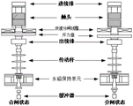
the permanent magnet maintaining unit comprises an upper polar plate, a pre-compression spring, a rated opening coil, a rated closing coil, a side plate, a permanent magnet fixing support, a movable iron core, a fixing support and a lower polar plate; the upper polar plate, the lower polar plate and the side plate form a unit main body; the permanent magnet is fixed between the rated opening coil and the rated closing coil through a permanent magnet fixing support; the movable iron core is positioned between the upper polar plate and the lower polar plate and is attracted with the upper polar plate through a magnetic field generated by discharge of a rated closing coil or attracted with the lower polar plate through a magnetic field generated by discharge of a rated opening coil; the precompression spring is connected with the movable iron core and is pressed at the lower end of the transmission rod.
Preferably, when short-circuit brake opening is needed, the quick brake opening coil generates electromagnetic repulsion force, the electromagnetic repulsion force forces the repulsion plate to push the transmission rod, the transmission rod compresses the pre-compression spring and pushes the movable iron core to be attracted with the lower pole plate, and short-circuit brake opening is completed.
Preferably, when rated opening is needed, the rated opening coil generates a first magnetic field between the movable iron core and the lower pole plate, and the movable iron core is attracted with the lower pole plate under the action of the first magnetic field to complete rated opening; when rated switching-on is needed, a second magnetic field is generated between the movable iron core and the upper pole plate by the rated switching-on coil, and the movable iron core is attracted with the upper pole plate under the action of the second magnetic field to finish the rated switching-on.
The present disclosure also provides a circuit breaker, comprising a vacuum bulb, a moving contact and an operating mechanism; wherein the content of the first and second substances,
the operating mechanism comprises an electromagnetic repulsion unit for short circuit opening and a permanent magnet maintaining unit for rated opening and rated closing;
the electromagnetic repulsion unit comprises a repulsion plate, a quick opening coil and a transmission rod; the quick opening coil is arranged above the repulsion plate and keeps a certain gap with the repulsion plate; the transmission rod is connected below the repulsion plate;
the permanent magnet maintaining unit comprises an upper polar plate, a pre-compression spring, a rated opening coil, a rated closing coil, a side plate, a permanent magnet fixing support, a movable iron core, a fixing support and a lower polar plate; the upper polar plate, the lower polar plate and the side plate form a unit main body; the permanent magnet is fixed between the rated opening coil and the rated closing coil through a permanent magnet fixing support; the movable iron core is positioned between the upper polar plate and the lower polar plate and is attracted with the upper polar plate through a magnetic field generated by discharge of a rated closing coil or attracted with the lower polar plate through a magnetic field generated by discharge of a rated opening coil; the pre-compression spring is connected with the movable iron core and is in compression joint with the lower end of the transmission rod;
one side of the moving contact is connected with the repulsion plate through threads, and the other side of the moving contact is connected with one side of the vacuum bubble;
preferably, when short-circuit brake opening is needed, the quick brake opening coil generates electromagnetic repulsion force, the electromagnetic repulsion force forces the repulsion plate to push the transmission rod, the transmission rod compresses the pre-compression spring and pushes the movable iron core to be attracted with the lower pole plate, and short-circuit brake opening is completed.
Preferably, when rated opening is needed, the rated opening coil generates a first magnetic field between the movable iron core and the lower pole plate, and the movable iron core is attracted with the lower pole plate under the action of the first magnetic field to complete rated opening; when rated switching-on is needed, a second magnetic field is generated between the movable iron core and the upper pole plate by the rated switching-on coil, and the movable iron core is attracted with the upper pole plate under the action of the second magnetic field to finish the rated switching-on.
Preferably, the circuit breaker further comprises a buffer mechanism connected with the permanent magnet holding unit through a flange, the buffer mechanism comprises a buffer and a stop sleeve wrapped on the outer side of the buffer, and the buffer is fixed on a buffer fixing plate through a fixing nut.
Preferably, the buffer comprises any one of: oil buffer, damping buffer, spring buffer.
Preferably, the circuit breaker further comprises an incoming line copper bar and an outgoing line copper bar; the wire inlet copper bar is connected with the other side of the vacuum bubble, and the wire outlet copper bar is located at the joint of the repulsion plate and the transmission rod.
Preferably, the circuit breaker further comprises a supporting and fixing assembly, wherein the supporting and fixing assembly comprises an epoxy drawing rod, an insulating fixing plate, an insulating supporting sleeve, a supporting aluminum cylinder and an angle iron bracket; the epoxy drawing rod surrounds the outer side of the vacuum bulb, the insulating fixing plate is located on the outer side of the transmission rod, the insulating supporting sleeve is located between the quick opening coil and the repulsion coil, the supporting aluminum cylinder is located between the repulsion coil and the quick opening coil, and the angle iron support is connected with the buffer fixing plate.
Compared with the prior art, the beneficial effect that this disclosure brought does: the permanent magnet holding unit provides large opening and closing holding force to realize rated opening and rated closing, and can meet the requirement of large current tolerance during breaking; meanwhile, rapid brake opening can be realized through the electromagnetic repulsion unit, the response speed of the operating mechanism is improved, the transmission time of the electromagnetic repulsion on each part is reduced, and the requirements of high-capacity direct current short circuit breaking and rated breaking can be met.
Drawings
Fig. 1 is a schematic structural diagram of a quick switch operating mechanism combining permanent magnets and repulsive force according to an embodiment of the present disclosure;
fig. 2 is a schematic structural diagram of a permanent magnet holding unit according to another embodiment of the present disclosure;
fig. 3 is a schematic mechanism diagram of a circuit breaker provided by another embodiment of the present disclosure;
fig. 4 is a schematic structural view of a connection between a repulsive disc and a movable contact according to another embodiment of the present disclosure;
FIG. 5 is a schematic illustration of a rated opening provided by another embodiment of the present disclosure;
fig. 6 is a schematic diagram of a rated closing according to another embodiment of the present disclosure.
The designations in the figures illustrate the following:
1-incoming copper bar; 2-vacuum bubble; 3-epoxy drawing bar; 4-supporting the aluminum cylinder; 5-fast opening coil; 6-a line outlet copper bar; 7-an insulating fixing plate; 8-a transmission rod; 9-a permanent magnet holding unit; 10-a flange; 11-a buffer mechanism; 12-a buffer retainer plate; 13-a fixing nut; 14-angle iron bracket; 15-repulsive force plate; 16-an insulating support sleeve; 17-an upper polar plate; 18-a pre-compressed spring; 19-rated opening coil; 20-side plate; 21-a permanent magnet; 22-a permanent magnet fixing support; 23-a movable iron core; 24-rated closing coil; 25-lower pole plate.
Detailed Description
Specific embodiments of the present disclosure will be described in detail below with reference to fig. 1 to 6. While specific embodiments of the disclosure are shown in the drawings, it should be understood that the disclosure may be embodied in various forms and should not be limited to the embodiments set forth herein. Rather, these embodiments are provided so that this disclosure will be thorough and complete, and will fully convey the scope of the disclosure to those skilled in the art.
It should be noted that certain terms are used throughout the description and claims to refer to particular components. As one skilled in the art will appreciate, various names may be used to refer to a component. This specification and claims do not intend to distinguish between components that differ in name but not function. In the following description and in the claims, the terms "include" and "comprise" are used in an open-ended fashion, and thus should be interpreted to mean "include, but not limited to. The description which follows is a preferred embodiment of the invention, but is made for the purpose of illustrating the general principles of the invention and not for the purpose of limiting the scope of the invention. The scope of the present disclosure is to be determined by the terms of the appended claims.
To facilitate an understanding of the embodiments of the present disclosure, the following detailed description is to be considered in conjunction with the accompanying drawings, and the drawings are not to be construed as limiting the embodiments of the present disclosure.
In one embodiment, as shown in fig. 1 to 2, a fast opening and closing actuator combining a permanent magnet and a repulsive force includes: the permanent magnet brake system comprises an electromagnetic repulsion unit for short circuit brake opening and a permanent magnet maintaining unit for rated brake opening and rated brake closing; wherein the content of the first and second substances,
the electromagnetic repulsion unit comprises a repulsion plate, a quick opening coil and a transmission rod; the quick opening coil is arranged above the repulsion plate and keeps a certain gap with the repulsion plate; the transmission rod is connected below the repulsion plate;
the permanent magnet maintaining unit comprises an upper polar plate, a pre-compression spring, a rated opening coil, a rated closing coil, a side plate, a permanent magnet fixing support, a movable iron core, a fixing support and a lower polar plate; the upper polar plate, the lower polar plate and the side plate form a unit main body; the permanent magnet is fixed between the rated opening coil and the rated closing coil through a permanent magnet fixing support; the movable iron core is positioned between the upper polar plate and the lower polar plate and is attracted with the upper polar plate through a magnetic field generated by discharge of a rated closing coil or attracted with the lower polar plate through a magnetic field generated by discharge of a rated opening coil; the precompression spring is connected with the movable iron core and is pressed at the lower end of the transmission rod.
In this embodiment, when the operating mechanism needs to perform short-circuit opening, the electromagnetic repulsion unit receives an opening signal, the rapid opening coil discharges to generate an electromagnetic repulsion, the repulsion plate drives the moving contact to push the transmission rod, and the transmission rod compresses the pre-compression spring to push the moving iron core to be attracted with the lower pole plate, so that short-circuit opening is realized. When the operating mechanism needs rated opening, the permanent magnet maintaining unit receives rated opening signals, the rated opening coil discharges to generate a magnetic field, the magnetic field counteracts the magnetic field between the movable iron core and the upper polar plate and simultaneously establishes the magnetic field between the movable iron core and the lower polar plate, the movable iron core is attracted with the lower polar plate under the action of the permanent magnet, and the contact is pulled through the transmission rod in the attracting process to realize rated opening. When the operating mechanism needs to perform rated switching-on, the permanent magnet maintaining unit receives a rated switching-on signal, the rated switching-on coil discharges to generate a magnetic field, the magnetic field counteracts a magnetic field between the movable iron core and the lower pole plate and simultaneously establishes a magnetic field between the movable iron core and the upper pole plate, the movable iron core is attracted with the upper pole plate under the action of the permanent magnet, and the contact is pushed through the transmission rod in the attraction process to realize rated switching-on.
According to the embodiment, the permanent magnet retaining unit provides large opening and closing retaining force to realize rated opening and rated closing, the requirement of large current tolerance during breaking can be met, meanwhile, the electromagnetic repulsion unit can be used for realizing rapid opening, the defect that the service life of the operating mechanism is reduced due to the fact that the repulsion opening mode is adopted for rated opening or short circuit opening in the prior art can be overcome, and the permanent magnet retaining unit has creativity.
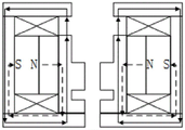
The working principle of the above embodiment is further explained with reference to fig. 5 to 6.
When rated opening operation is required, an external circuit discharges electricity to a rated opening coil through a thyristor to generate pulse current, the pulse current establishes a magnetic field through surrounding ferromagnetic materials, the direction and the path of the magnetic force line are shown as solid arrows in figure 5, the magnetic force line generated by the permanent magnet starts from an N pole, passes through the permanent magnet fixing support, the movable iron core, the lower pole plate and the side plate and finally returns to an S pole of the permanent magnet, the path of the magnetic force line is shown by a dotted arrow in figure 5, the magnetic force line generated by the permanent magnet between the movable iron core and the upper pole plate is counteracted by the magnetic force line generated by the rated opening coil, and the magnetic force line established by the rated opening coil passes through the movable iron core and the lower polar plate, so that the lower polar plate has a powerful effect on the movable iron core, the movable iron core moves towards the direction of the lower polar plate and generates opening retaining force with the lower polar plate, and the movable iron core is connected with the transmission rod through a buckle to drive the contact to realize rated opening. When the closing operation is needed, the pre-charging capacitor discharges electricity to the rated opening coil through the thyristor to generate pulse current, the pulse current establishes a magnetic field through the surrounding ferromagnetic materials, the direction and the path of the magnetic force line are shown as the solid arrow in figure 6, the magnetic force line generated by the permanent magnet starts from the N pole, the permanent magnet fixing support, the movable iron core, the upper pole plate and the side plate finally return to the S pole of the permanent magnet, the path of the magnetic force line is shown by a dotted arrow in fig. 6, the magnetic force line generated by the permanent magnet between the movable iron core and the lower pole plate is counteracted by the magnetic force line generated by the rated closing coil, and the magnetic line of force established by the rated closing coil passes through the movable iron core and the upper polar plate, so that the upper polar plate has a powerful action on the movable iron core, the movable iron core moves towards the upper polar plate and has closing retention force with the upper polar plate, and the movable iron core pushes the transmission rod through the compression spring to push the contact to realize rated closing.
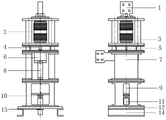
In another embodiment, as shown in fig. 3 to 4, the present disclosure also provides a circuit breaker including a vacuum bulb, a movable contact, and an operating mechanism; wherein the content of the first and second substances,
the operating mechanism comprises an electromagnetic repulsion unit for short circuit opening and a permanent magnet maintaining unit for rated opening and rated closing;
the electromagnetic repulsion unit comprises a repulsion plate, a quick opening coil and a transmission rod; the quick opening coil is arranged above the repulsion plate and keeps a certain gap with the repulsion plate; the transmission rod is connected below the repulsion plate;
the permanent magnet holding unit comprises an upper pole plate 17, a pre-compression spring 18, a rated opening coil 19, a rated closing coil 24, a side plate 20, a permanent magnet 21, a permanent magnet fixing support 22, a movable iron core 23 and a lower pole plate 25; the upper polar plate 17, the lower polar plate 25 and the side plate 20 form a unit main body; the permanent magnet 21 is fixed between the rated opening coil 19 and the rated closing coil 24 through a permanent magnet fixing bracket 22; the movable iron core 23 is positioned between the upper polar plate 17 and the lower polar plate 25, and is attracted with the upper polar plate 17 through a magnetic field generated by discharge of a rated closing coil 24 or attracted with the lower polar plate 25 through a magnetic field generated by discharge of a rated opening coil 19; the precompression spring 18 is connected with the movable iron core 23 and is pressed at the lower end of the transmission rod 8;
one side of the moving contact is connected with the repulsion plate 15 through threads, and the other side is connected with one side of the vacuum bulb 2.
In this embodiment, the repulsion disk 15 is usually directly connected to the moving contact, so that the response speed of the operating mechanism can be increased, and the transmission time of the electromagnetic repulsion on the other components can be reduced.
In another embodiment, the circuit breaker further comprises a buffer mechanism 11 connected with the permanent magnet holding unit through a flange 10, wherein the buffer mechanism 11 comprises a buffer and a stop sleeve wrapped outside the buffer, and the buffer is fixed on a buffer fixing plate through a fixing nut.
In this embodiment, for example, the initial distance between the buffer and the operating mechanism is set to 7mm, the movement stroke of the movable iron core is set to 15mm, and in the opening process, when the movement of the movable iron core exceeds 15mm, the contact and the upper pole plate limit the operating mechanism; in the closing process, when the moving iron core moves to exceed 15mm, the lower pole plate and the stopping sleeve limit the operating mechanism.
In another embodiment, the buffer comprises any one of: oil buffer, damping buffer, spring buffer.
In another embodiment, the circuit breaker further comprises an incoming line copper bar 1 and an outgoing line copper bar 6; the wire inlet copper bar 1 is connected with the other side of the vacuum bulb 2, and the wire outlet copper bar 6 is located at the connection position of the repulsion plate 15 and the transmission rod 8.
In another embodiment, the circuit breaker further comprises a supporting and fixing assembly, wherein the supporting and fixing assembly comprises an epoxy drawing rod 3, an insulating fixing plate 7, an insulating supporting sleeve 16, a supporting aluminum cylinder 4 and an angle iron bracket 14; the epoxy drawing rod 3 surrounds the outer side of the vacuum bulb 2, the insulating fixing plate 7 is located on the outer side of the transmission rod 8, the insulating support sleeve 16 is located between the quick opening coil 5 and the repulsion plate 15, the support aluminum cylinder 4 is located between the repulsion plate 15 and the quick opening coil 5, and the angle iron support 14 is connected with the buffer fixing plate 12.
Although the present disclosure has been described with reference to a preferred embodiment, it will be understood by those skilled in the art that various changes may be made and equivalents may be substituted for elements thereof without departing from the scope of the present disclosure.
Claims (9)
1. A permanent magnetism and repulsion force combined fast switch operating mechanism for improving the opening and closing holding force comprises: the permanent magnet brake system comprises an electromagnetic repulsion unit for short circuit brake opening and a permanent magnet maintaining unit for rated brake opening and rated brake closing; wherein the content of the first and second substances,
the electromagnetic repulsion unit comprises a repulsion plate, a quick opening coil and a transmission rod; the quick opening coil is arranged above the repulsion plate and keeps a certain gap with the repulsion plate; one end of the transmission rod is directly connected below the repulsion plate;
the permanent magnet maintaining unit comprises an upper polar plate, a pre-compression spring, a rated opening coil, a rated closing coil, a side plate, a permanent magnet fixing support, a movable iron core, a fixing support and a lower polar plate; the upper polar plate, the lower polar plate and the side plate form a unit main body; the permanent magnet is fixed between the rated opening coil and the rated closing coil through a permanent magnet fixing support; the movable iron core is positioned between the upper polar plate and the lower polar plate and is attracted with the upper polar plate through a magnetic field generated by discharge of a rated closing coil or attracted with the lower polar plate through a magnetic field generated by discharge of a rated opening coil, wherein when rated opening is needed, the rated opening coil generates a first magnetic field between the movable iron core and the lower polar plate, and the movable iron core is attracted with the lower polar plate under the action of the first magnetic field to complete rated opening; when rated switching-on is needed, a rated switching-on coil generates a second magnetic field between the movable iron core and the upper polar plate, and the movable iron core is attracted with the upper polar plate under the action of the second magnetic field to finish the rated switching-on; the precompression spring is connected with the movable iron core and directly pressed on the other end of the transmission rod.
2. The operating mechanism according to claim 1, wherein when short-circuit opening is required, the fast opening coil generates electromagnetic repulsion force, the electromagnetic repulsion force forces the repulsion plate to push the transmission rod, and the transmission rod compresses the pre-compression spring and pushes the movable iron core to attract the lower pole plate, thereby completing short-circuit opening.
3. A circuit breaker comprises a vacuum bubble, a moving contact and an operating mechanism; wherein the content of the first and second substances,
the operating mechanism comprises an electromagnetic repulsion unit for short circuit opening and a permanent magnet maintaining unit for rated opening and rated closing;
the electromagnetic repulsion unit comprises a repulsion disc, a quick opening coil and a transmission rod; the quick opening coil is arranged above the repulsion plate and keeps a certain gap with the repulsion plate; the transmission rod is connected below the repulsion plate;
the permanent magnet maintaining unit comprises an upper polar plate, a pre-compression spring, a rated opening coil, a rated closing coil, a side plate, a permanent magnet fixing support, a movable iron core, a fixing support and a lower polar plate; the upper polar plate, the lower polar plate and the side plate form a unit main body; the permanent magnet is fixed between the rated opening coil and the rated closing coil through a permanent magnet fixing support; the movable iron core is positioned between the upper polar plate and the lower polar plate and is attracted with the upper polar plate through a magnetic field generated by discharge of a rated closing coil or attracted with the lower polar plate through a magnetic field generated by discharge of a rated opening coil; the pre-compression spring is connected with the movable iron core and is in compression joint with the lower end of the transmission rod;
one side of the moving contact is connected with the repulsion plate through threads, and the other side of the moving contact is connected with one side of the vacuum bubble.
4. The circuit breaker according to claim 3, wherein when short-circuit opening is required, the fast opening coil generates electromagnetic repulsion force, the electromagnetic repulsion force forces the repulsion plate to push the transmission rod, and the transmission rod compresses the pre-compression spring and pushes the movable iron core to attract the lower pole plate, thereby completing short-circuit opening.
5. The circuit breaker according to claim 3, wherein when rated opening is required, the rated opening coil generates a first magnetic field between the movable iron core and the lower pole plate, and the movable iron core is attracted with the lower pole plate under the action of the first magnetic field to complete rated opening; when rated switching-on is needed, a second magnetic field is generated between the movable iron core and the upper pole plate by the rated switching-on coil, and the movable iron core is attracted with the upper pole plate under the action of the second magnetic field to complete rated switching-on.
6. The circuit breaker of claim 3, wherein the circuit breaker further comprises a buffer mechanism connected with the permanent magnet holding unit through a flange, the buffer mechanism comprises a buffer and a stop sleeve wrapped outside the buffer, and the buffer is fixed on the buffer fixing plate through a fixing nut.
7. The circuit breaker of claim 6, wherein the snubber comprises any one of: oil buffer, damping buffer, spring buffer.
8. The circuit breaker of claim 3, wherein the circuit breaker further comprises an incoming copper bar and an outgoing copper bar; the wire inlet copper bar is connected with the other side of the vacuum bubble, and the wire outlet copper bar is located at the joint of the repulsion plate and the transmission rod.
9. The circuit breaker of claim 6, wherein the circuit breaker further comprises a supporting and fixing assembly, the supporting and fixing assembly comprising an epoxy draw bar, an insulating fixing plate, an insulating supporting sleeve, a supporting aluminum cylinder and an angle iron bracket; the epoxy drawing rod surrounds the outer side of the vacuum bulb, the insulating fixing plate is located on the outer side of the transmission rod, the insulating supporting sleeve is located between the rapid opening coil and the repulsion plate, the supporting aluminum barrel is located between the repulsion plate and the rapid opening coil, and the angle iron support is connected with the buffer fixing plate.
Priority Applications (1)
| Application Number | Priority Date | Filing Date | Title |
|---|---|---|---|
| CN202010707493.8A CN112071723B (en) | 2020-07-21 | 2020-07-21 | Permanent magnet and repulsion force combined quick switch operating mechanism |
Applications Claiming Priority (1)
| Application Number | Priority Date | Filing Date | Title |
|---|---|---|---|
| CN202010707493.8A CN112071723B (en) | 2020-07-21 | 2020-07-21 | Permanent magnet and repulsion force combined quick switch operating mechanism |
Publications (2)
| Publication Number | Publication Date |
|---|---|
| CN112071723A CN112071723A (en) | 2020-12-11 |
| CN112071723B true CN112071723B (en) | 2022-06-21 |
Family
ID=73657531
Family Applications (1)
| Application Number | Title | Priority Date | Filing Date |
|---|---|---|---|
| CN202010707493.8A Active CN112071723B (en) | 2020-07-21 | 2020-07-21 | Permanent magnet and repulsion force combined quick switch operating mechanism |
Country Status (1)
| Country | Link |
|---|---|
| CN (1) | CN112071723B (en) |
Families Citing this family (7)
| Publication number | Priority date | Publication date | Assignee | Title |
|---|---|---|---|---|
| CN112802721B (en) * | 2020-12-31 | 2022-11-01 | 国网宁夏电力有限公司电力科学研究院 | Long-stroke hybrid quick operating mechanism for high-voltage circuit breaker |
| CN112951651A (en) * | 2021-01-28 | 2021-06-11 | 中国人民解放军海军工程大学 | Short-circuit current self-driven quick switch |
| CN112821348A (en) * | 2021-01-28 | 2021-05-18 | 中国人民解放军海军工程大学 | Short-circuit current self-driven current-limiting direct current breaker |
| CN113257644B (en) * | 2021-05-10 | 2023-03-10 | 北京中磁新材科技有限公司 | Combined circuit breaker operating mechanism for ultra-fast opening |
| CN113675047A (en) * | 2021-08-12 | 2021-11-19 | 常州博瑞电力自动化设备有限公司 | Compact electromagnetic repulsion force operating mechanism and three-phase switch using same |
| CN114388316B (en) * | 2021-12-24 | 2024-03-12 | 上海京硅智能技术有限公司 | Circuit breaker contact system |
| CN116053094B (en) * | 2023-03-31 | 2023-05-30 | 清华大学 | Quick mechanical switch operating mechanism with adjustable opening speed and control method thereof |
Family Cites Families (11)
| Publication number | Priority date | Publication date | Assignee | Title |
|---|---|---|---|---|
| CN1046815C (en) * | 1991-10-04 | 1999-11-24 | 张凡 | Magnetic-keeping magnet |
| CN101315836B (en) * | 2008-06-17 | 2010-07-21 | 西安交通大学 | Electromagnetic repulsion force system and permanent magnetic system coupled self-adapting control mechanism |
| CN201788887U (en) * | 2010-07-27 | 2011-04-06 | 国网电力科学研究院 | Direct-acting vacuum breaker equipped with bistable permanent-magnetic operating mechanism |
| CN101986407B (en) * | 2010-12-06 | 2013-01-30 | 东南大学 | Quick control mechanism of ultrahigh pressure vacuum circuit breaker and control method thereof |
| CN204189698U (en) * | 2014-10-10 | 2015-03-04 | 珠海许继电气有限公司 | A kind of Standard type intelligent breaker complete set of equipments of self-supply power source |
| CN105149199B (en) * | 2015-07-14 | 2018-05-15 | 北京卫星环境工程研究所 | The electromagnetic vibration generator system used under spacecraft dynamics apocarpy |
| CN105609364A (en) * | 2015-09-02 | 2016-05-25 | 中国西电电气股份有限公司 | High-speed switching-off vacuum switch |
| CN106409607B (en) * | 2016-11-30 | 2018-09-25 | 滁州学院 | The permanent-magnet breaker divide-shut brake intelligent control module of the simple and quick switch type of relay |
| CN107146735A (en) * | 2017-07-11 | 2017-09-08 | 哈尔滨理工大学 | High-pressure vacuum breaker permanent-magnet manipulating mechanism based on electromagnetic repulsion force principle |
| CN107833783B (en) * | 2017-09-21 | 2019-06-11 | 西安交通大学 | A kind of powder operation device and its actuating method of dc circuit breaker |
| CN108644297A (en) * | 2018-05-21 | 2018-10-12 | 西北工业大学 | A kind of parallel MR damper of small amplitude based on bipolar plates |
-
2020
- 2020-07-21 CN CN202010707493.8A patent/CN112071723B/en active Active
Also Published As
| Publication number | Publication date |
|---|---|
| CN112071723A (en) | 2020-12-11 |
Similar Documents
| Publication | Publication Date | Title |
|---|---|---|
| CN112071723B (en) | Permanent magnet and repulsion force combined quick switch operating mechanism | |
| CN102290279A (en) | High speed vacuum direct current (DC) current limiting circuit breaker | |
| CN107833783A (en) | The powder operation device and its actuating method of a kind of dc circuit breaker | |
| CN112510647A (en) | Direct current breaker combining oscillation transfer and solid-state switch | |
| CN107146735A (en) | High-pressure vacuum breaker permanent-magnet manipulating mechanism based on electromagnetic repulsion force principle | |
| CN116798804A (en) | Medium-voltage rapid mechanical switch and switching-on and switching-off method | |
| CN201417683Y (en) | Control circuit of bistable permanent magnetic actuator | |
| CN208580703U (en) | Mechanical high-speed switch based on electromagnetic repulsion mechanism | |
| CN104851740A (en) | Long stroke permanent magnetic actuator with auxiliary coil for high-voltage vacuum circuit breaker | |
| CN110875162A (en) | Mechanical quick switch based on electromagnetic repulsion mechanism | |
| CN112490070A (en) | Electromagnetic repulsion mechanism based on double-repulsion disc | |
| CN205069539U (en) | Communication circuit breaker of good reliability | |
| CN101980347B (en) | Circuit for restraining switching-on and switching-off bounce of electromagnetic repulsion fast vacuum circuit breaker | |
| CN201387819Y (en) | Permanent magnetic operating mechanism of electric switch | |
| CN214378214U (en) | Pulse type contactor | |
| CN113593943A (en) | High-current rapid mechanical switch structure and control method thereof | |
| CN110752112B (en) | Bistable ultrahigh-speed operating mechanism, direct-current circuit breaker and control method | |
| CN109473309A (en) | A kind of vacuum circuit breaker with electromagnetism buffer gear | |
| CN2870134Y (en) | Intelligent phase-selection indoor high-pressure vacuum circuit breaker | |
| CN2251780Y (en) | Half-hard magnet electromagnet and control circuit thereof | |
| CN203721619U (en) | Intelligent type horizontal wire incoming and outgoing vacuum circuit breaker | |
| CN114639572B (en) | Compact electromagnetic repulsion mechanism of integrated diaphragm spring | |
| CN214505376U (en) | Circuit that rebounds is prevented in circuit breaker divide-shut brake | |
| CN2626038Y (en) | Dual coil bistable permanent magnet operation mechanism | |
| CN107591278B (en) | A kind of semiaxis buckle-type monostable operating mechanism and its actuating method |
Legal Events
| Date | Code | Title | Description |
|---|---|---|---|
| PB01 | Publication | ||
| PB01 | Publication | ||
| SE01 | Entry into force of request for substantive examination | ||
| SE01 | Entry into force of request for substantive examination | ||
| GR01 | Patent grant | ||
| GR01 | Patent grant |