CN112004640B - Polishing apparatus and polishing system provided with surface texture measuring apparatus for polishing pad - Google Patents
Polishing apparatus and polishing system provided with surface texture measuring apparatus for polishing pad Download PDFInfo
- Publication number
- CN112004640B CN112004640B CN201980026985.6A CN201980026985A CN112004640B CN 112004640 B CN112004640 B CN 112004640B CN 201980026985 A CN201980026985 A CN 201980026985A CN 112004640 B CN112004640 B CN 112004640B
- Authority
- CN
- China
- Prior art keywords
- polishing
- polishing pad
- surface texture
- dressing
- texture measuring
- Prior art date
- Legal status (The legal status is an assumption and is not a legal conclusion. Google has not performed a legal analysis and makes no representation as to the accuracy of the status listed.)
- Active
Links
- 238000005498 polishing Methods 0.000 title claims abstract description 628
- 238000012545 processing Methods 0.000 claims description 96
- 230000007246 mechanism Effects 0.000 claims description 80
- 238000005259 measurement Methods 0.000 claims description 76
- 238000003384 imaging method Methods 0.000 claims description 44
- 238000012549 training Methods 0.000 claims description 18
- 238000003860 storage Methods 0.000 claims description 14
- 238000006073 displacement reaction Methods 0.000 claims description 13
- 238000000227 grinding Methods 0.000 claims description 13
- 238000009966 trimming Methods 0.000 claims description 4
- 230000001678 irradiating effect Effects 0.000 claims description 2
- 239000007921 spray Substances 0.000 claims description 2
- 238000003801 milling Methods 0.000 claims 1
- 238000002834 transmittance Methods 0.000 claims 1
- 239000000758 substrate Substances 0.000 abstract description 34
- 239000004065 semiconductor Substances 0.000 abstract description 14
- 239000007788 liquid Substances 0.000 description 37
- 239000007789 gas Substances 0.000 description 36
- 238000010586 diagram Methods 0.000 description 22
- 230000005856 abnormality Effects 0.000 description 19
- 238000009826 distribution Methods 0.000 description 18
- 239000012530 fluid Substances 0.000 description 18
- 238000013473 artificial intelligence Methods 0.000 description 14
- 238000000034 method Methods 0.000 description 14
- 230000008859 change Effects 0.000 description 13
- 230000006870 function Effects 0.000 description 13
- VYPSYNLAJGMNEJ-UHFFFAOYSA-N Silicium dioxide Chemical compound O=[Si]=O VYPSYNLAJGMNEJ-UHFFFAOYSA-N 0.000 description 12
- 238000004364 calculation method Methods 0.000 description 12
- 230000003750 conditioning effect Effects 0.000 description 12
- 239000010408 film Substances 0.000 description 12
- 230000002159 abnormal effect Effects 0.000 description 9
- 238000003745 diagnosis Methods 0.000 description 8
- 230000004888 barrier function Effects 0.000 description 7
- 238000013135 deep learning Methods 0.000 description 7
- 238000010801 machine learning Methods 0.000 description 7
- 230000003287 optical effect Effects 0.000 description 7
- 230000002093 peripheral effect Effects 0.000 description 7
- 230000008569 process Effects 0.000 description 7
- 238000001228 spectrum Methods 0.000 description 7
- IJGRMHOSHXDMSA-UHFFFAOYSA-N Atomic nitrogen Chemical compound N#N IJGRMHOSHXDMSA-UHFFFAOYSA-N 0.000 description 6
- 229910001873 dinitrogen Inorganic materials 0.000 description 6
- 238000012423 maintenance Methods 0.000 description 6
- 238000012986 modification Methods 0.000 description 6
- 230000004048 modification Effects 0.000 description 6
- 235000012239 silicon dioxide Nutrition 0.000 description 6
- 239000000377 silicon dioxide Substances 0.000 description 6
- 238000013528 artificial neural network Methods 0.000 description 5
- 230000005540 biological transmission Effects 0.000 description 5
- 230000000875 corresponding effect Effects 0.000 description 5
- 239000002245 particle Substances 0.000 description 5
- 229910000420 cerium oxide Inorganic materials 0.000 description 4
- 238000004891 communication Methods 0.000 description 4
- 230000001965 increasing effect Effects 0.000 description 4
- BMMGVYCKOGBVEV-UHFFFAOYSA-N oxo(oxoceriooxy)cerium Chemical compound [Ce]=O.O=[Ce]=O BMMGVYCKOGBVEV-UHFFFAOYSA-N 0.000 description 4
- 239000002002 slurry Substances 0.000 description 4
- 229910052751 metal Inorganic materials 0.000 description 3
- 239000002184 metal Substances 0.000 description 3
- 239000000203 mixture Substances 0.000 description 3
- 238000007517 polishing process Methods 0.000 description 3
- 239000000126 substance Substances 0.000 description 3
- 239000006061 abrasive grain Substances 0.000 description 2
- 238000013459 approach Methods 0.000 description 2
- 230000000295 complement effect Effects 0.000 description 2
- 230000001143 conditioned effect Effects 0.000 description 2
- 230000001276 controlling effect Effects 0.000 description 2
- 239000010949 copper Substances 0.000 description 2
- 230000003247 decreasing effect Effects 0.000 description 2
- 238000007599 discharging Methods 0.000 description 2
- 230000000694 effects Effects 0.000 description 2
- 230000003028 elevating effect Effects 0.000 description 2
- 230000010354 integration Effects 0.000 description 2
- 229910044991 metal oxide Inorganic materials 0.000 description 2
- 150000004706 metal oxides Chemical class 0.000 description 2
- 239000003595 mist Substances 0.000 description 2
- 239000013307 optical fiber Substances 0.000 description 2
- 238000003825 pressing Methods 0.000 description 2
- 239000010936 titanium Substances 0.000 description 2
- RYGMFSIKBFXOCR-UHFFFAOYSA-N Copper Chemical compound [Cu] RYGMFSIKBFXOCR-UHFFFAOYSA-N 0.000 description 1
- 208000036829 Device dislocation Diseases 0.000 description 1
- RTAQQCXQSZGOHL-UHFFFAOYSA-N Titanium Chemical compound [Ti] RTAQQCXQSZGOHL-UHFFFAOYSA-N 0.000 description 1
- 230000008033 biological extinction Effects 0.000 description 1
- 239000000919 ceramic Substances 0.000 description 1
- 239000013256 coordination polymer Substances 0.000 description 1
- 229910052802 copper Inorganic materials 0.000 description 1
- 238000012937 correction Methods 0.000 description 1
- 230000002596 correlated effect Effects 0.000 description 1
- 238000005520 cutting process Methods 0.000 description 1
- 230000007423 decrease Effects 0.000 description 1
- 239000008367 deionised water Substances 0.000 description 1
- 229910021641 deionized water Inorganic materials 0.000 description 1
- 238000001514 detection method Methods 0.000 description 1
- 230000002542 deteriorative effect Effects 0.000 description 1
- 229910003460 diamond Inorganic materials 0.000 description 1
- 239000010432 diamond Substances 0.000 description 1
- 239000000428 dust Substances 0.000 description 1
- 238000004070 electrodeposition Methods 0.000 description 1
- 230000002349 favourable effect Effects 0.000 description 1
- 239000011521 glass Substances 0.000 description 1
- 230000010365 information processing Effects 0.000 description 1
- 238000009434 installation Methods 0.000 description 1
- 238000004519 manufacturing process Methods 0.000 description 1
- 238000000206 photolithography Methods 0.000 description 1
- 229910052715 tantalum Inorganic materials 0.000 description 1
- GUVRBAGPIYLISA-UHFFFAOYSA-N tantalum atom Chemical compound [Ta] GUVRBAGPIYLISA-UHFFFAOYSA-N 0.000 description 1
- 230000002123 temporal effect Effects 0.000 description 1
- 239000010409 thin film Substances 0.000 description 1
- 229910052719 titanium Inorganic materials 0.000 description 1
- WFKWXMTUELFFGS-UHFFFAOYSA-N tungsten Chemical compound [W] WFKWXMTUELFFGS-UHFFFAOYSA-N 0.000 description 1
- 229910052721 tungsten Inorganic materials 0.000 description 1
- 239000010937 tungsten Substances 0.000 description 1
- XLYOFNOQVPJJNP-UHFFFAOYSA-N water Chemical compound O XLYOFNOQVPJJNP-UHFFFAOYSA-N 0.000 description 1
Images


Classifications
-
- B—PERFORMING OPERATIONS; TRANSPORTING
- B24—GRINDING; POLISHING
- B24B—MACHINES, DEVICES, OR PROCESSES FOR GRINDING OR POLISHING; DRESSING OR CONDITIONING OF ABRADING SURFACES; FEEDING OF GRINDING, POLISHING, OR LAPPING AGENTS
- B24B49/00—Measuring or gauging equipment for controlling the feed movement of the grinding tool or work; Arrangements of indicating or measuring equipment, e.g. for indicating the start of the grinding operation
- B24B49/12—Measuring or gauging equipment for controlling the feed movement of the grinding tool or work; Arrangements of indicating or measuring equipment, e.g. for indicating the start of the grinding operation involving optical means
-
- B—PERFORMING OPERATIONS; TRANSPORTING
- B24—GRINDING; POLISHING
- B24B—MACHINES, DEVICES, OR PROCESSES FOR GRINDING OR POLISHING; DRESSING OR CONDITIONING OF ABRADING SURFACES; FEEDING OF GRINDING, POLISHING, OR LAPPING AGENTS
- B24B37/00—Lapping machines or devices; Accessories
- B24B37/005—Control means for lapping machines or devices
-
- B—PERFORMING OPERATIONS; TRANSPORTING
- B24—GRINDING; POLISHING
- B24B—MACHINES, DEVICES, OR PROCESSES FOR GRINDING OR POLISHING; DRESSING OR CONDITIONING OF ABRADING SURFACES; FEEDING OF GRINDING, POLISHING, OR LAPPING AGENTS
- B24B37/00—Lapping machines or devices; Accessories
- B24B37/34—Accessories
-
- B—PERFORMING OPERATIONS; TRANSPORTING
- B24—GRINDING; POLISHING
- B24B—MACHINES, DEVICES, OR PROCESSES FOR GRINDING OR POLISHING; DRESSING OR CONDITIONING OF ABRADING SURFACES; FEEDING OF GRINDING, POLISHING, OR LAPPING AGENTS
- B24B53/00—Devices or means for dressing or conditioning abrasive surfaces
- B24B53/017—Devices or means for dressing, cleaning or otherwise conditioning lapping tools
-
- H—ELECTRICITY
- H01—ELECTRIC ELEMENTS
- H01L—SEMICONDUCTOR DEVICES NOT COVERED BY CLASS H10
- H01L21/00—Processes or apparatus adapted for the manufacture or treatment of semiconductor or solid state devices or of parts thereof
- H01L21/67—Apparatus specially adapted for handling semiconductor or electric solid state devices during manufacture or treatment thereof; Apparatus specially adapted for handling wafers during manufacture or treatment of semiconductor or electric solid state devices or components ; Apparatus not specifically provided for elsewhere
- H01L21/67005—Apparatus not specifically provided for elsewhere
- H01L21/67011—Apparatus for manufacture or treatment
- H01L21/67092—Apparatus for mechanical treatment
Landscapes
- Engineering & Computer Science (AREA)
- Mechanical Engineering (AREA)
- Physics & Mathematics (AREA)
- Condensed Matter Physics & Semiconductors (AREA)
- General Physics & Mathematics (AREA)
- Manufacturing & Machinery (AREA)
- Computer Hardware Design (AREA)
- Microelectronics & Electronic Packaging (AREA)
- Power Engineering (AREA)
- Finish Polishing, Edge Sharpening, And Grinding By Specific Grinding Devices (AREA)
- Mechanical Treatment Of Semiconductor (AREA)
- Constituent Portions Of Griding Lathes, Driving, Sensing And Control (AREA)
- Grinding-Machine Dressing And Accessory Apparatuses (AREA)
Abstract
The present invention relates to a polishing apparatus including a surface texture measuring device for measuring surface textures of a polishing pad used for polishing a substrate such as a semiconductor wafer, and a polishing system including the polishing apparatus. The polishing device is provided with: a surface property measuring device (30) for measuring the surface property of the polishing pad (2); a support arm (50) for supporting the surface texture measuring device (30); and a moving means (53) connected to the support arm (50) for automatically moving the surface texture measuring device (30) from the standby position to the measuring position.
Description
Technical Field
The present invention relates to a polishing apparatus including a surface texture measuring device for measuring surface textures of a polishing pad used for polishing a substrate such as a semiconductor wafer, and a polishing system including the polishing apparatus.
Background
In recent years, with the increase in integration and density of semiconductor devices, wiring lines of circuits have become finer and the number of layers of multilayer wiring lines has increased. In order to miniaturize a circuit and realize a multilayer wiring, since the step becomes larger in accordance with the surface unevenness of the lower layer, the film coverage (step coverage) with respect to the step shape is deteriorated when forming a thin film as the number of wiring layers increases. Therefore, in order to perform multilayer wiring, it is necessary to improve the step coverage and perform planarization treatment in a proper process. Further, since the photolithography is miniaturized and the depth of focus is reduced, it is necessary to planarize the surface of the semiconductor device so that the surface irregularities of the semiconductor device are reduced to the depth of focus or less.
Therefore, in the manufacturing process of semiconductor devices, a technique for planarizing the surface of the semiconductor device is becoming more and more important. The most important technique among the planarization techniques is chemical mechanical polishing (CPM). The chemical mechanical polishing uses a polishing apparatus, in which polishing liquid is supplied onto a polishing pad, and a substrate such as a semiconductor wafer is polished by bringing the substrate into sliding contact with the polishing pad. The polishing liquid contains, for example, silicon dioxide (SiO) 2 ) And cerium oxide (CeO) 2 ) And a slurry of abrasive particles.
The polishing apparatus for performing the CMP (chemical mechanical polishing) includes: a polishing table having a polishing pad; and a substrate holding device called a carrier or a top ring for holding a semiconductor wafer (substrate). Such a polishing apparatus is used to polish an insulating film, a metal film, or the like on a substrate by holding the substrate by a substrate holding device and pressing the substrate against a polishing pad at a predetermined pressure.
When a substrate is polished, abrasive grains and abrasive dust adhere to the surface of the polishing pad, and the surface shape and state of the polishing pad change, thereby deteriorating polishing performance. Therefore, as the polishing of the substrate is repeated, the polishing rate is decreased or uneven polishing occurs. Therefore, in order to regenerate the surface shape and state of the deteriorated polishing pad, the polishing pad is dressed (adjusted) using a dresser.
The surface shape and condition of the polishing pad, i.e., the surface texture of the polishing pad, are an important factor in determining CMP performance. Therefore, it is desirable to directly measure the surface properties of the polishing pad and reflect the measured values on the dressing conditions. Therefore, in the conventional polishing apparatus, the dressing condition is determined by using an apparatus for directly measuring the surface properties of the polishing pad. In the present specification, an apparatus for measuring the surface properties of a polishing pad is referred to as a "surface property measuring apparatus".
Documents of the prior art
Patent literature
Patent document 1: international laid-open publication No. 2016/111335
However, conventional polishing apparatuses do not always have a surface texture measuring device installed therein. That is, the surface texture measuring device is attached to the polishing apparatus when the surface texture of the polishing pad is to be measured, and detached after the surface texture of the polishing pad is measured.
FIG. 30 is a schematic view showing an example of a conventional surface texture measuring apparatus attached to a polishing apparatus. As shown in fig. 30, the polishing apparatus includes a holding plate 215 configured as a removable surface texture measuring apparatus 230, and the holding plate 215 is suspended from a frame (not shown) of the polishing apparatus. When the surface texture of the polishing pad 202 is measured, the operator attaches the surface texture measuring device 230 to the lower end of the holding plate 215 after stopping the operation of the polishing apparatus. When the measurement of the surface texture of the polishing pad 202 is completed, the operator detaches the surface texture measuring apparatus 230 from the holding plate 215 and then starts the operation of the polishing apparatus.
In this way, the conventional polishing apparatus measures the surface properties of the polishing pad 202 as a separate operation from the operation of the polishing apparatus. Therefore, in the conventional polishing apparatus, in order to measure the surface properties of the polishing pad 202, the operation of the polishing apparatus needs to be temporarily stopped, and thus the throughput of the polishing apparatus is reduced. Further, since the work of attaching and detaching the surface texture measuring device 230 is very troublesome for the operator and takes time, a polishing device capable of automatically measuring the surface texture of the polishing pad 202 is desired.
Disclosure of Invention
Accordingly, an object of the present invention is to provide a polishing apparatus capable of automatically measuring the surface properties of a polishing pad and improving the output of the polishing apparatus. Furthermore, it is a feature of the present invention to provide a polishing system including such a polishing apparatus.
One aspect of the present invention is a polishing apparatus including: a surface texture measuring device for measuring the surface texture of the polishing pad; a support arm that supports the surface texture measuring device; and a moving means connected to the support arm for automatically moving the surface texture measuring device from a standby position to a measuring position.
The invention is characterized in that: the mobile unit is provided with: a fixed block fixed to the grinding device; a rotating block connected to the support arm; a rotating shaft that rotatably connects the rotating block to the fixed block; and a rotating mechanism that rotates the rotating block.
The invention is characterized in that: the rotary mechanism is a piston cylinder mechanism including a piston connected to the rotary block and a cylinder housing the piston to be movable forward and backward.
The invention is characterized in that: the rotating shaft is fixed to the rotating block, and the rotating mechanism is a motor connected to the rotating shaft.
The invention is characterized in that: further comprising a position adjustment mechanism for automatically adjusting the posture of the surface texture measurement device so that the lower surface of the surface texture measurement device moved to the measurement position is parallel to the surface of the polishing pad, the position adjustment mechanism comprising: a support table disposed below the support arm; and at least one adjusting pin fixed to an upper surface of the surface texture measuring apparatus and extending through a through-hole formed in the support base, the adjusting pin including: a pin body having a diameter smaller than that of the through-hole and extending through the through-hole formed in the support base; and a pin head located above the through hole and having a size larger than a diameter of the through hole.
Suitable modes of the invention are characterized in that: the surface texture measuring apparatus includes a nozzle that obliquely sprays pressurized gas onto a polishing surface of the polishing pad.
The invention is characterized in that: the surface texture measuring apparatus includes a housing that houses a measuring structure for measuring a surface texture of a polishing pad, a notch is formed in a lower portion of the housing, and the nozzle ejects the pressurized gas so that the pressurized gas flows toward an opening of the notch.
The invention is characterized in that: further comprising a displacement mechanism for displacing the position of the surface texture measuring device relative to the polishing pad along the support arm, the displacement mechanism comprising: a long hole extending along the support arm; and a support shaft inserted into the elongated hole, the support shaft including: a shaft body connected to the surface texture measuring device; and a spindle head that contacts a step portion formed inside the elongated hole and supports a surface texture measuring device connected to the shaft main body.
The invention is characterized in that: the shift mechanism further includes: a piston connected to the surface texture measuring device; and a cylinder housing the piston to be movable forward and backward; the cylinder of the displacement mechanism is fixed to the support arm.
Suitable modes of the invention are characterized in that: the rotating block is composed of a first plate coupled to the support arm and a second plate coupled to the fixed block, and the second plate is rotatably coupled to the first plate by a rotating pin.
The invention is characterized in that: further comprising a dresser for dressing a surface of the polishing pad; the surface texture measuring device is attached to the dresser, the support arm is a dresser arm that rotatably supports a dresser shaft coupled to the dresser, and the moving mechanism includes: a lift actuator that moves the dresser shaft up and down with respect to the dresser arm; and a rotary actuator that swings a support shaft coupled to the dresser arm.
The invention is characterized in that: the surface texture measuring device measures the surface texture of the polishing pad during dressing of the polishing pad.
The invention is characterized in that: the dressing member provided in the dresser has a ring shape having a through-hole extending from an upper surface to a lower surface of the dressing member, and the surface texture measuring device measures the surface texture of the polishing pad through the through-hole of the dressing member.
The invention is characterized in that: the surface texture measuring devices are attached to the dresser.
Suitable modes of the invention are characterized in that: some of the surface texture measuring apparatuses are surface texture measuring apparatuses that measure the surface texture of the polishing pad by irradiating the polishing pad with laser light and receiving reflected light reflected by the surface of the polishing pad.
The invention is characterized in that: some of the surface texture measuring devices measure the surface texture of the polishing pad based on the surface image information of the polishing pad acquired by the imaging device.
The invention is characterized in that: a dressing member provided in the dresser has a ring shape having a through-hole extending from an upper surface to a lower surface of the dressing member, and one of the surface texture measuring devices measures a surface texture of the polishing pad through the through-hole of the dressing member.
One aspect of the present invention is a polishing system including: the above-mentioned grinding device; and a processing system to which surface texture data of the polishing pad obtained by using the surface texture measuring apparatus of the polishing apparatus is input, the processing system including: an input unit to which surface property data of the polishing pad output from the polishing apparatus is input; a processing unit that determines dressing conditions of the polishing apparatus based on the surface property data of the polishing pad input to the input unit; and an output unit configured to output the dressing condition determined by the processing unit to the polishing apparatus, wherein the polishing apparatus is configured to dress the polishing pad in accordance with the dressing condition output from the output unit.
The invention is characterized in that: the processing system further includes a storage unit that stores training data for determining the dressing condition in advance, and the processing unit of the processing system determines the dressing condition of the polishing apparatus based on the training data.
The invention is characterized in that: the polishing apparatus transmits surface property data of the polishing pad obtained after dressing of the polishing pad to an input unit of the processing system, and the processing unit of the processing system determines necessity of dressing, necessity of additional dressing, and replacement of a dresser based on the surface property data of the polishing pad after dressing.
The invention is characterized in that: the polishing apparatus transmits the surface property data of the polishing pad obtained during dressing of the polishing pad to an input unit of the processing system, and the processing unit of the processing system changes the dressing condition during dressing of the polishing pad based on the surface property data of the polishing pad during dressing.
Suitable modes of the invention are characterized in that: the processing system is connected to the polishing apparatus via a network.
Effects of the invention
In the present invention, the surface texture measuring apparatus can be automatically moved to the measuring position by the moving means to measure the surface texture of the polishing pad. Therefore, the yield of the polishing apparatus can be improved. Further, since the worker does not need to perform the operation of attaching and detaching the surface texture measuring apparatus, the burden on the worker can be reduced.
Drawings
Fig. 1 is a schematic view showing a polishing apparatus according to an embodiment.
Fig. 2 is a schematic view showing a polishing apparatus according to another embodiment.
Fig. 3 is a schematic diagram showing an example of the internal structure (measurement structure) of the surface texture measurement device shown in fig. 1 and 2.
Fig. 4 is a schematic diagram showing another example of the internal structure (measurement structure) of the surface texture measurement device shown in fig. 1 and 2.
Fig. 5 is a schematic diagram showing still another example of the internal structure (measurement structure) of the surface texture measurement device shown in fig. 1 and 2.
Fig. 6 is a perspective view schematically showing an example of the surface texture measuring apparatus disposed inside the polishing apparatus.
FIG. 7A is a front view of the surface texture measuring apparatus shown in FIG. 6.
FIG. 7B is a bottom view of the surface texture measuring apparatus shown in FIG. 7A.
Fig. 8 isbase:Sub>A sectional view taken along linebase:Sub>A-base:Sub>A of fig. 7A.
FIG. 9 is an enlarged view of the periphery of the surface texture measuring apparatus shown in FIG. 6.
Fig. 10 is a view showing the surface texture measuring apparatus moved to the measurement position by the rotating mechanism shown in fig. 9.
Fig. 11 is a view showing the surface texture measuring apparatus moved to the retreat position by the turning mechanism shown in fig. 9.
Fig. 12 is a schematic view showing another example of the turning mechanism.
FIG. 13 is a schematic view showing a state where the surface texture measuring apparatus is moved to a maintenance position.
Fig. 14A is a schematic front view of a posture adjustment mechanism according to an embodiment.
Fig. 14B is a view looking in the direction of the arrow on the line B-B of fig. 14A.
Fig. 15A is a cross-sectional view taken along line C-C of fig. 14A.
Fig. 15B is a partial sectional view of the posture adjustment mechanism corresponding to fig. 15A when the surface texture measuring apparatus is moved to the standby position.
Fig. 16 is a perspective view schematically showing the shift mechanism shown in fig. 9.
Fig. 17 is a cross-sectional view taken along line D-D of fig. 16.
Fig. 18 is a schematic diagram showing another embodiment of the displacement mechanism.
Fig. 19 is a schematic diagram showing an example of the internal structure (measurement structure) of the imaging apparatus shown in fig. 5.
FIG. 20 is a schematic view showing another embodiment of the surface texture measuring apparatus.
Fig. 21 is a schematic view showing a polishing apparatus according to still another embodiment.
Fig. 22 is a schematic view showing an enlarged scale of the dresser shown in fig. 21.
Fig. 23 is a plan view schematically showing a state in which the dresser shown in fig. 21 is oscillated on the polishing pad.
Fig. 24A is a schematic view showing a modification of the dresser of the polishing apparatus shown in fig. 21.
Fig. 24B is a top view of the dresser shown in fig. 24A.
Fig. 25 is a schematic diagram showing a modification of the dresser shown in fig. 24A and 24B.
Fig. 26 is a schematic diagram showing an embodiment of a polishing system including a polishing apparatus provided with a surface texture measuring apparatus.
Fig. 27A is a schematic diagram showing an example of a plurality of measurement points of the surface texture measurement apparatus.
Fig. 27B is a conceptual diagram showing an outline of the operation of the polishing system when processing a plurality of pieces of image information of the polishing pad measured at each measurement point shown in fig. 27A.
FIG. 28 is a schematic diagram illustrating another example of a polishing system constructed using neural network as the artificial intelligence.
Fig. 29 is a schematic diagram showing an example in which a control unit of the polishing apparatus has an artificial intelligence function.
Fig. 30 is a schematic view showing an example of a surface texture measuring apparatus mounted on a conventional polishing apparatus.
Detailed Description
Hereinafter, embodiments of the present invention will be described with reference to the drawings.
Fig. 1 is a schematic view showing a polishing apparatus according to an embodiment. The polishing apparatus (CMP apparatus) shown in fig. 1 includes: a grinding table 1; and a carrier 10 for holding a substrate W such as a semiconductor wafer as an object to be polished and pressing the substrate W against a polishing pad on a polishing table. The polishing table 1 is connected to a polishing table rotating motor (not shown) disposed therebelow via a table shaft 1a, and is rotatable around the table shaft 1a. A polishing pad 2 is bonded to the upper surface of the polishing table 1, and the surface of the polishing pad 2 constitutes a polishing surface 2a of the polishing substrate W. A polishing liquid supply nozzle (not shown) is provided above the polishing table 1, and a polishing liquid (slurry) can be supplied to the polishing pad 2 on the polishing table 1 through the polishing liquid supply nozzle.
The carrier 10 is connected to a shaft 11, the shaft 11 being movable up and down relative to the carrier arm 12. By moving the shaft 11 up and down, the entire carrier 10 can be positioned by moving it up and down relative to the carrier arm 12. The stem 11 is rotatable by driving of a motor (not shown), and the carrier 10 is rotatable around the axis of the stem 11.
As shown in fig. 1, the carrier 10 is configured to hold a substrate W such as a semiconductor wafer thereunder. The carrier arm 12 is configured to be rotatable, and the carrier 10 holding the substrate W on the lower surface is movable from the substrate receiving position to above the polishing table 1 by the rotation of the carrier arm 12. The carrier 10 holds the substrate W on the lower surface and presses the substrate W against the surface (polishing surface) of the polishing pad 2. At this time, the polishing table 1 and the carrier 10 are rotated, respectively, and the polishing liquid (slurry) is supplied to the polishing from a polishing liquid supply nozzle provided above the polishing table 1On the grinding pad 2. The polishing liquid contains silicon dioxide (SiO) 2 ) Or cerium oxide (CeO) 2 ) And the like as abrasive grains. In this manner, the polishing liquid is supplied onto the polishing pad 2, and the substrate W is pressed against the polishing pad 2, so that the substrate W and the polishing pad 2 are moved relative to each other to polish the insulating film, the metal film, or the like on the substrate. The insulating film is, for example, silicon dioxide (SiO) 2 ). Examples of the metal film include a copper (Cu) film, a tungsten (W) film, a tantalum (Ta) film, and a titanium (Ti) film.
As shown in fig. 1, the polishing apparatus includes a dressing apparatus 20 for dressing the polishing pad 2. The dresser device 20 includes a dresser arm 21 and a dresser 22 rotatably attached to the dresser arm 21. The lower portion of dresser 22 is constituted by a dressing member 22a, dressing member 22a has a circular dressing surface, and hard particles are fixed to the dressing surface by electrodeposition or the like. Examples of the hard particles include diamond particles and ceramic particles. A motor, not shown, is incorporated in dresser arm 21, and dresser 22 is rotatable by the motor. The dresser arm 21 is coupled to an unillustrated elevating mechanism, and the dresser arm 21 is lowered by the elevating mechanism, whereby the dressing member 22a serves as the polishing surface 2a that can press the polishing pad 2.
The finisher 20 is connected to the controller 23, and finishing conditions can be controlled by the controller 23. The control unit 23 of the present embodiment is configured to control the operation of the entire polishing apparatus including the dressing apparatus 20.
As shown in fig. 1, the polishing apparatus includes a polishing pad surface texture measuring apparatus 30 for measuring surface textures such as the surface shape and the surface state of the polishing pad 2. The surface texture measuring apparatus 30 of the present embodiment is configured to irradiate the polishing pad 2 with laser light and receive reflected light reflected by the surface of the polishing pad 2 to measure the surface texture of the pad. The polishing pad surface texture measuring device 30 is connected to the arithmetic unit 40.
In the polishing apparatus configured as shown in fig. 1, the reflected light distribution from the pad surface of the polishing pad obtained by the surface texture measuring device 30 is calculated as a pad surface texture value by the calculating unit 40, and the result is sent to the control unit 23. The control section 23 determines the dressing condition based on the received pad surface property value. The dressing apparatus 20 performs the operation under the dressing conditions determined by the control section 23, thereby dressing the pad surface with the dresser 22.
Fig. 2 is a schematic view showing a polishing apparatus according to another embodiment. The polishing apparatus shown in fig. 2 includes a polishing unit including a polishing table 1 to which a polishing pad 2 is attached, a carrier 10, and the like, and a dressing apparatus 20, as in the polishing apparatus shown in fig. 1. The polishing apparatus shown in fig. 2 includes a surface texture measuring apparatus 30 and a computing unit 40, similarly to the polishing apparatus shown in fig. 1. The arithmetic unit 40 is connected to the display device 41. Although the control unit 23 is not shown in fig. 2, the polishing apparatus shown in fig. 2 also includes the control unit 23 in the same manner as the polishing apparatus shown in fig. 1.
The polishing apparatus shown in fig. 2 calculates the distribution of the reflected light from the pad surface obtained by the surface texture measuring apparatus 30 into a pad surface texture value by the calculating unit 40, and displays the result on the display device 41.
Fig. 3 is a schematic diagram showing an example of the internal structure (measurement structure) of the surface texture measurement device 30 shown in fig. 1 and 2. As shown in fig. 3, the surface texture measuring apparatus 30 includes: a light source 31 for emitting laser light; a light projecting section 32 for guiding the laser beam emitted from the light source 31 to the surface of the polishing pad 2 on the polishing table 1; and a light receiving unit 33 for receiving the reflected light reflected by the surface of the polishing pad 2. Therefore, the laser light emitted from the light source 31 is guided to the surface of the polishing pad 2 via the light projecting section 32, and the reflected light reflected by the surface of the polishing pad 2 is received by the light receiving section 33. The light receiving unit 33 is connected to the arithmetic unit 40 (see fig. 1 and 2).
Fig. 4 is a schematic diagram showing another example of the internal structure (measurement structure) of the surface texture measurement device 30 shown in fig. 1 and 2. As shown in fig. 4, the polishing pad surface texture measuring apparatus 30 includes: a light source 31 for emitting laser light; a light projecting section 32 for guiding the laser beam emitted from the light source 31 to a predetermined direction; and a polarizer 35, an ND filter (an extinction filter) 36, and a reflecting mirror 37 arranged in this order along the optical path of the laser light projected from the light projection unit 32. The reflecting mirror 37 is configured to be capable of changing the optical path by reflecting the laser beam projected from the light projection unit 32 in order to adjust the angle at which the laser beam is incident on the polishing pad 2. A band-pass filter 38 is disposed in front of the light receiving unit 33 on the optical path of the reflected light reflected by the surface of the polishing pad 2. Therefore, the laser light emitted from the light source 31 is S-polarized by the polarizer 35, and then the ND filter 36 adjusts the light amount to be incident on the mirror 37 whose angle is adjusted in advance. The laser beam is reflected by the mirror 37 to change the optical path, and is incident on the surface of the polishing pad 2. The reflected light reflected by the surface of the polishing pad 2 is allowed to pass only in a specific wavelength band by the band pass filter 38, and the reflected light in the specific wavelength band is received by the light receiving unit 33.
The light receiving unit 33 shown in fig. 3 and 4 is constituted by, for example, any one of a linear or planar Charge Coupled Device (CCD) or a Complementary Metal Oxide Semiconductor (CMOS) device having a size capable of receiving at least 4 th order diffraction light or 7 th order diffraction light of laser light reflected from the polishing pad 2. The laser light irradiated on the surface of the polishing pad 2 is not only reflected normally but also reflected at a wide angle by a diffraction phenomenon depending on the surface properties of the pad. That is, not only the regular reflection component but also the laser light reflected at a wide angle is received, and the information on the surface properties of the pad is obtained by analyzing this. In order to receive the laser light reflected at a wide angle, a linear or planar light receiving element is required. It is known that the pad surface properties, which affect the CMP performance, include 7 th order diffraction light, and practically within 4 th order diffraction light. Therefore, a light receiving element having a size capable of receiving diffracted light in this range is preferably used as the light receiving unit 33 of the surface texture measuring apparatus 30.
The surface texture measuring apparatus 30 of the present embodiment is configured to irradiate the polishing pad 2 with laser light and measure the surface texture of the pad by receiving the reflected light reflected by the surface of the polishing pad 2, but the present invention is not limited to this example. For example, the surface texture measuring device 30 may be configured to include any image pickup device that acquires an image of the surface of the polishing pad 2 (i.e., the polishing surface 2 a), and measure the pad surface texture from the image information of the pad surface acquired by the image pickup device. Examples of the imaging device include an imaging device provided with a CCD image sensor, an imaging device provided with a CMOS image sensor, and an imaging device provided with a TDI (time delay and integration) image sensor. Alternatively, the camera device may acquire continuous images (i.e., moving images) over time.
Next, the operation of the polishing apparatus including the surface texture measuring apparatus having the polishing pad configured as shown in fig. 1 to 4 will be described. Laser light is emitted from the light source 31 and irradiated onto the surface of the polishing pad 2. The surface information of the polishing pad 2 is measured by receiving the laser light reflected by the surface of the polishing pad 2. The calculation unit 40 converts the reflection intensity distribution of the polishing pad obtained by the surface texture measuring device 30 into a spatial wavelength spectrum of the polishing pad surface by performing fourier transform. The calculation unit 40 calculates the spatial wavelength spectrum to obtain the pad surface property value. In this case, the calculation obtains the pad surface property value by dividing the total of the reflection intensities in the predetermined spatial wavelength region by the total of the reflection intensities in the wider spatial wavelength region.
In this case, the reflection intensity distribution is a light reception intensity distribution for each light reception position in a linear or planar light receiving element. A linear or planar CMOS element or CCD element as a light receiving element includes a plurality of light receiving pixels, and the light receiving intensity can be detected for each pixel. The light receiving position varies depending on the reflection angle of the irradiated laser beam reflected by the pad surface, and the light receiving intensity varies depending on the properties of the pad surface. That is, by grasping the reflection intensity for each reflection angle according to the pad surface property, a characteristic reflection intensity distribution according to the pad surface property is obtained. The spatial wavelength spectrum is a spectrum obtained by fourier-converting the reflection intensity distribution, and represents the light reception intensity distribution of each spatial wavelength on the pad surface. For example, when the pad surface to be measured has a shape mainly composed of a combination of the wavelength a and the wavelength B, the spatial wavelength spectrum has a main peak at the wavelength a and the wavelength B.
The spatial wavelength spectrum has a sufficiently wide wavelength region for diffracted light of a number of orders or less included in the pad surface properties that affect the CMP performance. The order of diffracted light to be obtained is preferably 7-order diffracted light, and practically 4-order diffracted light. In evaluating the surface properties of the pad, it is desirable to extract only the intensity of a spatial wavelength region that is correlated with the CMP performance (= "prescribed"). However, the obtained spatial wavelength spectrum generally contains random noise in all wavelength regions. Therefore, a method is employed in which the influence of noise is eliminated by obtaining the ratio of the integrated value of the reflection intensity in the predetermined spatial wavelength region to the integrated value of the reflection intensity in the wider spatial wavelength region, and the reflection intensity in only the predetermined spatial wavelength region is evaluated.
As described above, the ratio of the integrated value of the reflection intensity in the predetermined spatial wavelength region to the integrated value in the wider spatial wavelength region is obtained, and this is defined as "wavelength composition ratio" as an index for imparting the surface texture characteristics to the mat. The larger the wavelength component ratio, the greater the relative reflectance in the predetermined spatial wavelength region, which means that the measured pad surface contains more of the predetermined spatial wavelength component. Since the size of a predetermined spatial wavelength component is closely related to the CMP performance, the CMP performance can be estimated from the measured wavelength composition ratio of the pad surface.
The control unit 23 obtains the pad surface property value obtained by the calculation unit 40, and calculates a suitable dressing condition under closed circuit control based on the value. For example, the conditioning conditions are calculated so that the pad surface property value changes within a predetermined range. At this time, the control unit 23 obtains a relational expression indicating the correlation between the dressing condition and the pad surface property value in advance, and obtains an appropriate dressing condition from the relational expression. The dressing conditions include the number of rotations of the polishing pad, the number of rotations of the dresser, the dressing load, and the dresser swing speed. The determined dressing condition is sent to the dressing apparatus 20, and the polishing pad 2 is dressed by applying a predetermined dressing condition.
For example, when the dressing load is set as the control target, the relationship between the dressing load and the pad surface property is acquired in advance, that is, the pad surface property value is increased or decreased to some extent when the dressing load is increased, a predetermined ideal pad surface property value is compared with the measured pad surface property value, and if there is a deviation therebetween, the dressing load is set in a direction closer to the ideal pad surface property value based on the relationship.
The pad surface property value obtained by the calculation unit 40 may be used for abnormality detection. At this time, the pad surface property value and its change with time are measured, and if it exceeds a predetermined value range, it is determined that the pad surface property is abnormal, and 1) notification of abnormality, 2) notification of necessity of replacement of the dresser, and the like are performed.
In one embodiment, the conditioning conditions are determined by obtaining a difference between a measured pad surface property value and a predetermined desired pad surface property value as a desired pad surface property change amount, and substituting the desired pad surface property change amount into a regression expression created by obtaining in advance a relationship between a change amount in at least one item of a conditioning load, a dresser rotation number, a polishing pad rotation number, and a dresser swing speed and a change amount in the pad surface property, to obtain at least one item of the conditioning load, the dresser rotation number, the polishing pad rotation number, and the dresser swing speed.
In the case of the above-described embodiment, the optimum dressing condition for obtaining a desired pad surface property value can be uniquely obtained by obtaining a regression expression representing the relationship between the dressing condition (dressing load, dresser rotation number, polishing pad rotation number, dresser rocking speed, etc.) and the pad surface property value (wavelength component ratio) in advance, and substituting the measured amount of change in the pad surface property value into this expression.
The regression formula may be expressed, for example, as dR = a × dL + B. Here, the amount of change in the dR pad surface property value (wavelength composition ratio), the amount of change in the dL trimming load, and the a and B constants. When the method of determining the conditioning conditions is used, the pad surface properties can be kept constant from the initial stage of use to the final stage of use of the pad. The surface properties of the pad vary from the initial stage to the final stage of the use of the pad depending on the pad depletion amount and the cutting sharpness of the dresser, and the CMP performance also varies depending on the variation. Keeping the pad surface properties constant correlates well with maintaining constant CMP performance.
The display device 41 is configured to display at least one of the state of the dresser 22 and the state of the polishing pad 2 after comparing the surface property value of the polishing pad 2 obtained by the calculation unit 40 with a preset pad surface property value. The display device 41 may be configured to display at least one of the state of the dresser 22 and the state of the polishing pad 2 based on the surface property of the polishing pad 2 obtained by the calculation unit 40, without performing the comparison as described above.
The polishing apparatus may further include an abnormality determination unit that compares the surface property value of the polishing pad obtained by the calculation unit 40 (see fig. 1 and 2) with a predetermined pad surface property value range and determines that the surface property of the polishing pad is abnormal when the surface property value is out of the range. When the abnormality determination unit determines that there is an abnormality, the display device 41 (see fig. 2) notifies of the abnormality.
The abnormal type of the pad surface properties is represented as follows.
1) There are abnormal points (flaws) on the pad surface.
2) The dressing of the polishing pad is insufficient.
3) The dresser reaches service life.
4) The pad reaches a useful life.
1) In the case of (1), when the surface properties of the mat at a plurality of points are measured, if the surface properties are significantly different from those at other measurement points, the point is determined as a mat abnormality and reported.
2) If the upper limit value exceeds the upper limit value of the predetermined range of the preset pad surface property value, it is determined that additional dressing is necessary and reported.
3) And 4) measuring the change of the surface property of the pad with the lapse of time (by the number of processed substrates), and determining the end of the life and reporting it when the change exceeds a predetermined range.
As shown in fig. 4, the surface texture measuring apparatus 30 includes: the optical fiber 34, the polarizer 35, the ND filter 36, the mirror 37, the band pass filter 38, and the like can further improve the measurement accuracy and the degree of freedom of installation. The polarizer 35S-polarizes the laser beam emitted from the light source 31 and causes the laser beam to enter the polishing pad 2, thereby increasing the reflectance of the surface of the polishing pad. Further, the ND filter 36 is used to reduce the light amount of the laser beam and adjust the light amount to a desired light amount, and then the laser beam can be made incident on the polishing pad 2. By providing the band-pass filter 38 on the optical path of the reflected light reflected by the surface of the polishing pad 2, only the reflected light having a wavelength within ± 5nm with respect to the wavelength of the laser beam from the light source 31 can be passed. In the present embodiment, a laser beam having a wavelength of 635nm is used as the laser beam of the light source 31. By providing the band pass filter 38 in this manner, only the reflected light having a wavelength within ± 5nm with respect to the laser light of the light source 31 is passed, and an effect of reducing the influence of the ambient light which may become noise is obtained.
The internal structure (measurement structure) of the surface texture measuring apparatus 30 is not limited to the embodiment shown in fig. 3 and 4. For example, the surface texture measuring apparatus 30 may include an optical fiber for guiding the laser beam emitted from the light source 31 in a desired direction. This can improve the degree of freedom in installing the optical system of the polishing pad surface texture measuring apparatus 30. The mirror 37 of the surface texture measuring apparatus 30 may be configured to be capable of changing its inclination angle. By changing the inclination angle of the mirror 37, the angle at which the laser light is incident on the polishing pad 2 can be adjusted. Further, the light source 31 and/or the light receiving unit 33 may be configured to be swingable. The surface texture measuring apparatus 30 may have a plurality of light sources 31 or a plurality of light receivers 33.
Fig. 5 is a schematic diagram showing still another example of the internal structure (measurement structure) of the surface texture measurement device 30 shown in fig. 1 and 2. The surface texture measuring apparatus 30 shown in fig. 5 includes an imaging device 39 for acquiring image information of the surface texture of the polishing pad 2, instead of the light source 31 and the light receiving unit 33. The imaging device 39 is a digital camera including, for example, a Charge Coupled Device (CCD) image sensor or a Complementary Metal Oxide Semiconductor (CMOS) image sensor. The imaging device 39 may be a digital camera equipped with a TDI image sensor or a video camera for capturing moving images. The imaging device 39 is connected to the control unit 23 via the arithmetic unit 40.
The imaging surface 39a of the imaging device 39 of the present embodiment faces the polishing surface 2a of the polishing pad 2. That is, the imaging surface 39a of the imaging device 39 is parallel to the polishing surface 2a of the polishing pad 2. In one embodiment, the image pickup device 39 may be arranged such that the image pickup surface 39a is inclined with respect to the polishing surface 2a of the polishing pad 2 (see the image pickup device 39 shown by a two-dot chain line in fig. 5). Although not shown, the surface texture measuring device 30 may include a light source that irradiates the polished surface 2a imaged by the imaging device 39.
The image information of the surface property of the polishing pad 2 acquired by the imaging device 39 is sent to the calculation unit 40, and the calculation unit 40 calculates a pad surface property value. As described above, the control unit 23 obtains the surface property value obtained by the calculation unit 40, and calculates an appropriate dressing condition under closed circuit control based on the value. The polishing apparatus may compare the surface property value of the polishing pad obtained by the calculation unit 40 (see fig. 1 and 2) with a predetermined pad surface property value range, and notify an abnormality when the surface property value is out of the range.
The surface texture measuring apparatus 30 configured as described above is disposed inside the polishing apparatus. Fig. 6 is a perspective view schematically showing an example of the surface texture measuring apparatus 30 disposed inside the polishing apparatus. FIG. 7A is a front view of the surface texture measuring apparatus 30 shown in FIG. 6, and FIG. 7B is a bottom view of the surface texture measuring apparatus 30 shown in FIG. 7A. Further, fig. 8 isbase:Sub>A sectional view taken along linebase:Sub>A-base:Sub>A of fig. 7A.
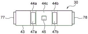
As shown in fig. 6 and 7A, the surface texture measuring apparatus 30 includes a housing 43. The housing 43 houses therein a measurement structure for measuring the surface properties of the polishing pad 2. The measurement structure housed inside the housing 43 is, for example, the light source 31, the light receiving unit 33, the polarizer 35, the ND filter 36, the reflecting mirror 37, the band pass filter 38, the imaging device 39, and the like described with reference to fig. 3 to 5.
As shown in fig. 7A, a notch 44 is formed in the lower portion of the housing 43. The notch 44 of the present embodiment has a trapezoidal shape, and is defined by 2 inclined surfaces 44a and 44b facing each other and a connection surface 44c connecting the inclined surfaces 44a and 44 b. As shown in fig. 7B, a light-transmitting filter 47a is disposed on one of the inclined surfaces 44a, and the polishing pad 2 is irradiated with the laser beam emitted from the light source 31 through the filter 47 a. A light-transmitting filter 47b is also disposed on the other inclined surface 44b, and the light receiving unit 33 receives the reflected light from the polishing pad 2 through the filter 47b. Examples of the filters 47a and 47b include a transparent film and a transparent glass. The connection surface 44c of the present embodiment extends linearly from the one inclined surface 44a to the other inclined surface 44 b.
The surface texture measuring apparatus 30 includes positioning plates 77 and 78 fixed to the side surfaces of the housing 43. When the surface texture measuring apparatus 30 is moved to the measurement position (described later) shown in fig. 6 and 7A, the positioning plates 77 and 78 are brought into contact with the polishing surface 2a of the polishing pad 2. The distance from the polishing surface 2a of the polishing pad 2 in the vertical direction to the measurement structure of the surface texture measuring apparatus 30 and the normal angle of the surface texture measuring apparatus 30 with respect to the polishing surface 2a can be kept constant by the positioning plates 77 and 78.
As shown in fig. 7A, 7B, and 8, the surface texture measuring apparatus 30 may include a nozzle 45 having a tip projecting from the connection surface 44 c. The nozzle 45 of the surface texture measuring apparatus 30 is connected to a pressurized gas supply line (not shown) and configured to blow pressurized gas (e.g., pressurized nitrogen gas or pressurized air) from the pressurized gas supply line to the polishing surface 2a of the polishing pad 2. The polishing liquid or liquid such as dressing liquid on the polishing surface 2a is removed by the pressurized gas blown from the nozzle 45. Thus, the surface texture measuring device 30 can measure the surface texture of the polishing pad 2 accurately.
The nozzle 45 has an arbitrary shape. For example, the nozzle 45 may be a cylindrical nozzle having the same flow path diameter from the front end to the rear end, or may be a Laval (Laval) nozzle having a throat portion in which the flow path diameter is gradually reduced; and an enlarged portion having a diameter gradually enlarged downstream of the throat portion. Alternatively, the nozzle 45 may have a shape in which the diameter of the flow path gradually decreases or increases toward the tip of the nozzle 45.
As shown in fig. 8, the nozzle 45 is disposed obliquely to the polishing surface 2a of the polishing pad 2, and the pressurized gas ejected from the nozzle 45 obliquely impinges on the polishing surface 2a of the polishing pad 2. The nozzle 45 is disposed to be inclined at an inclination angle θ with respect to a plane P parallel to the polishing surface 2a of the polishing pad 2, and allows the pressurized gas to flow toward the opening of the notch 44 formed in the housing 43. With this configuration, the liquid removed by the pressurized gas ejected from the nozzle 45 is prevented from adhering to the filters 47a and 47b disposed on the inclined surfaces 44a and 44b of the notch 44, respectively.
The purpose of jetting the pressurized gas from the inclined nozzle 45 in this manner is to remove the liquid such as the polishing liquid or the dressing liquid on the polishing surface 2a and to prevent the liquid removed by the pressurized gas from scattering and adhering to the filters 47a and 47b. Therefore, the inclination angle θ of the nozzle 45 is set to an optimum inclination angle for achieving the above-described object. The optimum inclination angle is determined, for example, according to the pressure, flow rate, and the like of the pressurized gas ejected from the nozzle 45. The optimum tilt angle may also be determined experimentally by varying the pressure and/or flow rate of the pressurized gas. The optimum inclination angle is, for example, 60 °. The nozzle 45 may also be rotatably mounted relative to the housing 43 in one embodiment. At this time, the inclination angle θ of the nozzle 45 can be changed to an optimum inclination angle according to the pressure and flow rate of the pressurized gas.
Fig. 9 is an enlarged schematic view of the periphery of the surface texture measuring apparatus 30 shown in fig. 6. As shown in fig. 6 and 9, the surface texture measuring apparatus 30 for measuring the surface texture of the polishing pad 2 is supported by a support arm 50, and the support arm 50 is connected to a moving means 53 fixed to the polishing apparatus. The moving means 53 is a means for moving the surface texture measuring apparatus 30 from the standby position to the measuring position or from the measuring position to the standby position. That is, the position of the surface texture measuring apparatus 30 is automatically changed from the standby position to the measuring position or from the measuring position to the standby position by the moving means 53.
In the present embodiment, the measurement position of the surface texture measuring device 30 is defined as a position where the surface texture measuring device 30 comes into contact with the polishing pad 2 in order to measure the surface texture of the polishing pad 2. For example, as shown in fig. 7A, the measurement position of the surface texture measuring apparatus 30 is the position where the positioning plates 77 and 78 of the surface texture measuring apparatus 30 are in contact with the polishing surface 2a of the polishing pad 2. The standby position of the surface texture measuring apparatus 30 is defined as a position where the surface texture measuring apparatus 30 is separated from the polishing pad 2.
As shown in fig. 9, the moving unit 53 is composed of a fixed block 55 fixed to the grinding apparatus; a rotating block 56 coupled to the support arm 50; a rotating shaft 58 rotatably connected to the rotating block 56 with respect to the fixed block 55; and a turning mechanism 60 for turning the turning block 56 around the axis of the rotary shaft 58. The fixing block 55 is fixed to the frame 48 of the polishing apparatus by a fixing tool (not shown) such as a screw. The support arm 50 supporting the surface texture measuring apparatus 30 is connected to a support plate 52 fixed to the turning block 56 by a fixing tool (not shown) such as a screw, and is connected to the turning block 56 via the support plate 52. In one embodiment, the support plate 52 may be formed integrally with the rotation block 56. Alternatively, support arm 50 may be directly connected to rotating block 56. At this time, the support plate 52 is omitted from the moving unit 53.
The rotating block 56 is coupled to the fixed block 55 via a rotating shaft 58. More specifically, a concave portion 55a is formed in the fixed block 55, and a convex portion 56a inserted into the concave portion 55a of the fixed block 55 is formed in the rotating block 56. The protruding portion 56a has a through hole (not shown) into which the rotary shaft 58 is inserted. The fixing block 55 has 2 through holes (not shown) formed on both sides of the recess 55a of the fixing block 55. When the protrusion 56a of the rotary block 56 is inserted into the recess 55a of the fixed block 55, 2 through holes formed in the fixed block 55 and 2 through holes formed in the protrusion 56a of the rotary block 56 can be aligned in a straight line. In a state where the convex portion 56a of the rotating block 56 is inserted into the concave portion 55a of the fixed block 55, the rotating shaft 58 is inserted into 2 through holes formed in both side portions of the concave portion 55a of the fixed block 55 and the through holes formed in the convex portion 56a. Thereby, the rotating block 56 is rotatably connected to the fixed block 55.
Fig. 10 is a view showing the surface texture measuring apparatus 30 moved to the measurement position by the rotating mechanism 60 shown in fig. 9, and fig. 11 is a view showing the surface texture measuring apparatus 30 moved to the standby position by the rotating mechanism 60 shown in fig. 9.
As shown in fig. 10 and 11, the pivoting mechanism 60 of the present embodiment is a piston-cylinder mechanism including a piston 62 connected to the pivoting block 56 and a cylinder 63 accommodating the piston 62 to be movable forward and backward. The front end of the piston 62 is coupled to the rotary block 56 via a bracket 70 fixed to the lower surface of the rotary block 56. A through hole (not shown) into which the plug 67 can be inserted is formed at the tip of the piston 62, and a through hole 68 into which a plug 72 inserted into the through hole of the piston 62 can be inserted is formed in the bracket 70. In a state where the through-hole formed at the tip of the piston 62 and the through-hole 68 of the bracket are aligned in line, the piston 62 is coupled to the rotary block 56 via the bracket 70 by inserting the pin 67 into the through-hole of the piston 62 and the through-hole 68 of the bracket. The bracket 70 fixed to the lower surface of the rotating block 56 is rotatably coupled to the piston 62.
The cylinder 63 is supported by a table 49 extending from the frame 48 of the grinding apparatus. A fluid supply line (not shown) is connected to the cylinder 63, and a fluid (e.g., pressurized nitrogen gas or pressurized air) is supplied to the cylinder 63 through the fluid supply line. The controller 23 (see fig. 1) controls the fluid supplied to the cylinder 63 to move the piston 62 up and down. For example, an on-off valve (not shown) is disposed in the fluid supply line, and the piston 62 is moved up and down by the control unit 23 controlling the operation of the on-off valve. More specifically, when the piston 62 is raised, the control unit 23 opens the on-off valve to supply the fluid to the cylinder 63. When the piston 62 is lowered, the control unit 23 closes the on-off valve to stop the supply of the fluid to the cylinder 63.
When measuring the surface properties of the polishing pad 2, the controller 23 lowers the piston 62 of the rotating mechanism 60. Thereby, the rotating block 56 and the support arm 50 are rotated in the direction in which the surface texture measuring apparatus 30 is moved downward, and the positioning plates 77 and 78 of the surface texture measuring apparatus 30 are brought into contact with the polishing pad 2. In this manner, the control unit 23 can move the surface texture measuring apparatus 30 to the measurement position shown in fig. 10 by operating the rotating mechanism 60. In this state, the surface properties of the polishing pad 2 were measured, and conditioning conditions were determined. When the control unit 23 detects an abnormality of the polishing pad 2 from the measured value of the surface texture obtained by the surface texture measuring device 30, the control unit 23 may notify the abnormality and stop the operation of the polishing device.
When the measurement of the surface properties of the polishing pad 2 is completed and the dressing condition is determined, the control unit 23 raises the piston 62 of the rotating mechanism 60. Thereby, the turning block 56 and the support arm 50 are turned in a direction in which the surface texture measuring device 30 is moved upward, and the surface texture measuring device 30 is separated from the polishing pad 2 (see fig. 11). In this manner, the control unit 23 moves the surface texture measuring apparatus 30 from the measurement position shown in fig. 10 to the retreat position shown in fig. 11 by operating the rotating mechanism 60. When the surface texture of the polishing pad 2 is measured again, the control unit 23 moves the surface texture measuring apparatus 30 from the standby position shown in fig. 11 to the measurement position shown in fig. 10 by operating the rotating mechanism 60.
Fig. 12 is a schematic view showing another example of the turning mechanism. The turning mechanism 60 shown in fig. 12 includes a motor 59 coupled to the rotating shaft 58, and the motor 59 is electrically connected to the control unit 23. The motor 59 is supported by a table 49 extending from the frame 48 of the grinding apparatus. The rotary shaft 58 of the present embodiment is fixed to the turning block 56. For example, the rotary shaft 58 has a key, not shown, and a key groove for engaging with the key is formed in the convex portion 56a of the rotating block 56. The rotary shaft 58 is fixed to the turning block 56 by the keys engaging with the keyways by inserting the keys of the rotary shaft 58 into the keyways of the turning block 56.
The control unit 23 controls the operation of the motor 59 to rotate the rotary shaft 58, thereby rotating the rotary block 56 relative to the fixed block 55. Since the turning block 56 is connected to the support arm 50 and the surface texture measuring device 30 via the support plate 52, the surface texture measuring device 30 can be moved from the standby position (see fig. 11) to the measurement position (see fig. 10) or vice versa by the operation of the motor 59.
As shown in fig. 9, the turning block 56 may be constituted by a first plate 64 connected to the support arm 50 via the support plate 52 and a second plate 65 connected to the fixed block 55 via the rotary shaft 58. The first plate 64 is rotatably connected to the second plate 65 via a rotating pin 66. The first plate 64 of the embodiment shown in fig. 9 is coupled to the second plate 65 by a hinge mechanism 88 including a rotation pin 66. The hinge mechanism 88 is comprised of a first joint 89 secured to the upper surface of the first plate 64; a second joint 90 fixed to the second plate 65; and a rotation pin 66 for rotatably connecting the first joint 89 to the second joint 90.
Fig. 13 is a schematic view showing a state in which the surface texture measuring apparatus 30 is moved to the maintenance position. The maintenance position is a position at which the surface texture measuring apparatus 30 is separated from the polishing pad 2 in order to maintain or replace the polishing pad 2. In the example shown in fig. 13, the hinge mechanism 88 is operated to extend the support arm 50 in the vertical direction. Thus, the surface texture measuring device 30 is located at a position away from the polishing pad 2, and therefore, the polishing pad 2 can be easily repaired or replaced.
Although not shown, the polishing apparatus preferably includes a fixture for preventing the movement of the support arm 50 when the surface texture measuring apparatus 30 is moved to the maintenance position. The support arm 50 moved to the maintenance position is prevented from being inadvertently dropped by the fixing tool. As an example of the fixture, a hook or a clip engageable with the support arm 50 moved to the maintenance position is exemplified.
In the present embodiment, the control unit 23 controls the operation of the rotating mechanism 60 of the moving means 53 to move the surface texture measuring device 30 from the standby position to the measurement position, and the surface texture measuring device 30 is further used to automatically acquire the surface texture of the polishing pad 2. The control unit 23 determines the dressing condition based on the obtained surface properties. The control unit 23 may notify an abnormality based on the acquired surface property. In this way, since it is not necessary to perform the attachment/detachment work of the surface texture measuring apparatus which has been required in the past, the yield of the polishing apparatus can be improved, and the burden on the operator can be reduced.
The polishing apparatus may have a posture adjusting mechanism for automatically adjusting the posture of the surface texture measuring apparatus 30, and when the surface texture measuring apparatus 30 is moved to the measurement position, the lower surface of the surface texture measuring apparatus 30 may be parallel to the surface of the polishing pad 2.
Fig. 14A is a schematic front view of a posture adjustment mechanism according to an embodiment, and fig. 14B is a view seen in a direction of an arrow B-B of fig. 14A. Fig. 15A is a sectional view taken along line C-C in fig. 14A, and fig. 15B is a partial sectional view of the attitude adjusting mechanism corresponding to fig. 15A when the surface texture measuring apparatus 30 is moved to the standby position.
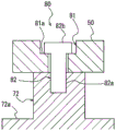
As shown in fig. 14A and 14B, the posture adjustment mechanism 70 includes: a support base 72 connected to the support arm 50; and at least one adjusting pin 73 fixed to the upper surface of the surface texture measuring apparatus 30 and extending through a through hole formed in the support base 72. In the present embodiment, 4 adjustment pins 73 are fixed to the upper surface of the surface texture measuring apparatus 30. Support table 72 is directly fixed to the lower surface of support arm 50. The support base 72 has a flange portion 72a at its lower portion, and 4 through holes 74 are formed at 4 corners of the flange portion 72 a. The adjustment pins 73 extend through-holes 74 formed in the flange portion 72a of the support base 72.
As shown in fig. 15A, the adjustment pin 73 includes: a pin main body 73a having a diameter Da smaller than the diameter Dp of the through hole 74; and a pin head 73b formed at an upper portion of the pin body 73 a. The pin head 73b is located above the through hole 74. More specifically, the pin head 73b is positioned between the support arm 50 and the flange portion 72a of the support base 72 (see fig. 14A). The pin head 73b has a diameter Db larger than the diameter Dp of the through hole 74.
As shown in fig. 15B, when the control unit 23 moves the surface texture measuring device 30 to the standby position, the lower surface of the pin head 73B contacts the upper surface of the flange portion 72a of the support base 72, and thereby the surface texture measuring device 30 is supported by the support arm 50 via the support base 72. The controller 23 moves the surface texture measuring device 30 to the measuring position, and when the positioning plates 77 and 78 of the surface texture measuring device 30 are brought into contact with the polishing surface 2a of the polishing pad 2, the lower surface of the pin head 73b is separated from the flange portion 72a of the support base 72. Thereby, the surface texture measuring device 30 is supported by its own weight on the polishing surface 2a of the polishing pad 2. Therefore, the posture of the surface texture measuring apparatus 30 is adjusted by the posture adjustment mechanism 70 so that the lower surface thereof is parallel to the polishing surface 2a of the polishing pad 2.
As shown in fig. 9, the polishing apparatus may further include a displacement mechanism 80 for adjusting the horizontal position of the surface texture measuring apparatus 30 along the support arm 50. The displacement mechanism 80 is a mechanism for moving the horizontal position of the surface texture measuring apparatus 30 along the longitudinal direction of the support arm 50.
Fig. 16 is a perspective view schematically showing the shift mechanism 80 shown in fig. 9. Fig. 17 is a cross-sectional view taken along line D-D of fig. 16. As shown in fig. 16 and 17, the shift mechanism 80 includes: a long hole 81 extending along the longitudinal direction of support arm 50; and a support shaft 82 inserted into the elongated hole 81. A step 81a is formed inside the elongated hole 81. The support shaft 82 has: a shaft main body 82a connected to the surface texture measuring device 30; and a stub 82b in contact with the stepped portion 81a of the elongated hole 81. The support shaft 82 of the present embodiment is screwed into a bolt formed in a screw hole (not shown) formed in the upper surface of the support base 72, and is connected to the surface texture measuring apparatus 30 via the support base 72 and the posture adjusting mechanism 70. In the following description, the support shaft 82 is referred to as a bolt 82, the shaft body 82a is referred to as a bolt body 82a, and the spindle head 82b is referred to as a bolt head 82b.
The bolt body 82a of the bolt 82 has a diameter smaller than the width of the step portion 81a in the horizontal direction in the direction perpendicular to the longitudinal direction of the long hole 81, and the bolt head 82b of the bolt 82 has a diameter larger than the width of the step portion 81a of the long hole 81. The diameter of the bolt head 82b is smaller than the width of the upper part of the long hole 81 where the step 81a is not formed. Therefore, when bolt 82 is inserted into elongated hole 81 from above support arm 50, bolt main body 82a can pass through elongated hole 81 without contacting step 81a of elongated hole 81. The bolt head 82b contacts the stepped portion 81a of the elongated hole 81 and cannot pass through the stepped portion 81a.
When surface texture measuring device 30 is supported by support arm 50, bolt 82 is inserted into elongated hole 81 from above support arm 50 in a state where support base 72 is in contact with the lower surface of support arm 50, and is screwed into a screw hole formed in support base 72. Surface property measuring device 30 is coupled to support arm 50 via support base 72 by screwing bolt 82 into the screw hole of support base 72 until bolt head 82b of bolt 82 comes into contact with step 81a. By further screwing the bolt 82 into the screw hole of the support base 72, the support base 72 is firmly fixed to the support arm 50 by the bolt 82, thereby fixing the horizontal position of the support base 72 (i.e., the surface texture measuring device 30).
When the horizontal position of the surface texture measuring device 30 is adjusted (i.e., changed), the bolts 82 are loosened to move the support base 72 (i.e., the surface texture measuring device 30) to a desired position along the elongated hole 81. Then, the bolt 82 is screwed into the screw hole of the support base 72 again to fix the horizontal position of the surface texture measuring apparatus 30.
In the case of this embodiment, since the horizontal position of the surface texture measuring apparatus 30 can be adjusted by the displacement mechanism 80, the surface texture measuring apparatus 30 can measure the surface texture at an arbitrary position (that is, a desired position) of the polishing pad 2.
Fig. 18 is a schematic diagram showing another embodiment of the displacement mechanism 80. The configuration of the present embodiment, which is not described in particular, is the same as the configuration of the shift mechanism 80 shown in fig. 16 and 17, and therefore, redundant description thereof is omitted.
In the shift mechanism 80 of fig. 18, the position of the support base 72 is not fixed to the support arm 50 by the support shaft (bolt) 82. More specifically, the stub 82b of the support shaft 82 only contacts the stepped portion 81a, and the elongated hole 81 functions as a guide hole for moving the support base 72 (i.e., the surface texture measuring device 30) along the support arm 50. The displacement mechanism 80 further includes a piston cylinder mechanism 83 having: a piston 85 connected to the surface texture measuring device 30; and a cylinder 86 for housing the piston 85 to be movable forward and backward. In the present embodiment, the front end of piston 85 is connected to the side surface of support base 72, and cylinder 86 is fixed to the lower surface of support arm 50. The cylinder 86 is connected to a fluid supply line, not shown.
Although not shown, the displacement mechanism 80 may have a ball screw mechanism for changing the position of the surface texture measuring apparatus 30 in the horizontal direction, instead of the piston cylinder mechanism 83. Even in this case, the horizontal position of the surface texture measuring apparatus 30 can be automatically adjusted by controlling the operation of the ball screw mechanism by the control unit 23.
The control unit 23 may measure the surface properties of the rotating polishing pad 2 by moving the surface property measuring device 30 to the measuring position (see fig. 10) during polishing of the substrate W or during dressing of the polishing pad 2. As described above, the surface texture measuring apparatus 30 includes the filters 47a and 47B (see fig. 7B) disposed on the inclined surfaces 44a and 44B of the housing 43, respectively. During polishing or dressing of the substrate W, a fluid such as a polishing liquid (slurry) or a dressing liquid is supplied to the polishing pad 2, but the fluid is prevented from entering the inside of the housing 43 by the filters 47a and 47b. Therefore, the measurement structures such as the light source 31 and the light receiving unit 33 can be prevented from being contaminated by the fluid by the filters 47a and 47b. When the surface texture measuring apparatus 30 includes the nozzle 45 (see fig. 8) disposed obliquely with respect to the polishing surface 2a of the polishing pad 2, the fluid on the polishing surface 2a is blown out of the surface texture measuring apparatus 30 from the notch 44 by the pressurized gas jetted from the nozzle 45. As a result, even during polishing or dressing of the substrate W, the adhesion of the fluid to the filters 47a and 47b can be more effectively prevented, and the surface properties of the polishing pad 2 can be accurately measured.
Fig. 19 is a schematic diagram showing an example of the internal structure (measurement structure) of the imaging device 39 shown in fig. 5. Fig. 19 also shows a part of a housing 43 of the surface texture measuring apparatus 30 that houses the imaging device 39. A part of the housing 43 shown in fig. 19 shows a modification of the notch 44 formed in the lower part of the housing 43 for accommodating the imaging device 39.
As described above, the imaging device 39 is housed in the housing 43 of the surface texture measuring apparatus 30, and acquires image information of the surface texture of the polishing pad 2. The imaging device 39 shown in fig. 19 includes: an image sensor having a photographing surface 39 a; a lens mechanism 24 for forming an image of the surface of the polishing pad 2 on the imaging surface 39 a; and a diaphragm 29. The lens mechanism 24 includes: a lens 25; and a focusing mechanism (not shown) for moving the lens 25 between the surface of the polishing pad 2 and the imaging surface 39 a. The lens 25 is moved by the focusing mechanism, and the surface image of the polishing pad 2 is formed on the image pickup surface 39 a.
In the present embodiment, the diaphragm 29 is disposed between the imaging surface 39a and the lens 25. The aperture 29 is used to adjust the size of the field of view of the imaging device 39 and to remove noise from the background.
Although not shown, the surface texture measuring apparatus 30 shown in fig. 3 and 4 may be provided with a diaphragm 29. At this time, the diaphragm 29 is disposed between the polishing surface 2a and the light receiving portion 33 on the optical path formed between the light projecting portion 32 and the light receiving portion 33. The aperture 29 is used for adjusting the diffraction width (the order of diffracted light) of the laser light reflected from the polishing pad 2 and for removing noise from the background.
The notch 44 formed in the lower portion of the housing 43 of the surface texture measuring apparatus 30 in the present embodiment has the following shape: this shape is defined by 2 opposing inclined faces 44a, 44b; side surfaces 44d, 44e extending upward from the inclined surfaces 44a, 44b; and a connection surface 44c connecting the side surfaces 44d and 44e. The side faces 44d, 44e of the illustrated example extend in the vertical direction. The following description refers to the side surfaces 44d and 44e as vertical surfaces 44d and 44e, respectively.
When the liquid such as the polishing liquid or the dressing liquid is present on the polishing surface 2a of the polishing pad 2 imaged by the imaging device 39, the imaging device 39 cannot acquire accurate surface property image information of the polishing pad 2. Therefore, the pressurized gas is ejected from the nozzle 45 to remove the liquid on the polishing surface 2a imaged by the imaging device 39.
In the present embodiment, the nozzle 45 protrudes from one inclined surface 44 a. The opening 27 is formed in one vertical surface 44d, and the other opening 28 is formed in the other vertical surface 44e. The openings 27, 28 are located between the abrasive surface 2a and the lens 25. The opening 27 is configured to eject a gas (e.g., CDA (clean dry air), dry air, nitrogen gas, etc.) toward the opening 28, and the opening 28 is configured to allow the gas ejected from the opening 27 to flow in. By so constituting, a gas curtain from the opening 27 toward the opening 28 can be formed. The liquid scattered by the pressurized gas ejected from the nozzle 45 is prevented from reaching the lens 25 by the gas curtain formed between the openings 27 and 28. Therefore, the image pickup device 39 can obtain accurate image information of the polishing surface 2a of the polishing pad 2.
In the example shown in fig. 19, the opening 27 is parallel to the sheet of fig. 19 and is located on a vertical plane passing through the nozzle 45, and the gas from the opening 27 and the pressurized gas from the nozzle 45 are ejected in a direction parallel to the sheet of fig. 19. However, the opening 27 may be parallel to the paper surface of fig. 19 and may be shifted from the vertical plane passing through the nozzle 45 to the horizontal direction. Further, the gas from the opening 27 and/or the pressurized gas from the nozzle 45 may be ejected in a direction different from the direction parallel to the paper surface of fig. 19.
Although not shown, a part (for example, a lower part) of the inclined surface 44b facing the nozzle 45 may be formed into a curved surface. A part of the surface of the inclined surface 44b formed into a curved surface functions as a guide surface for smoothly discharging the liquid discharged from the polishing surface 2a by the pressurized gas ejected from the nozzle 45 to the outside of the housing 43 of the surface texture measuring apparatus 30. Alternatively, a notch for easily discharging the liquid to the outside of the housing 43 may be provided at a lower portion of the inclined surface 44b facing the nozzle 45.
FIG. 20 is a schematic view showing another embodiment of the surface texture measuring apparatus 30. The configuration of the present embodiment, which is not described in particular, is the same as the configuration of the surface texture measuring apparatus 30 of the above-described embodiment, and therefore, redundant description is omitted.
As shown in fig. 20, the surface texture measuring apparatus 30 includes a barrier layer 69 connected to a side surface of the case 43. In the present embodiment, the stopper 69 is attached to the side surface of the positioning plate 78. When the surface texture measuring apparatus 30 is moved to the measurement position (see fig. 10), the lower surface of the stopper layer 69 contacts the polishing surface 2a of the polishing pad 2. The barrier layer 69 functions as a barrier for preventing a fluid such as a polishing liquid or a dressing liquid supplied to the polishing surface 2a of the polishing pad 2 from reaching the surface texture measuring apparatus 30. The barrier layer 69 of the present embodiment has an arc shape, and guides the fluid flowing on the polishing surface 2a toward the surface texture measuring device 30 along the arc shape of the barrier layer 69, thereby preventing the liquid from reaching the surface texture measuring device 30. Although not shown, barrier 69 may be attached to support arm 50.
Fig. 21 is a schematic view showing a polishing apparatus according to still another embodiment. Fig. 22 is a schematic view showing the dresser shown in fig. 21 in an enlarged manner, and fig. 23 is a plan view schematically showing a state in which the dresser shown in fig. 21 is swung on the polishing pad. The configuration of the present embodiment, which is not particularly described, is the same as the configuration of the above-described embodiment, and the same or corresponding members are denoted by the same reference numerals, and redundant description thereof is omitted.
The polishing apparatus shown in fig. 21 includes a polishing unit constituted by a polishing table 1 to which a polishing pad 2 is bonded, a carrier 10, and the like, and a dressing apparatus 20, as in the polishing apparatus shown in fig. 1. The finisher 20 shown in fig. 21 includes: a dresser arm 21; dresser 22 rotatably attached to dresser arm 21; dresser shaft 91 coupled to dresser 22; and a cylinder 93 provided at the upper end of the dresser shaft 91. The dresser shaft 91 is rotatably supported by the dresser arm 21, and is rotated by a motor (not shown) disposed in the dresser arm 21. The dresser 22 is rotated around its axial center by the rotation of the dresser shaft 91. In the present embodiment, dressing member 22a provided in a lower portion of dresser 22 has a ring shape, but dressing member 22a may have a circular shape.
Further, the dressing apparatus 20 includes: a support shaft 98 connected to the dresser arm 21; and a motor (rotary actuator) 96 for rotating the support shaft 98. The dresser arm 21 is configured to be driven by a motor 96 and to swing about a support shaft 98.
The dressing of the polishing surface 2a of the polishing pad 2 is performed as follows. The polishing table 1 and the polishing pad 2 are rotated by a rotation motor (not shown) of the polishing table, and a conditioning liquid (for example, deionized water) is supplied from a conditioning liquid supply nozzle (not shown) to the polishing surface 2a of the polishing pad 2. Further, dresser 22 is rotated about its axis. The dresser 22 is pressed against the polishing surface 2a by the air cylinder 93, and the lower surface of the dresser member 22a is brought into sliding contact with the polishing surface 2a. In this state, the dresser arm 21 is swung to move the dresser 22 on the polishing pad 2 in the approximate radial direction of the polishing pad 2. As shown in fig. 23, the polishing table 1 and the polishing pad 2 thereon rotate with the origin (center point of the polishing pad 2) O as the center. On the other hand, dresser 22 rotates (i.e., swings) by a predetermined angle about a point C corresponding to the center position of support shaft 98 shown in fig. 21. The polishing pad 2 is shaved by the rotating dresser 22, thereby dressing the polishing surface 2a.
As shown in fig. 21 and 22, the polishing apparatus includes a surface texture measuring device 30 attached to the dresser 22. Surface texture measuring apparatus 30 shown in fig. 22 is fixed to the tip of sub-arm 95 attached to the outer peripheral surface of dresser 22. The sub-arm 95 has a substantially L-shaped cross-sectional shape, and the surface texture measuring device 30 is fixed to the tip of the sub-arm 95. The tip of sub-arm 95 is fixed to the outer peripheral surface of dresser 22. The support arm that supports the surface texture measuring device 30 in the present embodiment is the dresser arm 21, and the surface texture measuring device 30 is supported by the dresser arm 21 via the sub-arm 95, the dresser 22, and the dresser shaft 91.
The surface texture measuring apparatus 30 shown in fig. 22 may have the internal structure (measurement structure) described with reference to fig. 3 or 4, or may have the imaging apparatus 39 described with reference to fig. 5 and 19. The internal configuration described below with reference to fig. 3 or 4 will be simply referred to as "the above-described measurement configuration". The surface texture measuring apparatus 30 may have a housing 43 for housing the measuring structure or the imaging device 39. The shape of the housing 43 is arbitrary, but for example, the housing 43 described with reference to fig. 7A and 7B may be used. Or the housing 43 may have a cylindrical shape.
In one embodiment, the surface texture measuring device 30 may be housed inside the sub-arm 95. In this case, the measurement structure or the imaging device 39 is disposed in the sub-arm 95, and an opening is formed at the tip of the sub-arm 95. When the surface texture measuring apparatus 30 has the above-described measurement structure, the laser light projected from the light projecting section 32 reaches the surface of the polishing pad 2 through the opening formed in the sub-arm 95, and the reflected light reflected by the surface of the polishing pad 2 is received by the light receiving section 33 through the opening formed in the sub-arm 95. When the surface texture measuring apparatus 30 includes the imaging device 39, the imaging device 39 acquires image information of the surface of the polishing pad 2 through the opening formed in the sub-arm 95.
The surface texture measuring apparatus 30 may further include the nozzle 45 described with reference to fig. 8. As described above, the nozzle 45 is configured to blow a pressurized gas (e.g., pressurized nitrogen gas or pressurized air) onto the polishing surface 2a of the polishing pad 2. And a liquid such as a polishing liquid or a dressing liquid on the polishing surface 2a is removed by the pressurized gas blown from the nozzle 45. Although not shown, a pressurized gas supply line for supplying pressurized gas to the nozzle 45 is connected to the dresser shaft 91 via, for example, a rotary joint, and is supplied to the surface texture measuring apparatus 30 via the dresser shaft 91, the dresser 22, and a flow path formed inside the sub-arm 95.
As shown in fig. 22, the surface texture measuring apparatus 30 is separated from the polishing surface 2a of the polishing pad 2 when the dressing member 22a of the dresser 22 is brought into contact with the polishing surface 2a. The position of the surface texture measuring device 30 when the dressing member 22a of the dresser 22 of the present embodiment contacts the polishing surface 2a of the polishing pad 2 is the above-described measurement position. Since the surface texture measuring device 30 is fixed to the tip of the sub-arm 95, the distance between the surface texture measuring device 30 and the polishing surface 2a of the polishing pad 2 at the measurement position is always constant. Therefore, the surface texture measuring device 30 can measure the accurate pad surface texture of the polishing surface 2a of the polishing pad 2.
As described above, the dresser 22 can be moved above the polishing surface 2a of the polishing pad 2 by the air cylinder (lift actuator) 93. In the present embodiment, the position at which the dressing member 22a of the dresser 22 is spaced upward from the polishing surface 2a of the polishing pad 2 is the standby position, and the moving mechanism for moving the surface texture measuring device 30 from the measuring position to the standby position is the air cylinder 93. In one embodiment, after dresser 22 and surface texture measuring device 30 are moved upward from polishing surface 2a of polishing pad 2 by air cylinder 93, dresser 22 and surface texture measuring device 30 may be moved to the side of polishing pad 2 by motor (rotary actuator) 96 (see dresser 22 shown by the two-dot chain line in fig. 23). In this case, the standby position of the surface texture measuring apparatus 30 is a position on the side of the polishing pad 2, and the moving mechanism is constituted by a combination of the air cylinder 93 and the motor 96.
Although not shown, when the dressing member 22a of the dresser 22 is brought into contact with the polishing surface 2a of the polishing pad 2, the surface texture measuring device 30 may be brought into contact with the polishing surface 2a. At this time, the position where the surface texture measuring device 30 contacts the polishing pad 2 is the measurement position of the surface texture measuring device 30. The surface texture measuring apparatus 30 is preferably connected to the sub-arm 95 via the posture adjustment mechanism 70 described with reference to fig. 14A and 14B. The posture of the surface texture measuring apparatus 30 in contact with the polishing surface 2a is adjusted by the posture adjusting mechanism 70 so that the lower surface thereof is parallel to the polishing surface 2a of the polishing pad 2. At this time, the retreat position of the surface texture measuring device 30 is a position where the surface texture measuring device 30 is separated from the polishing surface 2a of the polishing pad 2, or a position where the dresser 22 and the surface texture measuring device 30 are moved to the side of the polishing pad 2.
The measurement of the pad surface texture by the surface texture measuring device 30 may be performed by moving the surface texture measuring device 30 to the measurement position during the polishing of the substrate W or the dressing of the polishing pad 2. At this time, the surface texture measuring device 30 rotates together with the dresser 22, and measures the surface texture of the polishing pad 2.
As shown in fig. 21, the polishing apparatus includes a rotary encoder 92 capable of measuring the rotation angle of the dresser 22 via a dresser shaft 91. The relative position of the rotating surface texture measuring device 30 with respect to the polishing pad 2 can be detected by the rotary encoder 92. More specifically, in dressing of the polishing pad 2, the surface texture measuring device 30 rotates together with the dresser 22. At this time, the surface texture measuring device 30 alternately passes over the polishing pad 2 before dressing with the dresser 22 and over the polishing pad 2 after dressing with the dresser 22. The surface texture measuring device 30 measures the surface texture of the polishing pad 2 at predetermined time intervals, and transmits the measured value to the control unit 23 (see fig. 1) every time the surface texture of the polishing pad 2 is measured.
The rotary encoder 92 is also connected to the control unit 23, and the rotary encoder 92 transmits the relative position of the surface texture measuring apparatus 30 with respect to the polishing pad 2 to the control unit 23. The control unit 23 divides the plurality of pad surface property values obtained by the surface property measurement device 30 into the pad surface property value before dressing and the pad surface property value after dressing, based on the transmitted relative positions. Then, the control unit 23 compares the pad surface property value after dressing with the pad surface property value before dressing, and calculates an appropriate dressing condition based on the comparison. For example, the dressing conditions are calculated so that the difference in the pad surface property values before and after dressing is within a predetermined range. At this time, the control unit 23 obtains a relational expression indicating the difference between the dressing condition and the pad surface property value before and after dressing in advance, and obtains an appropriate dressing condition from the relational expression.
In one embodiment, the position of the surface texture measuring apparatus 30 when the dressing member 22a is spaced upward from the surface of the polishing pad 2 may be set as the measurement position. At this time, the retreat position of the surface texture measuring apparatus 30 is a position of the surface texture measuring apparatus 30 when the dressing member 22a is further separated upward from the surface of the polishing pad 2, or a position where the dresser 22 and the surface texture measuring apparatus 30 are moved to the side of the polishing pad 2. In the present embodiment, in a state where the dressing member 22a and the surface texture measuring device 30 are separated from the surface of the polishing pad 2, the dresser 22 is not rotated but moved from the peripheral portion to the central portion of the polishing pad 2 via the dresser arm 21. When the surface texture measuring device 30 moves together with the dresser 22 from the peripheral portion to the central portion of the polishing pad 2, the surface texture of the polishing pad 2 is measured at predetermined time intervals, and the measured value is transmitted to the control unit 23. The control unit 23 calculates appropriate dressing conditions based on the pad surface property values transmitted from the surface property measurement device 30.
Fig. 24A is a schematic view showing a modification of the dresser of the polishing apparatus shown in fig. 21, and fig. 24B is a top view of the dresser shown in fig. 24A. Since the configuration of the present embodiment, which is not described in particular, is the same as the configuration of dresser 22 shown in fig. 21, redundant description thereof will be omitted.
A plurality of surface texture measuring devices 30A and 30B (example 2 shown in the figure) are attached to dresser 22 of the polishing apparatus shown in fig. 24A and 24B. Surface texture measuring devices 30A and 30B are arranged symmetrically with respect to the center of dresser 22. Sub-arm 95 connecting each surface texture measuring device 30 to dresser 22 has a substantially J-shaped configuration, and the tip of sub-arm 95 is fixed to the upper surface of dresser 22.
In the present embodiment, 2 surface texture measuring devices 30A and 30B are attached to dresser 22, but 3 or more surface texture measuring devices may be attached to dresser 22. For example, 4 surface texture measuring devices may be arranged at 90 ° intervals along the outer peripheral surface of dresser 22. In the following description, the surface texture measuring apparatuses 30A and 30B are simply referred to as "surface texture measuring apparatus 30" unless otherwise specified.
The surface texture measuring apparatuses 30 may have the same measuring structure or may have different measuring structures. For example, some of the surface texture measuring devices 30 (for example, the surface texture measuring device 30A) have the surface texture measuring device having the measuring structure described with reference to fig. 3 or 4, while the remaining surface texture measuring devices (for example, the surface texture measuring device 30B) have the surface texture measuring device having the imaging device 39 described with reference to fig. 5 and 19.
As in the above-described embodiment, in dressing the polishing pad 2, the plurality of surface texture measuring devices 30 are rotated together with the dresser 22, and the surface texture measuring devices 30 measure the surface texture of the polishing pad 2 at predetermined time intervals. Each surface texture measuring device 30 transmits its measured value to the control unit 23 every time the surface texture of the polishing pad 2 is measured. The control unit 23 divides the plurality of surface property measurement values obtained by the surface property measurement devices 30 into a pad surface property value before dressing and a pad surface property value after dressing, based on the relative positions of the surface property measurement devices 30 with respect to the polishing pad 2. Then, the control unit 23 compares the pad surface property values before and after dressing, and calculates an appropriate dressing condition based on the comparison. In the present embodiment, since a plurality of surface texture measuring devices 30 are attached to dresser 22, the amount of data of the difference in pad surface texture values before and after dressing acquired by control unit 23 is greater than in the embodiment in which one surface texture measuring device is attached to dresser 22. Therefore, the control unit 23 can calculate a more preferable dressing condition.
Fig. 25 is a schematic diagram showing a modification of the dresser shown in fig. 24A and 24B. Since the configuration not described in particular is the same as that of the embodiment shown in fig. 24A and 24B, redundant description thereof will be omitted.
The surface texture measuring apparatus 30C may have the internal structure (measurement structure) described with reference to fig. 3 or 4, or may have the imaging apparatus 39 described with reference to fig. 5 and 19. In one embodiment, the surface texture measuring apparatus 30C may have a housing for housing the measuring structure or the imaging device 39. For example, the frame has a cylindrical shape. At this time, surface texture measuring device 30C is attached to dresser 22 by engaging screws formed on the outer peripheral surface of the frame with screw grooves provided on the wall surface of a recess formed in the lower surface of dresser 22.
The surface texture measuring device 30C measures the surface texture of the polishing pad 2 through the through-hole 22b of the dressing member 22 a. For example, when the surface texture measuring device 30C has the above-described measurement structure, the laser light projected from the light projecting unit 32 reaches the surface of the polishing pad 2 through the through-hole 22b formed in the dressing member 22a, and the reflected light reflected by the surface of the polishing pad 2 is received by the light receiving unit 33 through the through-hole 22b. When the surface texture measuring apparatus 30C includes the imaging device 39, the imaging device 39 acquires image information of the surface of the polishing pad 2 through the through-hole 22b formed in the dressing member 22 a.
As shown in fig. 25, the surface texture measuring apparatus 30C may further include the nozzle 45 described with reference to fig. 8. As described above, the nozzle 45 is configured to blow a pressurized gas (e.g., pressurized nitrogen gas or pressurized air) to the polishing surface 2a of the polishing pad 2, and remove a liquid such as a polishing liquid or a dressing liquid on the polishing surface 2a by the pressurized gas blown from the nozzle 45. Although not shown, a pressurized gas supply line for supplying pressurized gas to the nozzle 45 is connected to the dresser shaft 91 via, for example, a rotary joint, and is supplied to the surface texture measuring apparatus 30C via the dresser shaft 91 and a flow path formed in the dresser 22.
In this manner, in the present embodiment, one surface texture measuring device 30C among the plurality of surface texture measuring devices 30A to 30C attached to dresser 22 is disposed inside dresser 22. The surface texture measuring device 30C measures the surface texture of the polishing pad 2, for example, when the dresser 22 is dressing the polishing pad 2. The surface texture measuring device 30C is also connected to the control unit 23, and the surface texture measuring device 30C measures the surface texture of the polishing pad 2 at predetermined time intervals during dressing of the polishing pad 2 and transmits the measured value (pad surface texture value) to the control unit 23.
As described above, the surface property measurement devices 30A and 30B measure the pad surface property values before and after dressing, and send the measured values (pad surface property values) to the control unit 23. Therefore, the control unit 23 can obtain the pad surface property values before and after dressing obtained by the surface property measuring devices 30A and 30B and the pad surface property value during dressing obtained by the surface property measuring device 30C. As a result, the control unit 23 can calculate a more favorable dressing condition from the pad surface property value during dressing in addition to the pad surface property values before and after dressing.
Fig. 26 is a schematic diagram showing an embodiment of a polishing system including a polishing apparatus provided with a surface texture measuring apparatus 30. The polishing system 100 shown in fig. 26 includes: the polishing apparatus described with reference to fig. 1 to 25; and a polishing process generation system 101 for inputting the surface property data of the polishing pad 2 obtained by using the surface property measurement device 30 of the polishing apparatus. The polishing process generation system 101 shown in fig. 26 includes: a relay 102 connected to the polishing apparatus so as to transmit and receive information; and a processing system 105 communicably coupled to the repeater 102. Thus, the polishing apparatus is communicatively coupled to the processing system 105 via the relay 102.
In the present embodiment, the polishing apparatus includes an output unit 15 that outputs various information such as surface property data of the polishing pad 2. As described above, the polishing apparatus obtains the reflection intensity distribution of the polishing pad 2 using the surface texture measuring apparatus 30. The polishing apparatus outputs the obtained reflection intensity distribution from the output unit 15 as data indicating the surface properties of the polishing pad 2. In one embodiment, the polishing apparatus may acquire a surface property value of the polishing pad based on the reflection intensity distribution obtained from the surface property measurement apparatus 30, and output the surface property value from the output unit 15 as data indicating the surface property of the polishing pad 2.
When the surface texture measuring apparatus 30 includes the imaging device 39 (see fig. 5 and 19), the polishing apparatus outputs the image information of the polishing pad 2 obtained by the imaging device 39 from the output unit 15 as data indicating the surface texture of the polishing pad 2. Examples of the image information of the polishing pad 2 acquired by the imaging device 39 include a frame image, a TDI image, a strobe image, and a movie image. In one embodiment, a plurality of imaging devices 39 may be disposed in the housing 43 of the surface texture measuring apparatus 30 to obtain a three-dimensional image of the polished surface 2a.
The processing system 105 includes: an input unit 107 for inputting various information such as surface texture data of the polishing pad 2; a processing unit 108 for determining dressing conditions of the polishing apparatus based on the surface property data of the polishing pad 2 input to the input unit 107; and an output unit 110 for outputting various information such as the dressing conditions determined by the processing unit 108 to the polishing apparatus. In the present embodiment, the processing system 105 includes a transmission/reception unit in which the input unit 107 and the output unit 110 are integrally configured. The processing system 105 includes a storage unit 111, and the storage unit 111 can store various information such as surface texture data of the polishing pad 2 input to the input unit 107.
The processing unit 108 of the processing system 105 calculates a surface property value of the polishing pad 2 based on the surface property data of the polishing pad 2 such as the reflection intensity distribution input to the input unit 107, and calculates an appropriate dressing condition based on the value. When the surface property value of the polishing pad 2 obtained from the reflection intensity distribution obtained from the surface property measurement device 30 is input to the input unit 107 of the processing system 105, the processing unit 108 calculates an appropriate dressing condition based on the surface property value of the polishing pad 2 input to the input unit 107. When the image information of the polishing pad 2 is input to the input unit 107 of the processing system 105 as the surface property data indicating the polishing pad 2, the processing unit 108 calculates an appropriate dressing condition based on the image information of the polishing pad 2 input to the input unit 107.
The processing unit 108 obtains a relational expression indicating the relationship between the conditioning conditions and the pad surface property values in advance, for example, and obtains appropriate conditioning conditions from the relational expression. As described above, the dressing conditions include mainly the number of rotations of the polishing pad, the number of rotations of the dresser, the dressing load, the dresser swing speed, and the like. The determined dressing condition is output from the output unit 110 of the processing system 105 to the polishing apparatus via the relay 102.
The polishing apparatus has an input unit 16 for inputting various information such as dressing conditions output from the processing system 105. The polishing apparatus of the present embodiment includes a transmission/reception unit in which the input unit 16 and the output unit 15 are integrally formed. The control unit 23 of the polishing apparatus performs dressing of the polishing pad 2 in accordance with the dressing conditions input to the input unit 16.
In this embodiment, the polishing process generation system 101 of the polishing system 100 includes a relay 102 disposed between the processing system 105 and the polishing apparatus. The relay 102 is a gateway such as a router. The surface property data of the polishing pad 2 output from the output unit 15 of the polishing apparatus is transmitted to the input unit 107 of the processing system 105 via the relay 102. The dressing condition output from the output unit 110 of the processing system 105 is sent to the input unit 16 of the polishing apparatus via the relay 102.
The repeater 102 includes: an input unit 134 for inputting various information such as surface property data of the polishing pad 2 outputted from the output unit 15 of the polishing apparatus; and an output unit 136 for outputting various information such as the dressing condition outputted from the processing system 105 to the input unit 16 of the polishing apparatus. In the present embodiment, the repeater 102 includes a transmission/reception unit in which the input unit 134 and the output unit 136 are integrally configured. Further, the repeater 102 includes: an output unit 139 that outputs various information such as surface texture data of the polishing pad 2 input from the input unit 134 to the input unit 107 of the processing system 105; and an input unit 138 to which various information such as finishing conditions output from the output unit 110 of the processing system 105 is input. The relay 102 has a processing unit 140, and the processing unit 140 controls transmission and reception of information between the polishing apparatus and the relay 102; and the transmission and reception of information between the repeater 102 and the processing system 105.
The polishing apparatus and the relay 102 may be connected in wireless communication (e.g., high-speed WiFi (registered trademark)) or wired communication, and the relay 102 and the processing system 105 may be connected in wireless communication (e.g., high-speed WiFi (registered trademark)) or wired communication. The polishing apparatus of the present embodiment is connected to a network (for example, the internet) via the relay 102 through the processing system 105.
The polishing system 100 may also use the pad surface property values obtained at the processing system 105 or input to the processing system 105 to detect anomalies. At this time, when the pad surface property value or its temporal change exceeds a predetermined value (threshold value), the processing unit 108 of the processing system 105 determines that the pad surface property is abnormal, and outputs an abnormal signal to the polishing apparatus. When an abnormality signal is input to the input section 16, the polishing apparatus notifies an abnormality. At this time, the operation of the polishing apparatus may also be stopped.
The polishing system 100 may determine the dressing necessity indicating whether or not dressing of the polishing pad 2 is necessary, the additional dressing necessity indicating whether or not additional dressing of the polishing pad 2 is necessary, and the replacement of the dresser based on the surface property value of the polishing pad 2 obtained in the processing system 105 or input to the processing system 105. At this time, the processing system 105 outputs information such as dressing necessity, additional dressing necessity, and replacement of the dresser to the polishing apparatus, and the polishing apparatus operates in accordance with the input information.
For example, the polishing apparatus obtains surface property data of the polishing pad 2 after dressing the polishing pad 2, and outputs the data to the processing system 105. The processing system 105 determines whether the polishing pad 2 needs to be conditioned (i.e., the necessity of conditioning) based on the conditioned surface property data. The processing system 105 outputs the determined dressing necessity to the polishing apparatus, which controls the operation of the dresser in accordance with the inputted dressing necessity. That is, when information indicating that dressing is required is input in the polishing apparatus, the polishing apparatus performs dressing of the polishing pad. At this time, the polishing apparatus trims the polishing pad under appropriate trimming conditions output from the processing system 105. When information indicating that dressing is not necessary is input in the polishing apparatus, the polishing apparatus starts polishing of the next substrate W without performing dressing of the polishing pad.
As described above, the surface texture measuring apparatus 30 of the polishing apparatus can acquire the surface texture data of the polishing pad 2 during polishing of the substrate W or dressing of the polishing pad 2. Here, the polishing apparatus transmits the surface property data of the polishing pad 2 acquired during dressing of the polishing pad 2 to the processing system 105, and the processing unit 108 of the processing system 105 changes the dressing condition during dressing of the polishing pad 2 based on the surface property data of the polishing pad 2 under dressing. The modified dressing conditions are sent to a polishing apparatus, and the polishing apparatus performs dressing of the polishing pad in accordance with the modified dressing conditions.
As shown in fig. 26, the processing unit 108 of the processing system 105 may also have an Artificial Intelligence (AI) function. At this time, the processing unit 108 predicts appropriate dressing conditions, dressing necessity, additional dressing necessity, and a time for replacing the dresser by using the artificial intelligence function. The processing unit 108 performs machine learning or deep learning to evaluate the properties of the pad surface and the pad surface state, whereby the processing system 105 predicts appropriate dressing conditions, the necessity of dressing the pad surface, the necessity of additional dressing, and the dresser replacement timing, and outputs the results to the polishing apparatus. The processing system 105 continuously accumulates the image information acquired by the surface texture measuring device 30 in the storage unit 111, and can use the accumulated image information as learning data, training data, and a learning data group.
Furthermore, the processing system 105 may be implemented as a cloud computing system or a mist computing system outside the factory where the polishing apparatus is installed, or as a cloud computing system or a mist computing system inside the factory where the polishing apparatus is installed.
The polishing system 100 is constructed as an artificial intelligence using a neural network approach or a quantum computation approach. The polishing system 100 transmits data (for example, reflection intensity distribution, image information, and the like) indicating the surface properties of the polishing pad 2 acquired by the surface property measurement device 30 of the polishing apparatus to the processing system 105 via the relay 102 such as a router. The processing system 105 performs machine learning or deep learning by using an artificial intelligence function, predicts appropriate dressing conditions, dressing necessity, additional dressing necessity, and dresser replacement timing, and outputs the results to the polishing apparatus.
Training data is used for machine learning or deep learning. The processing system 105 includes a storage unit 111, and the storage unit 111 stores in advance training data to be compared with the surface property data of the polishing pad 2 input to the input unit 107. The training data includes, for example: data values of the polishing pad 2 for determining dressing conditions; data threshold for polishing pad 2 that polishing pad 2 will need to be replaced; the polishing pad may need to be additionally polished or replaced with image information of the polishing pad 2. The training data used for the machine learning or the deep learning is, for example, normal data, abnormal data, or reference data.
When the normal data is used as training data, the normal data is used as the training data to perform machine learning or deep learning, and a model after learning is manufactured. Data indicating the surface properties of the polishing pad 2 is input from the polishing apparatus to the processing unit 108 of the processing system 105, and the post-learning model is used for processing. Then, the processing unit 108 evaluates the properties of the pad surface. The processing unit 108 accumulates the image information determined to be equal to the normal data in the storage unit 111 as additional training data, and updates a model for predicting an appropriate dressing condition, the dressing necessity of the pad surface, and the dresser replacement timing by learning based on the training data and the additional training data. The post-learning model is used for predicting the newly input surface property data of the polishing pad 2.
When the data indicating the surface properties of the polishing pad 2 input from the polishing apparatus exceeds the obtained normality determination condition of the learned model, the processing unit 108 of the processing system 105 determines that an abnormality has occurred in the polishing pad 2 and outputs abnormality information to the polishing apparatus.
By inputting data indicating the surface properties of the polishing pad 2, such as the reflection intensity distribution and image information, into the polishing system 100 constructed in the neural network manner, it is possible to provide pad surface diagnosis results such as appropriate dressing conditions, necessity of dressing, necessity of additional dressing, time of replacement of a dresser, and abnormality of the polishing pad 2. At this time, the polishing system 100 takes data indicating the surface properties of the polishing pad 2 as input, and outputs the pad surface diagnosis result. In the learning, a combination of data indicating the surface properties of the polishing pad 2 and the normal/abnormal diagnosis may be used as the training data. Thus, when the operator of the polishing device indicates an abnormality, the operation can be improved. Furthermore, the polishing device can perform an automatic dressing operation.
Even when the data indicating the surface properties of the polishing pad 2 has a relatively large capacity, the polishing system 100 constructed using the neural network method or the quantum computation method as the artificial intelligence can process a large amount of information. Therefore, the polishing apparatus acquires image information of the polishing pad 2 at a plurality of measurement points on the substrate W using the surface texture measuring apparatus 30.
Fig. 27A is a schematic diagram showing an example of a plurality of measurement points of the surface texture measurement device 30, and fig. 27B is a conceptual diagram showing an outline of the operation of the polishing system when processing a plurality of image information of the polishing pad 2 measured at each measurement point shown in fig. 27A. The exemplary surface property measurement device 30 shown in fig. 27A acquires image information of the polishing pad 2 at 13 measurement points S including the center CP of the substrate W.
As shown in fig. 27B, the polishing apparatus inputs the image information of the plurality of polishing pads 2 acquired by the surface texture measuring apparatus 30 and the coordinates of the substrate W on which the image information is acquired, to the processing unit 108. The processing unit 108 reads the post-learning model stored in the storage unit 111, processes the input image information of the polishing pad 2 using the post-learning model, and diagnoses the pad surface properties corresponding to the respective coordinates. The processing unit 108 outputs the pad surface diagnosis results of appropriate dressing conditions, the necessity of dressing, the necessity of additional dressing, the timing of replacing the dresser, and an abnormality of the polishing pad 2 to the polishing apparatus.
With the polishing system 100 shown in fig. 26, even when a plurality of image information of the polishing pad 2 are input, the pad surface diagnosis result can be output at a relatively high speed. Further, since the plurality of pieces of image information are accumulated in the storage unit 111 as additional training data, the polishing system 100 can improve the accuracy of the pad surface diagnosis result in a short time.
FIG. 28 is a schematic diagram illustrating another example of a polishing system 100 configured using neural network (or quantum computing) as the artificial intelligence. The configuration of the present embodiment, which is not described in particular, is the same as the polishing system 100 shown in fig. 26, and therefore, redundant description thereof is omitted.
In the polishing system 100 shown in fig. 28, the processing unit 140 of the relay 102 has an artificial intelligence function (AI). The relay 102 further includes a storage unit 142 for storing various information such as training data. The polishing system 100 shown in fig. 28 inputs data (for example, reflection intensity distribution, image information, and the like) indicating the surface properties of the polishing pad 2 acquired by the surface property measurement device 30 of the polishing apparatus to the relay 102, and the relay 102 performs machine learning or deep learning by using an artificial intelligence function, predicts appropriate dressing conditions, the necessity of dressing, the necessity of additional dressing, and a dresser replacement timing, and outputs the data to the polishing apparatus.
The relay 102 is disposed proximate the polishing apparatus and the polishing system 100 is configured as an edge computing system. That is, in the polishing system 100 of the present embodiment, the relay 102 can process the pad surface diagnosis results such as the appropriate dressing condition, the necessity of dressing, the necessity of additional dressing, the dresser replacement timing, and the abnormality of the polishing pad 2 at a high speed and output the results to the polishing apparatus. For example, even when image information of the polishing pad 2 is acquired at a plurality of measurement points S shown in fig. 27A and the image information is input to the relay 102, the relay 102 of the polishing system 100 can process a plurality of pieces of image information at a high speed and quickly output a pad surface diagnosis result to the polishing apparatus. Thus, even if the dressing condition is changed during dressing, the relay 102 can output an appropriate dressing condition according to the image information to the polishing apparatus.
In addition, information that does not require high-speed processing (e.g., status information of the polishing apparatus, etc.) can be sent from the polishing apparatus to the processing system 105 via the relay 102. As a result, since the processing section 140 of the relay 102 does not need to perform redundant information processing, it is possible to process a plurality of pieces of image information at higher speed.
Fig. 29 is a schematic diagram showing an example in which a control unit of the polishing apparatus has an artificial intelligence function. As shown in fig. 29, the control unit 23 of the polishing apparatus may have an artificial intelligence function. The polishing apparatus has a storage unit 7, and the storage unit 7 stores various kinds of information such as training data.
Data (for example, reflection intensity distribution, image information, and the like) indicating the surface properties of the polishing pad 2 acquired by the surface property measuring device 30 is input to the control unit 23 of the polishing apparatus, and the control unit 23 performs machine learning or deep learning by using an artificial intelligence function to predict appropriate dressing conditions, the necessity of dressing, the necessity of additional dressing, and the dresser replacement timing. The control unit 23 controls the operation of the polishing apparatus in accordance with the predicted appropriate dressing condition, the necessity of dressing, the necessity of additional correction, and the dresser replacement timing.
For example, when the control unit 23 predicts that additional finishing is necessary, the control unit 23 further executes the additional finishing after finishing. The control unit 23 predicts an appropriate dressing condition for additional dressing, and dresses the polishing pad 2 in accordance with the appropriate dressing condition.
The above embodiments are described for the purpose of teaching those skilled in the art to which the invention pertains. It is needless to say that those skilled in the art can implement various modifications of the above-described embodiments, and the technical idea of the present invention can be applied to other embodiments. Therefore, the present invention is not limited to the embodiments described above, but is to be interpreted in the broadest scope according to the technical ideas defined in the claims.
Industrial applicability
The present invention is applicable to a polishing apparatus including a surface texture measuring device for measuring a surface texture of a polishing pad used for polishing a substrate such as a semiconductor wafer, and a polishing system including such a polishing apparatus.
[ notation ] to show
1. Grinding table
2. Polishing pad
15. Output unit
16. Input unit
20. Dressing device
22. Trimmer
23. Control unit
30. Surface texture measuring device
40. Arithmetic unit
43. Outer casing
44. Gap
45. Nozzle with a nozzle body
47. Light filter
48. Rack
49. Ma Datai
50. Supporting arm
52. Support plate
53. Mobile unit
55. Fixed block
56. Turning block
58. Rotating shaft
59. Motor with a stator having a stator core
60. Rotating mechanism
62. Piston
63. Cylinder body
64. First plate
65. Second plate
66. Rotating pin
67. Bolt (A)
68. Through hole
69. Barrier layer
70. Posture adjusting mechanism
72. Supporting table
73. Adjusting pin
74. Through hole
77. 78 positioning plate
80. Shifting mechanism
81. Long hole
82. Supporting axle
83. Piston cylinder mechanism
85. Piston
86. Cylinder body
89. First joint
90. Second joint
91. Dresser shaft lever
92. Rotary encoder
93. Cylinder (lifting actuator)
95. Sub-arm
96. Motor (rotating actuator)
98. Support shaft
100. Grinding system
102. Repeater
105. Grinding process generation system
107. Input unit
108. Treatment section
110. Output unit
111. Storage unit
Claims (24)
1. A polishing apparatus is characterized by comprising:
a surface texture measuring device for measuring the surface texture of the polishing pad;
a support arm that supports the surface texture measuring device;
a moving means which is connected to the support arm and automatically moves the surface texture measuring device from a standby position to a measuring position; and
a position adjusting mechanism for automatically adjusting the posture of the surface texture measuring apparatus so that the lower surface of the surface texture measuring apparatus moved to the measuring position is parallel to the surface of the polishing pad,
the position adjustment mechanism includes: a support table disposed below the support arm; and at least one adjusting pin fixed to an upper surface of the surface texture measuring apparatus and extending through a through-hole formed in the support base.
2. The abrading apparatus of claim 1,
the mobile unit is provided with:
a fixed block fixed to the grinding device;
a rotating block connected to the support arm;
a rotating shaft that rotatably connects the rotating block to the fixed block; and
a rotation mechanism that rotates the rotation block.
3. The abrading apparatus of claim 2,
the rotary mechanism is a piston cylinder mechanism including a piston connected to the rotary block and a cylinder housing the piston to be movable forward and backward.
4. The abrading apparatus of claim 2,
the rotating shaft is fixed to the turning block,
the turning mechanism is a motor coupled to the rotating shaft.
5. The abrading apparatus of claim 1,
the adjustment pin has: a pin body having a diameter smaller than that of the through-hole and extending through the through-hole formed in the support base; and a pin head located above the through hole and having a size larger than a diameter of the through hole.
6. The abrading apparatus of any one of claims 1 to 4,
the surface texture measuring apparatus includes a nozzle that obliquely sprays pressurized gas onto a polishing surface of the polishing pad.
7. The abrading apparatus of claim 6,
the surface texture measuring apparatus comprises a housing which houses a measuring structure for measuring the surface texture of a polishing pad,
a notch is formed at the lower portion of the housing,
the nozzle ejects the pressurized gas in such a manner that the pressurized gas flows toward the opening of the notch.
8. The abrading apparatus of any one of claims 1 to 4,
further comprising a displacement mechanism for displacing the position of the surface texture measuring device relative to the polishing pad along the support arm,
the shift mechanism has:
a long hole extending along the support arm; and
a support shaft inserted into the elongated hole,
the support shaft has: a shaft body connected to the surface texture measuring device; and a spindle head that contacts a step portion formed inside the elongated hole and supports a surface texture measuring device connected to the shaft main body.
9. The abrading apparatus of claim 8,
the shift mechanism further includes: a piston connected to the surface texture measuring device; and a cylinder housing the piston to be movable forward and backward;
the cylinder body of the displacement mechanism is fixed to the support arm.
10. The abrading apparatus of any one of claims 2 to 4,
the rotating block is composed of a first plate connected with the supporting arm and a second plate connected with the fixed block,
the second plate is rotatably coupled to the first plate by a rotating pin.
11. The abrading apparatus of claim 6,
the surface texture measuring apparatus comprises:
a housing that houses a measurement structure for measuring a surface property of the polishing pad; and
a positioning plate fixed to the housing,
when the positioning plate is brought into contact with the polishing pad, the positioning plate constantly maintains a distance from the polishing pad to the measurement structure in a vertical direction and an angle of the surface texture measurement device with respect to the polishing pad constant.
12. The abrading apparatus of claim 6,
the surface texture measuring apparatus comprises:
a housing that houses a measurement structure for measuring a surface property of the polishing pad; and
two filters disposed on the housing and having light transmittance,
the measurement structure has at least a light source and a light receiving section,
the light emitted from the light source passes through one of the two filters and is irradiated to the polishing pad,
the reflected light reflected by the polishing pad passes through the other of the two filters and is received by a light receiving unit.
13. The abrading apparatus of claim 1,
further comprising a dresser for dressing the surface of the polishing pad;
the surface texture measuring device is attached to the dresser,
the support arm is a dresser arm that rotatably supports a dresser shaft coupled to the dresser,
the mobile unit includes: a lift actuator that moves the dresser shaft up and down with respect to the dresser arm; and a rotary actuator that swings a support shaft coupled to the dresser arm.
14. The abrading apparatus of claim 13,
the surface texture measuring device measures the surface texture of the polishing pad during dressing of the polishing pad.
15. Grinding device as claimed in claim 13 or 14,
a dressing member provided to the dresser has a ring shape having a through-hole extending from an upper surface to a lower surface of the dressing member,
the surface texture measuring device measures the surface texture of the polishing pad through the through-hole of the dressing member.
16. The abrading apparatus of claim 14,
the surface texture measuring devices are attached to the dresser.
17. The abrading apparatus of claim 16,
some of the surface texture measuring apparatuses are surface texture measuring apparatuses that measure the surface texture of the polishing pad by irradiating the polishing pad with laser light and receiving reflected light reflected by the surface of the polishing pad.
18. The abrading apparatus of claim 16 or 17,
some of the surface texture measuring devices measure the surface texture of the polishing pad based on the surface image information of the polishing pad acquired by the imaging device.
19. Grinding apparatus as claimed in claim 16 or 17,
a dressing member provided to the dresser has a ring shape having a through-hole extending from an upper surface to a lower surface of the dressing member,
each of the plurality of surface texture measuring devices measures the surface texture of the polishing pad through the through-hole of the dressing member.
20. A polishing system is characterized by comprising:
the milling device of any one of claims 1-19; and
a processing system to which surface texture data of the polishing pad obtained by the surface texture measuring device of the polishing apparatus is input,
the processing system is provided with:
an input unit to which surface property data of the polishing pad output from the polishing apparatus is input;
a processing unit that determines a dressing condition of the polishing apparatus based on the surface property data of the polishing pad input to the input unit; and
an output unit that outputs the dressing condition determined by the processing unit to the polishing apparatus,
the polishing apparatus is configured to dress the polishing pad in accordance with the dressing condition output from the output unit.
21. The abrading system of claim 20,
the processing system further includes a storage unit that stores training data for determining the trimming conditions in advance,
a processing unit of the processing system determines a dressing condition of the polishing apparatus based on the training data.
22. The abrading system of claim 20 or 21,
the polishing apparatus transmits surface property data of the polishing pad obtained after dressing the polishing pad to an input unit of the processing system,
the processing unit of the processing system determines the necessity of dressing, the necessity of additional dressing, and the replacement of a dresser based on the surface property data of the polishing pad after dressing.
23. The abrading system of claim 20 or 21,
the polishing apparatus transmits the surface property data of the polishing pad obtained in dressing the polishing pad to an input unit of the processing system,
the processing unit of the processing system changes the dressing condition during dressing of the polishing pad based on the surface property data of the polishing pad during dressing.
24. The abrading system of claim 20 or 21,
the processing system is connected to the polishing apparatus via a network.
Applications Claiming Priority (5)
| Application Number | Priority Date | Filing Date | Title |
|---|---|---|---|
| JP2018-085143 | 2018-04-26 | ||
| JP2018085143 | 2018-04-26 | ||
| JP2019-071994 | 2019-04-04 | ||
| JP2019071994A JP7269074B2 (en) | 2018-04-26 | 2019-04-04 | Polishing device and polishing system equipped with polishing pad surface texture measuring device |
| PCT/JP2019/017691 WO2019208712A1 (en) | 2018-04-26 | 2019-04-25 | Polishing device provided with polishing pad surface property measuring device, and polishing system |
Publications (2)
| Publication Number | Publication Date |
|---|---|
| CN112004640A CN112004640A (en) | 2020-11-27 |
| CN112004640B true CN112004640B (en) | 2023-01-31 |
Family
ID=68469500
Family Applications (1)
| Application Number | Title | Priority Date | Filing Date |
|---|---|---|---|
| CN201980026985.6A Active CN112004640B (en) | 2018-04-26 | 2019-04-25 | Polishing apparatus and polishing system provided with surface texture measuring apparatus for polishing pad |
Country Status (6)
| Country | Link |
|---|---|
| US (1) | US11958161B2 (en) |
| JP (1) | JP7269074B2 (en) |
| KR (1) | KR102699351B1 (en) |
| CN (1) | CN112004640B (en) |
| SG (1) | SG11202010259SA (en) |
| TW (1) | TWI830730B (en) |
Families Citing this family (8)
| Publication number | Priority date | Publication date | Assignee | Title |
|---|---|---|---|---|
| JP7570004B2 (en) * | 2019-02-19 | 2024-10-21 | パナソニックIpマネジメント株式会社 | Polishing system, learning device, and learning method for learning device |
| TWI820308B (en) * | 2019-03-21 | 2023-11-01 | 美商應用材料股份有限公司 | Monitoring of polishing pad texture in chemical mechanical polishing |
| TWI765192B (en) | 2019-11-19 | 2022-05-21 | 大量科技股份有限公司 | A method and an apparatus for testing a polishing pad of a chemical mechanical polishing device |
| JP7390945B2 (en) | 2020-03-19 | 2023-12-04 | 株式会社荏原製作所 | Polishing equipment, information processing system and program |
| JP2022112194A (en) * | 2021-01-21 | 2022-08-02 | 株式会社荏原製作所 | Polishing pad surface property measurement apparatus, polishing pad surface property measurement method, and polishing pad surface property determination method |
| JP7345867B2 (en) * | 2021-04-08 | 2023-09-19 | 株式会社ナガセインテグレックス | Abrasive surface determination device, learning device, determination program, and abrasive surface determination method |
| KR102612601B1 (en) * | 2022-10-17 | 2023-12-12 | 주식회사 서연테크 | Manufacturing system for precision granite plate for semiconductor process |
| TWI877961B (en) * | 2023-12-20 | 2025-03-21 | 聯策科技股份有限公司 | Polishing pad detection device, system and method |
Citations (7)
| Publication number | Priority date | Publication date | Assignee | Title |
|---|---|---|---|---|
| JPH05312526A (en) * | 1992-05-12 | 1993-11-22 | Speedfam Co Ltd | Laser instrument |
| JPH10197219A (en) * | 1997-01-16 | 1998-07-31 | Mitsubishi Heavy Ind Ltd | Pipe shape measuring instrument |
| JPH10296615A (en) * | 1997-04-25 | 1998-11-10 | Okamoto Kosaku Kikai Seisakusho:Kk | Polishing cloth characteristic detecting device and system |
| JPH10315131A (en) * | 1997-05-23 | 1998-12-02 | Hitachi Ltd | Method and apparatus for polishing semiconductor wafer |
| JP2001198794A (en) * | 2000-01-21 | 2001-07-24 | Ebara Corp | Polishing device |
| CN201610885U (en) * | 2010-03-02 | 2010-10-20 | 叶春煌 | Positioning pin mechanism |
| JP2016209951A (en) * | 2015-05-08 | 2016-12-15 | 株式会社ディスコ | Dry type polishing device |
Family Cites Families (14)
| Publication number | Priority date | Publication date | Assignee | Title |
|---|---|---|---|---|
| JP3006321B2 (en) * | 1992-11-17 | 2000-02-07 | 日産自動車株式会社 | Wet sharpness measurement device |
| JP3106849B2 (en) * | 1994-05-19 | 2000-11-06 | 日産自動車株式会社 | Painted surface property measuring device |
| JPH08281550A (en) * | 1995-04-14 | 1996-10-29 | Sony Corp | Polishing device and correcting method of the same |
| WO2001058644A1 (en) | 2000-02-10 | 2001-08-16 | Applied Materials, Inc. | Method and apparatus for controlling a pad conditioning process of a chemical-mechanical polishing apparatus |
| KR200337279Y1 (en) | 2003-08-26 | 2004-01-07 | 테이코쿠 덴소 가부시키가이샤 | Apparatuses for polishing rigid discs |
| JP2006263876A (en) * | 2005-03-24 | 2006-10-05 | Renesas Technology Corp | Polishing device, polishing method, and manufacturing method for semiconductor device |
| JP2007019434A (en) | 2005-07-11 | 2007-01-25 | Disco Abrasive Syst Ltd | Polishing pad shape correcting device and polishing device |
| US20140273752A1 (en) | 2013-03-13 | 2014-09-18 | Applied Materials, Inc. | Pad conditioning process control using laser conditioning |
| CN104325283B (en) * | 2014-10-27 | 2017-01-18 | 北京金风科创风电设备有限公司 | Bolt fastening device |
| JP6465345B2 (en) | 2014-12-26 | 2019-02-06 | 株式会社荏原製作所 | Method and apparatus for measuring surface properties of polishing pad |
| SG11201704877YA (en) | 2015-01-07 | 2017-07-28 | Ebara Corp | Cmp apparatus having polishing pad surface property measuring device |
| JP6444785B2 (en) * | 2015-03-19 | 2018-12-26 | 株式会社荏原製作所 | Polishing apparatus, control method therefor, and dressing condition output method |
| KR101657993B1 (en) | 2015-07-14 | 2016-09-20 | 지앤피테크놀로지 주식회사 | Chemical-mechanical polishing apparatus for polishing sheet element such as PCB |
| JP2017121672A (en) * | 2016-01-05 | 2017-07-13 | 不二越機械工業株式会社 | Method for polishing workpiece and method for dressing polishing pad |
-
2019
- 2019-04-04 JP JP2019071994A patent/JP7269074B2/en active Active
- 2019-04-25 KR KR1020207033357A patent/KR102699351B1/en active Active
- 2019-04-25 SG SG11202010259SA patent/SG11202010259SA/en unknown
- 2019-04-25 CN CN201980026985.6A patent/CN112004640B/en active Active
- 2019-04-25 US US17/048,674 patent/US11958161B2/en active Active
- 2019-04-26 TW TW108114613A patent/TWI830730B/en active
Patent Citations (7)
| Publication number | Priority date | Publication date | Assignee | Title |
|---|---|---|---|---|
| JPH05312526A (en) * | 1992-05-12 | 1993-11-22 | Speedfam Co Ltd | Laser instrument |
| JPH10197219A (en) * | 1997-01-16 | 1998-07-31 | Mitsubishi Heavy Ind Ltd | Pipe shape measuring instrument |
| JPH10296615A (en) * | 1997-04-25 | 1998-11-10 | Okamoto Kosaku Kikai Seisakusho:Kk | Polishing cloth characteristic detecting device and system |
| JPH10315131A (en) * | 1997-05-23 | 1998-12-02 | Hitachi Ltd | Method and apparatus for polishing semiconductor wafer |
| JP2001198794A (en) * | 2000-01-21 | 2001-07-24 | Ebara Corp | Polishing device |
| CN201610885U (en) * | 2010-03-02 | 2010-10-20 | 叶春煌 | Positioning pin mechanism |
| JP2016209951A (en) * | 2015-05-08 | 2016-12-15 | 株式会社ディスコ | Dry type polishing device |
Also Published As
| Publication number | Publication date |
|---|---|
| US11958161B2 (en) | 2024-04-16 |
| US20210370461A1 (en) | 2021-12-02 |
| CN112004640A (en) | 2020-11-27 |
| KR102699351B1 (en) | 2024-08-30 |
| JP7269074B2 (en) | 2023-05-08 |
| TW201946143A (en) | 2019-12-01 |
| TWI830730B (en) | 2024-02-01 |
| SG11202010259SA (en) | 2020-11-27 |
| JP2019193970A (en) | 2019-11-07 |
| KR20210002580A (en) | 2021-01-08 |
Similar Documents
| Publication | Publication Date | Title |
|---|---|---|
| CN112004640B (en) | Polishing apparatus and polishing system provided with surface texture measuring apparatus for polishing pad | |
| US10259098B2 (en) | Method and apparatus for polishing a substrate | |
| US8679979B2 (en) | Using optical metrology for within wafer feed forward process control | |
| US8932883B2 (en) | Method of measuring surface properties of polishing pad | |
| KR102153593B1 (en) | Multi-platen multi-head polishing architecture | |
| US10401285B2 (en) | Apparatus for measuring surface properties of polishing pad | |
| US10903101B2 (en) | Substrate processing apparatus and method for detecting abnormality of substrate | |
| TWI700474B (en) | Method and apparatus for measuring surface properties of polishing pad | |
| US9669515B2 (en) | Polishing apparatus | |
| US20240075579A1 (en) | Surface property measuring apparatus for polishing pad, surface property measuring method for polishing pad, and surface property judging method for polishing pad | |
| WO2019208712A1 (en) | Polishing device provided with polishing pad surface property measuring device, and polishing system | |
| US20240338812A1 (en) | Pad surface determining method and pad surface determining system | |
| JP2023162110A (en) | Surface quality measurement system, surface quality measurement method, polishing device and polishing method |
Legal Events
| Date | Code | Title | Description |
|---|---|---|---|
| PB01 | Publication | ||
| PB01 | Publication | ||
| SE01 | Entry into force of request for substantive examination | ||
| SE01 | Entry into force of request for substantive examination | ||
| GR01 | Patent grant | ||
| GR01 | Patent grant |