CN111997117A - High-efficient equipment that levels of ground for construction - Google Patents
High-efficient equipment that levels of ground for construction Download PDFInfo
- Publication number
- CN111997117A CN111997117A CN202010841711.7A CN202010841711A CN111997117A CN 111997117 A CN111997117 A CN 111997117A CN 202010841711 A CN202010841711 A CN 202010841711A CN 111997117 A CN111997117 A CN 111997117A
- Authority
- CN
- China
- Prior art keywords
- column
- sides
- workbench
- rotating shaft
- foundation
- Prior art date
- Legal status (The legal status is an assumption and is not a legal conclusion. Google has not performed a legal analysis and makes no representation as to the accuracy of the status listed.)
- Pending
Links
Images


Classifications
-
- E—FIXED CONSTRUCTIONS
- E02—HYDRAULIC ENGINEERING; FOUNDATIONS; SOIL SHIFTING
- E02F—DREDGING; SOIL-SHIFTING
- E02F3/00—Dredgers; Soil-shifting machines
- E02F3/04—Dredgers; Soil-shifting machines mechanically-driven
- E02F3/76—Graders, bulldozers, or the like with scraper plates or ploughshare-like elements; Levelling scarifying devices
-
- E—FIXED CONSTRUCTIONS
- E02—HYDRAULIC ENGINEERING; FOUNDATIONS; SOIL SHIFTING
- E02D—FOUNDATIONS; EXCAVATIONS; EMBANKMENTS; UNDERGROUND OR UNDERWATER STRUCTURES
- E02D3/00—Improving or preserving soil or rock, e.g. preserving permafrost soil
- E02D3/02—Improving by compacting
- E02D3/026—Improving by compacting by rolling with rollers usable only for or specially adapted for soil compaction, e.g. sheepsfoot rollers
Abstract
The invention relates to leveling equipment, in particular to high-efficiency leveling equipment for a foundation for building construction. The utility model provides a can automatic mobile device, push away the ground back, carry out level and smooth high-efficient equipment that levels of foundation for construction again. The invention provides a high-efficiency leveling device for a foundation for building construction, which comprises a workbench and a support plate, wherein the bottom of the workbench is connected with the support plate; the advancing mechanism is connected between the two sides of the support plate; the top of the workbench is connected with the main motor; the leveling mechanism is connected between the top of the workbench and the output shaft of the main motor. Through the cooperation between main motor, leveling mechanism and the mechanism of marcing, can make this equipment automatic movement, not only carry out the compaction to the ground at the removal in-process, level it moreover, can save the labour like this to improve the efficiency of workman's work.
Description
Technical Field
The invention relates to leveling equipment, in particular to high-efficiency leveling equipment for a foundation for building construction.
Background
High-rise buildings are built continuously, which obviously shows that the construction workers are hard to beat from the foundation to the high-rise buildings, and the construction period takes months or even years. The starting point of building a high-rise building is to form a foundation, the foundation is required to be formed in the building because the bearing capacity of the foundation is different, the building is cracked due to uneven settlement under the gravity of the building, the higher the building is, the larger the gravity is, the larger the bearing capacity of the foundation is, and the foundation is required to be formed in order to ensure the stability and the safety of the building.
Patent application CN201710929115.2 high-efficient device that levels of foundation for construction, including the bottom plate, the wheel, n shape frame, elevating gear, level the device, the guide rail, guide block and fixed plate, bottom plate bottom symmetry is equipped with the wheel, the bottom plate top is equipped with n shape frame, the top is equipped with elevating gear in the n shape frame, left wall and interior right wall symmetry are equipped with the guide rail in the n shape frame, be equipped with the guide block on the guide rail, control and be equipped with the fixed plate between two guide blocks, the fixed plate bottom is equipped with and levels the device, it has the through-hole to open in the middle of the bottom plate. Preferably, the lifting device comprises a first connecting rod, a second connecting rod, a cylinder, a third connecting rod, a fourth connecting rod, a first sliding rail, a first sliding block and a first spring, and the left side and the right side of the top of the n-shaped frame are respectively hinged with the first connecting rod and the second connecting rod.
This equipment has reached that the ground levels evenly, levels fast, labour saving and time saving's effect, but needs people to promote this equipment and levels the ground, can make the workman tired out very like this, reduces workman's efficiency, so research and development one kind can automatic mobile device, push away after leveling the ground, carry on the high-efficient equipment that levels of ground for construction again.
Disclosure of Invention
In order to overcome the defects that the prior equipment needs workers to push the equipment, so that the workers are tired and the efficiency of the workers is reduced, the invention has the technical problems that: the utility model provides a can automatic mobile device, push away the ground back, carry out level and smooth high-efficient equipment that levels of foundation for construction again.
The technical implementation scheme of the invention is as follows: the utility model provides a high-efficient equipment that levels of foundation for construction, including:
the bottom of the workbench is connected with the support plate;
the advancing mechanism is connected between the two sides of the support plate;
the top of the workbench is connected with the main motor;
the leveling mechanism is connected between the top of the workbench and the output shaft of the main motor.
Preferably, the leveling mechanism comprises:
the two sides of the top of one side of the workbench are both connected with a first column sleeve;
the first column sleeve is rotatably connected with the crankshaft;
the right arm of the workbench is uniformly connected with a second column sleeve;
the first rotating shaft and the second column sleeve are both connected with the first rotating shaft in a sliding manner;
the bottom ends of the first rotating shafts are connected with circular pressing plates used for pressing a foundation;
the connecting plates are rotatably connected between the crankshaft and the first rotating shafts on the same side;
and the first belt devices are connected between the two ends of the crank shaft and the two sides of the output shaft of the main motor.
Preferably, the traveling mechanism includes:
the front rotating shaft is rotatably connected between the two sides of the support plate;
the rear rotating shaft is rotatably connected between the two sides of the support plate far away from the front rotating shaft;
the top of the bracket plate is connected with the low-speed motor;
the two sides of the front rotating shaft and the output shaft of the slow motor are connected with the second belt device;
and the two sides of the crawler device between the front rotating shaft and the rear rotating shaft are connected with the crawler device.
Preferably, the device further comprises a flattening mechanism, wherein the flattening mechanism comprises:
the two sides of the top of the workbench are uniformly connected with third column sleeves;
the first push rods are connected between the third column sleeves on the same side in a sliding mode and are in extrusion fit with the crank shaft;
the first spring is connected between the first push rod and the third column sleeve on the left side, and the first springs are sleeved on the outer side of the first push rod;
the left side of the top of the workbench is uniformly connected with a fourth column sleeve;
the fourth column sleeve is connected with a column-provided wedge block in a sliding manner, and the column-provided wedge block is in contact fit with the left end of the first push rod;
the second springs are connected between the wedge-shaped blocks with the columns and the fourth column sleeves;
the two sides of the left wall of the workbench are both connected with fifth column sleeves;
the fifth column sleeves are connected with sliding columns in a sliding manner;
the gravity plate is connected between the bottoms of the sliding columns, a fourth spring is connected between the upper parts of the sliding columns and the tops of the fifth column sleeves, and the fourth springs are sleeved on the outer sides of the sliding columns;
the top of the gravity plate is connected with a pushing plate with a column, and the top of the pushing plate with the column is in extrusion fit with a wedge-shaped block with the column.
Preferably, the device further comprises a leveling mechanism, wherein the leveling mechanism comprises:
the two sides of the front rotating shaft are connected with the convex blocks;
the seventh column sleeve is connected with the two sides of the right part of the bracket plate;
the pushing columns are connected to the seventh column sleeves in a sliding mode and are matched with the bumps in an extrusion mode;
third springs are connected between the pushing column and the seventh column sleeve and sleeved outside the pushing column;
the two sides of the right part of the workbench are both connected with a sixth column sleeve;
the push plate is connected between the sixth column sleeve in a sliding mode, and the two sides of the push plate are connected with the pushing columns.
The beneficial effects are that: 1. through the cooperation between main motor, leveling mechanism and the mechanism of marcing, can make this equipment automatic movement, not only carry out the compaction to the ground at the removal in-process, level it moreover, can save the labour like this to improve the efficiency of workman's work.
2. Through flattening the mechanism and pushing away the cooperation between the flat mechanism, can make this equipment flatten the ground before, push away the stone on the ground flat, be convenient for like this and level the ground.
Drawings
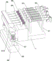
Fig. 1 is a schematic perspective view of the present invention.
Fig. 2 is a schematic perspective view of the table, main motor and leveling mechanism of the present invention.
Fig. 3 is a schematic perspective view of the carriage plate and the traveling mechanism according to the present invention.
Fig. 4 is a schematic perspective view of the flattening mechanism of the present invention.
Fig. 5 is a schematic perspective view of the workbench, the support plate and the leveling mechanism of the present invention.
Description of reference numerals: 1_ table, 2_ carriage plate, 3_ main motor, 4_ leveling mechanism, 41_ first column jacket, 42_ crank shaft, 43_ web, 44_ second column jacket, 45_ circular pressing plate, 46_ first rotating shaft, 47_ first belt device, 5_ traveling mechanism, 51_ front rotating shaft, 52_ rear rotating shaft, 53_ crawler device, 54_ slow motor, 55_ second belt device, 6_ leveling mechanism, 61_ third column jacket, 62_ first push rod, 63_ first spring, 64_ fourth column jacket, 65_ column wedge, 66_ second spring, 67_ fifth column jacket, 68_ sliding column, 69_ gravity plate, 610_ column push plate, 7_ leveling mechanism, 71_ sixth column jacket, 72_ push plate, 73_ seventh column jacket, 74_ push column, 75_ third spring, 76_ lug.
Detailed Description
The following description is only a preferred embodiment of the present invention, and does not limit the scope of the present invention.
Example 1
The utility model provides a high-efficient equipment that levels of ground for construction, as shown in figure 1, including workstation 1, mounting panel 2, main motor 3, leveling mechanism 4 and advancing mechanism 5, 1 bottom of workstation is connected with mounting panel 2, is connected with advancing mechanism 5 between the both sides around the mounting panel 2, and 1 top intermediate junction of workstation has main motor 3, is connected with leveling mechanism 4 between 1 top of workstation and the 3 output shafts of main motor.
When people need level the ground, people can place this equipment on the ground, start advancing mechanism 5 and main motor 3, advancing mechanism 5 drives this equipment and moves to the right side, and main motor 3 output shaft rotates and drives leveling mechanism 4 and carry out continuous compaction to the ground, can level the ground like this, and when not using this device, it can to close advancing mechanism 5 and main motor 3.
Example 2
On the basis of embodiment 1, as shown in fig. 2 to 3, the leveling mechanism 4 includes a first column sleeve 41, a crank shaft 42, a connecting plate 43, a second column sleeve 44, a circular pressing plate 45, a first rotating shaft 46 and a first belt device 47, the first column sleeve 41 is connected to the front and the rear of the right side of the top of the workbench 1, the crank shaft 42 is rotatably connected between the first column sleeves 41, the second column sleeve 44 is uniformly connected to the right arm of the workbench 1, the first rotating shaft 46 is slidably connected to the second column sleeve 44, the circular pressing plate 45 is connected to the bottom end of the first rotating shaft 46, the connecting plate 43 is rotatably connected between the first rotating shaft 46 on the same side of the crank shaft 42, and the first belt device 47 is connected between the left and right ends of the crank shaft 42 and the left and right sides of.
When people need level the ground, people can place this equipment on the ground, start advancing mechanism 5 and main motor 3, main motor 3 output shaft rotates and drives first belt means 47, crank axle 42 and connecting plate 43 constantly rotate, and then drive first pivot 46 and circular pressing plate 45 and constantly reciprocate, every circular pressing plate 45 is respectively in disorder to remove, evenly carry out the compaction to the ground, under advancing mechanism 5's effect, make this device constantly move right, carry out the compaction to the ground of large tracts of land, when not using this device, it can to close advancing mechanism 5 and main motor 3.
The traveling mechanism 5 comprises a front rotating shaft 51, a rear rotating shaft 52, a crawler belt device 53, a slow motor 54 and a second belt device 55, wherein the front rotating shaft 51 is rotatably connected between the front side and the rear side of the left part of the support plate 2, the rear rotating shaft 52 is rotatably connected between the front side and the rear side of the right part of the support plate 2, the slow motor 54 is connected in the middle of the top of the support plate 2, the second belt device 55 is connected between the front side and the rear side of the front rotating shaft 51 and an output shaft of the slow motor 54, and the crawler belt device 53 is connected between the front rotating shaft 51 and the rear rotating shaft.
When the device needs to move rightwards, the slow motor 54 is started, the output shaft of the slow motor 54 rotates to drive the second belt device 55, the front rotating shaft 51, the crawler belt device 53 and the rear rotating shaft 52 to rotate continuously, so that the device can move rightwards continuously, the effect of leveling the foundation can be achieved, and when the device is not used, the slow motor 54 is closed.
Example 3
On the basis of the embodiment 2, as shown in fig. 4-5, the device further comprises a flattening mechanism 6, wherein the flattening mechanism 6 comprises a third column sleeve 61, a first push rod 62, a first spring 63, a fourth column sleeve 64, a wedge-shaped block 65 with a column, a second spring 66, a fifth column sleeve 67, a sliding column 68, a gravity plate 69 and a pushing plate 610 with a column, the third column sleeve 61 is uniformly connected to the left and right sides of the top of the right side of the workbench 1, the first push rod 62 is slidably connected between the third column sleeves 61 on the same side, the right end of the first push rod 62 is in press fit with the crank shaft 42, the first spring 63 is connected between the left side of the first push rod 62 and the third column sleeve 61 on the left side, the first spring 63 is sleeved outside the first push rod 62, the left side of the top of the workbench 1 is uniformly connected with the fourth column sleeve 64, the wedge-shaped block 65 with a column is slidably connected between the fourth column sleeves 64, the right end of the wedge-shaped block 65 with, all be connected with second spring 66 between area post wedge 65 right side and the fourth post cover 64 right side, both sides all are connected with fifth post cover 67 around the 1 left wall of workstation, equal sliding connection has slip post 68 on the fifth post cover 67, be connected with gravity plate 69 between the slip post 68 bottom, be connected with the fourth spring between slip post 68 upper portion and the fifth post cover 67 top, the fourth spring all overlaps in the slip post 68 outside, gravity plate 69 top is connected with area post slurcam 610, area post slurcam 610 top and area post wedge 65 extrusion fit.
When people need to flatten the compacted foundation, the crankshaft 42 rotates and constantly extrudes the first push rod 62, under the effect of the first spring 63, make the first push rod 62 constantly move left and right, and then make the first push rod 62 constantly extrude and take post wedge 65, under the effect of the second spring 66, drive and take post wedge 65 constantly to move left and right, and then make and take post wedge 65 to extrude and take post pushing plate 610, under the effect of the third spring 75, make and take post pushing plate 610, slip post 68 and gravity plate 69 constantly reciprocate, and then make gravity plate 69 constantly press the foundation, the operation above the repetition makes the foundation more level and more smooth.
Still including pushing flat mechanism 7, push flat mechanism 7 is including sixth post cover 71, push pedal 72, seventh post cover 73, promote post 74, third spring 75 and lug 76, both sides all are connected with lug 76 around anterior pivot 51, both sides are connected with seventh post cover 73 around the mounting panel 2 right part, all sliding type connection has the promotion post 74 on the seventh post cover 73, promote post 74 left end all with lug 76 extrusion fit, it all is connected with third spring 75 to promote between post 74 right part and the seventh post cover 73 right side, third spring 75 all overlaps in the promotion post 74 outside, both sides all are connected with sixth post cover 71 around the workstation 1 right part, sliding type connection has push pedal 72 between the sixth post cover 71, push pedal 72 both sides all are connected with promotion post 74 around.
When lug 76 moves extrusion and promotes post 74 to the right side, make and promote post 74 and push pedal 72 and move right, third spring 75 is compressed, when lug 76 with promote post 74 separation, under the effect of third spring 75, make and promote post 74 and push pedal 72 and move left and reset, push pedal 72 constantly moves about and can constantly carry out the shovel to the stone on the ground and level.
The technical principle of the embodiment of the present invention is described above in conjunction with the specific embodiments. The description is only intended to explain the principles of embodiments of the invention and should not be taken in any way as limiting the scope of the embodiments of the invention. Based on the explanations herein, those skilled in the art will be able to conceive of other embodiments of the present invention without inventive step, and these embodiments will fall within the scope of the present invention.
Claims (7)
1. The utility model provides a high-efficient equipment that levels of foundation for construction, characterized by, including:
the device comprises a workbench (1) and a support plate (2), wherein the support plate (2) is connected to the bottom of the workbench (1);
the advancing mechanism (5) is connected between the two sides of the support plate (2);
the top of the workbench (1) is connected with the main motor (3);
the leveling mechanism (4) is connected between the top of the workbench (1) and the output shaft of the main motor (3).
2. The efficient foundation leveling device for building construction as claimed in claim 1, wherein the leveling mechanism (4) comprises:
the two sides of the top of one side of the workbench (1) are connected with the first column sleeve (41);
the crank shaft (42) is rotatably connected between the first column sleeves (41);
the right arm of the workbench (1) is uniformly connected with a second column sleeve (44);
the first rotating shaft (46) and the second cylinder sleeve (44) are both connected with the first rotating shaft (46) in a sliding manner;
the bottom ends of the first rotating shafts (46) are connected with circular pressing plates (45) used for pressing a foundation;
the connecting plate (43) is rotatably connected between the first rotating shaft (46) on the same side and the crankshaft (42);
and the first belt devices (47) are connected between both ends of the crank shaft (42) and both sides of the output shaft of the main motor (3).
3. The apparatus for efficiently leveling foundation for construction according to claim 2, wherein the advancing means (5) comprises:
the front rotating shaft (51) is rotatably connected between the two sides of the support plate (2);
the rear rotating shaft (52) is rotatably connected between two sides of the support plate (2) far away from the front rotating shaft (51);
the top of the bracket plate (2) is connected with the slow motor (54);
the second belt devices (55) are connected between the two sides of the front rotating shaft (51) and the output shaft of the slow motor (54);
and the crawler devices (53) are connected on two sides between the front rotating shaft (51) and the rear rotating shaft (52).
4. A high efficiency leveling apparatus for foundation construction according to claim 3, further comprising a flattening mechanism (6), wherein the flattening mechanism (6) comprises:
the third column sleeve (61) is uniformly connected to two sides of the top of the workbench (1);
the first push rods (62) are connected between the third column sleeves (61) on the same side in a sliding mode, and the first push rods (62) are in extrusion fit with the crank shaft (42);
the first spring (63) is connected between the first push rod (62) and the third column sleeve (61) on the left side, and the first springs (63) are sleeved on the outer side of the first push rod (62);
the left side of the top of the workbench (1) is uniformly connected with a fourth column sleeve (64);
the column-provided wedge block (65) is connected between the fourth column sleeve (64) in a sliding manner, and the column-provided wedge block (65) is in contact fit with the left end of the first push rod (62);
the second springs (66) are connected between the wedge-shaped blocks (65) with the columns and the fourth column sleeve (64);
the two sides of the left wall of the workbench (1) are both connected with a fifth column sleeve (67);
the sliding columns (68) are connected to the fifth column sleeves (67) in a sliding manner;
the gravity plate (69) is connected between the bottoms of the sliding columns (68), fourth springs are connected between the upper parts of the sliding columns (68) and the tops of the fifth column sleeves (67), and the fourth springs are sleeved on the outer sides of the sliding columns (68);
the top of the push plate (610) with the column is connected with the push plate (610) with the column, and the top of the push plate (610) with the column is in extrusion fit with the wedge-shaped block (65) with the column.
5. The foundation efficient leveling device for building construction as claimed in claim 4, further comprising a leveling mechanism (7), wherein the leveling mechanism (7) comprises:
the two sides of the front rotating shaft (51) are both connected with the convex blocks (76);
the seventh column sleeve (73), and the two sides of the right part of the bracket plate (2) are connected with the seventh column sleeve (73);
the pushing columns (74) are connected to the seventh column sleeve (73) in a sliding mode, and the pushing columns (74) are matched with the bumps (76) in an extruding mode;
third springs (75) are connected between the pushing columns (74) and the seventh column sleeves (73), and the third springs (75) are sleeved on the outer sides of the pushing columns (74);
the sixth column sleeve (71), and both sides of the right part of the workbench (1) are connected with the sixth column sleeve (71);
the push plate (72) is connected between the push plate (72) and the sixth column sleeve (71) in a sliding mode, and both sides of the push plate (72) are connected with the push column (74).
6. The apparatus for efficiently leveling foundation for construction according to claim 3, wherein the outer wall of the crawler means (53) is uniformly provided with the strip-shaped projections.
7. The apparatus for efficiently leveling foundation for construction according to claim 5, wherein the push plate (72) is shaped in a half arc.
Priority Applications (1)
| Application Number | Priority Date | Filing Date | Title |
|---|---|---|---|
| CN202010841711.7A CN111997117A (en) | 2020-08-20 | 2020-08-20 | High-efficient equipment that levels of ground for construction |
Applications Claiming Priority (1)
| Application Number | Priority Date | Filing Date | Title |
|---|---|---|---|
| CN202010841711.7A CN111997117A (en) | 2020-08-20 | 2020-08-20 | High-efficient equipment that levels of ground for construction |
Publications (1)
| Publication Number | Publication Date |
|---|---|
| CN111997117A true CN111997117A (en) | 2020-11-27 |
Family
ID=73473385
Family Applications (1)
| Application Number | Title | Priority Date | Filing Date |
|---|---|---|---|
| CN202010841711.7A Pending CN111997117A (en) | 2020-08-20 | 2020-08-20 | High-efficient equipment that levels of ground for construction |
Country Status (1)
| Country | Link |
|---|---|
| CN (1) | CN111997117A (en) |
Cited By (2)
| Publication number | Priority date | Publication date | Assignee | Title |
|---|---|---|---|---|
| CN112854178A (en) * | 2021-01-18 | 2021-05-28 | 浙江交工金筑交通建设有限公司 | Road surface construction compactor |
| CN113508653A (en) * | 2021-07-13 | 2021-10-19 | 陈少铃 | Soil levelling machine for flower nursery maintenance |
Citations (5)
| Publication number | Priority date | Publication date | Assignee | Title |
|---|---|---|---|---|
| JP2007231562A (en) * | 2006-02-28 | 2007-09-13 | Shimizu Corp | Compacting machine |
| CN206843909U (en) * | 2017-05-09 | 2018-01-05 | 邱阿法 | A kind of rammer of the smooth function of band |
| CN107806124A (en) * | 2017-12-05 | 2018-03-16 | 高邮市迅达重型工程机械有限公司 | A kind of bull-dozer for integrating shovel soil and being bulldozed |
| CN108149547A (en) * | 2017-12-23 | 2018-06-12 | 深圳市晟祥知识产权有限公司 | A kind of road construction trimming device with multistage rammer column |
| CN110820485A (en) * | 2019-11-25 | 2020-02-21 | 徐晓楠 | Road roller for building engineering |
-
2020
- 2020-08-20 CN CN202010841711.7A patent/CN111997117A/en active Pending
Patent Citations (5)
| Publication number | Priority date | Publication date | Assignee | Title |
|---|---|---|---|---|
| JP2007231562A (en) * | 2006-02-28 | 2007-09-13 | Shimizu Corp | Compacting machine |
| CN206843909U (en) * | 2017-05-09 | 2018-01-05 | 邱阿法 | A kind of rammer of the smooth function of band |
| CN107806124A (en) * | 2017-12-05 | 2018-03-16 | 高邮市迅达重型工程机械有限公司 | A kind of bull-dozer for integrating shovel soil and being bulldozed |
| CN108149547A (en) * | 2017-12-23 | 2018-06-12 | 深圳市晟祥知识产权有限公司 | A kind of road construction trimming device with multistage rammer column |
| CN110820485A (en) * | 2019-11-25 | 2020-02-21 | 徐晓楠 | Road roller for building engineering |
Cited By (2)
| Publication number | Priority date | Publication date | Assignee | Title |
|---|---|---|---|---|
| CN112854178A (en) * | 2021-01-18 | 2021-05-28 | 浙江交工金筑交通建设有限公司 | Road surface construction compactor |
| CN113508653A (en) * | 2021-07-13 | 2021-10-19 | 陈少铃 | Soil levelling machine for flower nursery maintenance |
Similar Documents
| Publication | Publication Date | Title |
|---|---|---|
| CN107059570B (en) | A kind of automatic laying trade brick device | |
| CN111997117A (en) | High-efficient equipment that levels of ground for construction | |
| CN207109789U (en) | A kind of soil for building rams flat machine | |
| CN110965446B (en) | Compacting machine for filling waste and method thereof | |
| CN112832533A (en) | Concrete placement is with device that vibrates | |
| CN211848767U (en) | Tamping device for highway construction | |
| CN213559276U (en) | Mining simple and easy interim ditch processingequipment in pit | |
| CN212519889U (en) | Soil compactor is used in gardens construction | |
| CN212641423U (en) | Small-size ramming machine for construction | |
| CN220550413U (en) | Land leveling device | |
| CN212426646U (en) | Municipal works are with sunken road surface repair with shakeout device | |
| CN108978412A (en) | A kind of road surface leveling unit for pavement construction | |
| CN210766722U (en) | Ramming and compacting device for soft soil foundation | |
| CN113216135A (en) | Foundation leveling device for constructional engineering and use method thereof | |
| CN209774994U (en) | Gypsum board extrusion equipment | |
| CN107761796B (en) | Soil filling equipment for building construction | |
| CN208995883U (en) | A kind of hydraulic cushion municipal administration road surface tamping unit | |
| CN218203716U (en) | Highway construction is with convenient type rammer compactor | |
| CN111794064A (en) | Cement irrigation device for road hole construction | |
| CN205712057U (en) | A kind of rammer compacter for building of simple in construction | |
| CN219032841U (en) | Asphalt pavement compacting device | |
| CN216155379U (en) | Lifting device for building construction | |
| CN219571052U (en) | Push pipe device | |
| CN217385888U (en) | Movable optical fiber fusion splicer | |
| CN218757641U (en) | A intensity detection device that is used for highway side slope protection arch skeleton structure experiment to use |
Legal Events
| Date | Code | Title | Description |
|---|---|---|---|
| PB01 | Publication | ||
| PB01 | Publication | ||
| SE01 | Entry into force of request for substantive examination | ||
| SE01 | Entry into force of request for substantive examination | ||
| RJ01 | Rejection of invention patent application after publication | ||
| RJ01 | Rejection of invention patent application after publication |
Application publication date: 20201127 |