Intelligent machining platform
Technical Field
The invention relates to the technical field of machining, in particular to an intelligent machining platform.
Background
With the development of modern economy, the industry is more and more developed, in the industrial processing process, the processing platform is widely applied, and different workpieces are processed in different types of processing platforms.
When the current machining platform is used for machining a plate, the plate is often directly placed below the punching device, then the plate is fixed through manual operation, and the fixation is manually released after the plate is machined, so that the machining platform is very inconvenient, and the machining efficiency of the machining platform on the plate is reduced; when the current machining platform is used for machining the plates, the punched plates are mostly firstly released from fixation and replaced by a new group of plates, and then the punched plates are conveyed to the lower part of the polishing device for fixation and polishing, so that the operation is very troublesome and inconvenient, the punching, polishing and plate replacement cannot be integrated, the operation steps of operators are reduced, and the machining efficiency and effect of the whole machining platform on the plates are improved; meanwhile, the effect of the current machining platform on cleaning the surface of the plate is very limited, and the cleaning effect of the machining platform on the plate cannot be further improved, so that the functionality of the whole machining platform is greatly reduced.
Disclosure of Invention
The present invention is directed to an intelligent machining platform to solve the above-mentioned problems.
In order to achieve the purpose, the invention provides the following technical scheme: an intelligent machining platform comprises a mounting platform, wherein support legs are symmetrically mounted at four corners of the bottom of the mounting platform, a square groove is formed in the middle of the top of the mounting platform, a rotary fixing component is arranged on the inner side of the square groove, machining components are symmetrically arranged at two ends of the top of the mounting platform, a collecting box is mounted at the middle of the bottom of the mounting platform, a filter screen is mounted at the inner bottom of the collecting box, an air suction pump is mounted at one end of the bottom of the mounting platform, a connecting pipe is mounted at the input end of the air suction pump, one end, away from the air suction pump, of the connecting pipe is communicated with the bottom of one end of the collecting box, connecting bins are symmetrically mounted at the tops of two ends of the collecting box, exhaust holes communicated with the connecting bins are symmetrically and uniformly formed in the tops of two ends of the collecting, mounting bracket A is installed to the both ends symmetry of mount table top both sides, and mounting bracket A's inboard installs the mount, mounting bracket A's one side and the outside fixed connection of rotatory fixed subassembly are kept away from to the mount, control panel is installed to one side of collecting box, control panel passes through the wire and is connected with aspiration pump and servo motor electricity respectively.
Preferably, the rotary fixing component comprises a rotating rod, an auxiliary gear, a fixing ring, a fixing gear, an L-shaped clamp, a winding roll, a groove, a bearing, a connecting shaft, a mounting rack B and a limiting sliding groove, the winding roll is arranged on the inner side of the square groove, the fixing gear is symmetrically arranged on two sides of the winding roll, the fixing ring is arranged on the outer side of the fixing gear, the outer ring of the fixing ring is fixedly connected with the inner side of the square groove, one side of the fixing ring, which is close to the fixing ring, is fixedly connected with the fixing ring, the mounting rack B is symmetrically arranged at the middle positions of two sides of the top of the mounting table, the bearing is arranged at the central position of the winding roll, which is far away from one side of the servo motor, the connecting shaft is arranged on the inner side of the bearing, one side of the connecting shaft, which is far, the border position department of take-up reel both sides evenly seted up flutedly, and the inboard central point of recess puts the department and is provided with the dwang, solid fixed ring's one end is kept away from to the dwang extends to the inside of take-up reel and installs L type anchor clamps, the one end that L type anchor clamps were kept away from in the dwang outside is installed and is had the auxiliary gear with fixed gear intermeshing, gu fixed ring's inboard is seted up and is had the spacing spout of mutually supporting with the dwang.
Preferably, the processing assembly comprises a mounting seat, a mounting plate, an electric lifting rod A, a sliding groove, a sliding block, a drill bit, an electric lifting rod B, a driving motor and a polishing head, the sliding groove is symmetrically formed in the middle position of the two ends of the top of the mounting plate, the sliding block is arranged inside the sliding groove, the mounting seat is mounted at the top of the sliding block, the mounting plate is mounted at the top of the mounting seat, the electric lifting rod B is mounted at one end, far away from the mounting seat, of the bottom of the mounting plate, the driving motor is mounted at the output end of the electric lifting rod B, the polishing head is mounted at the output end of the driving motor, the drill bit is mounted at the output end of the driving motor, the electric lifting rod A is symmetrically mounted at the middle position of the two ends of the top of the mounting plate, the output end of the electric lifting rod A is fixedly, The electric lifting rod B is electrically connected with the driving motor.
Preferably, the one end that the slider is close to each other is installed and is mutually supported the backing plate with L type anchor clamps, and the top of backing plate is provided with the quad slit.
Preferably, the bottom of the supporting leg is provided with a universal wheel, and the universal wheel is provided with a braking device.
Preferably, the bottom of one end of the collecting box is hinged with a bin door, and a handle is arranged on the outer side of the bin door.
Preferably, the bottom of the air pump is provided with a support plate, and the bottom of the support plate is provided with a support rod fixedly connected with the support leg.
Preferably, a rubber pad is arranged at one end, close to the rotating rod, in the L-shaped clamp.
Preferably, the auxiliary frame is installed at the bottom of the inner side of the support leg, and the other end of the auxiliary frame is fixedly installed at the bottom of the support leg on the same side.
Preferably, the inlet end of the fixing ring close to the limiting sliding groove is gradually close to the outer side of the winding roll.
Compared with the prior art, the invention provides an intelligent machining platform, which has the following beneficial effects:
1. the invention uses the matching use of the mounting rack A, the rotary fixing component, the mounting platform, the square groove, the servo motor and the fixing rack, the servo motor drives the winding disc to rotate, a group of rotating rods at the top of the outer side of the winding disc can gradually enter the limiting sliding groove, the fixing ring gradually approaches to the outer side of the winding disc from the top, so that the rotating rods are forced to gradually move towards the inner part of the winding disc, and then the two groups of corresponding L-shaped clamps are matched, so that the plates on the two groups of L-shaped clamps can be automatically clamped and fixed, when the rotating rods leave the inner part of the limiting sliding groove, the plates are not tightly clamped and fixed between the two groups of L-shaped clamps because of no limitation of the limiting sliding groove, the operation personnel can directly take the plates from the tops of the two groups of L-shaped clamps and replace a new group of plates, the operation is very convenient, and the manual fixing, the processing efficiency of the intelligent machining platform on the plate is greatly improved.
2. According to the invention, through the processing assembly, the rotary fixing assembly, the mounting table, the square groove and the base plate, and by matching with the rotating structure of the winding roll, in the rotating process of the winding roll, as the fixing ring and the fixed gear are fixedly connected with the mounting table, the auxiliary gear is forced to rotate at the outer ring part of the fixed gear and rotate by taking the rotating rod as an axis, when one group of plates are subjected to punching processing by the drill bit, the other group of punched plates are polished by the polishing head, and one group positioned at the inner top of the winding roll can also replace the plates on the two groups of L-shaped clamps.
3. According to the invention, through the cooperation of the air suction pump, the connecting pipe, the collecting box, the connecting bin, the filter screen and the exhaust hole with the autorotation structure of the L-shaped clamp, the L-shaped clamp can autorotate when the winding roll rotates, so that fragments generated in the processing process fall into the collecting box from the surface of a plate, the air suction pump forces the interior of the collecting box to be in a negative pressure state through the connecting pipe, the fragments scattered in the collecting box are sucked to the inner bottom of the collecting box and are filtered and blocked through the filter screen, and then through the cooperation of the two groups of connecting bins and the exhaust hole, the filtered air is blown into the interior of the collecting box, and the plate on the L-shaped clamp in the collecting box is blown to clean the fragments.
Drawings
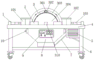
FIG. 1 is a front view of the present invention;
FIG. 2 is a front cross-sectional view of the present invention;
FIG. 3 is a top view of the mounting table of the present invention;
FIG. 4 is a partial side cross-sectional view of the present invention;
FIG. 5 is a perspective view of the winding roll of the present invention;
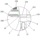
FIG. 6 is an enlarged view taken at A of FIG. 2 according to the present invention;
FIG. 7 is an enlarged view of FIG. 4 at B in accordance with the present invention;
fig. 8 is an enlarged view of fig. 4 at C according to the present invention.
In the figure: 1. processing the assembly; 101. a mounting seat; 102. mounting a plate; 103. an electric lifting rod A; 104. a chute; 105. a slider; 106. a drill bit; 107. an electric lifting rod B; 108. a drive motor; 109. polishing head; 2. a mounting frame A; 3. a rotating and fixing component; 301. rotating the rod; 302. an auxiliary gear; 303. a fixing ring; 304. fixing a gear; 305. an L-shaped clamp; 306. a take-up reel; 307. a groove; 308. a bearing; 309. a connecting shaft; 310. a mounting frame B; 311. a limiting chute; 4. an installation table; 5. an air pump; 6. a support leg; 7. a connecting pipe; 8. a collection box; 9. a control panel; 10. a connecting bin; 11. a filter screen; 12. a square groove; 13. a servo motor; 14. a fixed mount; 15. an exhaust hole; 16. a backing plate.
Detailed Description
The technical solutions in the embodiments of the present invention will be clearly and completely described below with reference to the drawings in the embodiments of the present invention, and it is obvious that the described embodiments are only a part of the embodiments of the present invention, and not all embodiments, and all other embodiments obtained by a person of ordinary skill in the art without creative efforts based on the embodiments of the present invention belong to the protection scope of the present invention.
Referring to fig. 1-8, the present invention provides a technical solution: an intelligent machining platform comprises an installation platform 4, support legs 6 are symmetrically installed at four corners of the bottom of the installation platform 4, universal wheels are installed at the bottoms of the support legs 6, braking devices are installed on the universal wheels, a square groove 12 is formed in the middle of the top of the installation platform 4, a rotary fixing assembly 3 is arranged on the inner side of the square groove 12, machining assemblies 1 are symmetrically arranged at two ends of the top of the installation platform 4, each machining assembly 1 comprises an installation seat 101, an installation plate 102, an electric lifting rod A103, a sliding groove 104, a sliding block 105, a drill bit 106, an electric lifting rod B107, a driving motor 108 and a grinding head 109, the sliding grooves 104 are symmetrically formed in the middle of the two ends of the top of the installation platform 4, the sliding block 105 is arranged inside the sliding groove 104, a base plate 16 matched with an L-shaped clamp 305 is installed at one end, close to each other, of the sliding block 105, the stability among the panel course of working helps improving, mount pad 101 is installed at the top of slider 105, mounting panel 102 is installed at the top of mount pad 101, and mounting panel 102 bottom is kept away from the one end of mount pad 101 and is installed electric lift bar B107, driving motor 108 is installed to electric lift bar B107's output, grinding head 109 is installed to a set of driving motor 108's output, drill bit 106 is installed to other end driving motor 108's output, electric lift bar A103 is installed to the intermediate position department symmetry at mount table 4 top both ends, and electric lift bar A103's output and an adjacent set of mount pad 101 fixed connection, control panel 9 passes through the wire respectively with electric lift bar A103, electric lift bar B107 and driving motor 108 electricity are connected, help simultaneously to punch a polishing to panel.
The middle position of the bottom of the mounting platform 4 is provided with a collecting box 8, the inner bottom of the collecting box 8 is provided with a filter screen 11, the bottom of one end of the collecting box 8 is hinged with a bin door, the outer side of the bin door is provided with a handle which is convenient to open the bin door to perform centralized treatment on the fragments collected in the collecting box 8, one end of the bottom of the mounting platform 4 is provided with an air pump 5, the bottom of the air pump 5 is provided with a support plate, the bottom of the support plate is provided with a support rod fixedly connected with the support legs 6, the improvement of the stability of the air pump 5 is facilitated, the bottom of the inner side of the support legs 6 is provided with an auxiliary frame, the other end of the auxiliary frame is fixedly arranged with the bottom of the support legs 6 on the same side, the improvement of the stability of the whole device supported by the support legs 6, the top symmetry at collecting box 8 both ends is installed and is connected storehouse 10, and the top symmetry at both ends evenly sets up and is connected the exhaust hole 15 of storehouse 10 intercommunication in the collecting box 8, and the output of aspiration pump 5 communicates with the inside of two sets of connection storehouses 10 respectively, and mounting bracket A2 is installed to the both ends symmetry of 4 top both sides of mount table, and the mount 14 is installed to mounting bracket A2's inboard.
The rotary fixing component 3 comprises a rotating rod 301, an auxiliary gear 302, a fixing ring 303, a fixed gear 304, an L-shaped clamp 305, a winding roll 306, a groove 307, a bearing 308, a connecting shaft 309, a mounting rack B310 and a limit sliding groove 311, wherein the winding roll 306 is arranged on the inner side of the square groove 12, the fixed gear 304 is symmetrically arranged on two sides of the winding roll 306, the fixing ring 303 is arranged on the outer side of the fixed gear 304, the inlet end of the fixing ring 303 close to the limit sliding groove 311 is gradually close to the outer side of the winding roll 306, so that the rotating rod 301 is pushed towards the inner part of the winding roll 306, the outer ring part of the fixing ring 303 is fixedly connected with the inner side of the square groove 12, one side of the fixing rack 14 close to the fixing ring 303 is fixedly connected with the fixing ring 303, the mounting rack B310 is symmetrically arranged at the middle positions, a connecting shaft 309 is arranged on the inner side of the bearing 308, one side of the connecting shaft 309, which is far away from the winding roll 306, is fixedly connected with a mounting frame B310, the central position of one side of the winding roll 306, which is far away from the servo motor 13, is in transmission connection with the output end of the servo motor 13, grooves 307 are uniformly formed in the edge positions of two sides of the winding roll 306, a rotating rod 301 is arranged at the central position of the inner side of the groove 307, one end of the rotating rod 301, which is far away from the fixing ring 303, extends into the winding roll 306 and is provided with an L-shaped clamp 305, a rubber pad is arranged at one end, which is close to the rotating rod 301, of the L-shaped clamp 305, so that the firmness of the L-shaped clamp 305 in clamping a plate is improved, an auxiliary gear 302 meshed with the fixing gear 304 is arranged at one end, which is far away from the L-shaped, one side of the fixing frame 14 far away from the mounting frame A2 is fixedly connected with the outer side of the rotary fixing component 3, one side of the collecting box 8 is provided with a control panel 9, and the control panel 9 is electrically connected with the air suction pump 5 and the servo motor 13 through leads respectively.
Example 1, as shown in fig. 1, 2, 3, 4, 5, 7 and 8, when a sheet material is processed, the servo motor 13 is controlled by the control panel 9 to drive the winding roll 306 to rotate counterclockwise, the angle of each rotation of the servo motor 13 is 45 °, the servo motor 13 is rotated once, the sheet material is placed on top of a new pair of L-shaped clamps 305, when the winding roll 306 rotates, the rotating rod 301 is gradually moved towards the winding roll 306 due to the top end of the fixing ring 303 approaching to the end of the drill 106, until the auxiliary gear 302 moves into the groove 307, and then a section of the fixing ring 303 is kept at the same level with the winding roll 306, the rotating rod 301 moves towards the inside of the winding roll 306, the two groups of L-shaped clamps 305 are forced to tightly clamp and fix the sheet material above the fixing ring 303 and the fixing ring 304, and the fixing ring is fixedly connected with the mounting table 4 through the mounting frame a2 and the fixing frame 14, the auxiliary gear 302 is forced to rotate at the outer ring part of the fixed gear 304 and rotate around the rotating rod 301, the rotation of the auxiliary gear 302 also drives the plate on the L-shaped clamp 305 to rotate, and when the L-shaped clamp 305 moves to the top, the bottom or both ends, the plate on the L-shaped clamp 305 is in a state of one surface facing upwards, so that subsequent operations such as punching, polishing or replacing the plate are facilitated.
Embodiment 2, as shown in fig. 1, 2, 3 and 6, when a set of L-shaped clamps 305 moves to an end close to the drill 106, the control panel 9 controls a corresponding set of electric lifting rods a103 to extend, and pushes the mounting base 101 and the slider 105 to approach the winding roll 306, in the process, the backing plate 16 gradually moves to a position right below the two sets of L-shaped clamps 305, and holds the two sets of L-shaped clamps 305, and then controls the electric lifting rods B107 to extend, and turns on the driving motor 108 connected to the drill 106, so as to perform drilling processing on the sheet material by the drill 106; at this time, the plate on the other set of L-shaped jigs 305 is moved to the end close to the polishing head 109, and the plate therebelow is polished by the polishing head 109 while the drill 106 is drilling.
Example 3, as shown in fig. 1, 2 and 6, when it is desired to avoid scattering of chips generated by machining around, after each set of L-shaped jigs 305 is rotated to the inside of the collection tank 8, the suction pump 5 is controlled to start operating by the control panel 9, the suction pump 5 forces the inside of the collection tank 8 to be in a negative pressure state through the connection pipe 7, so that the debris scattered inside the collection tank 8 is sucked to the inner bottom of the collection tank 8, and is filtered and blocked by a filter screen 11, and then the filtered air is blown into the collecting box 8 by the matching of two groups of connecting bins 10 and exhaust holes 15, carry out the wind to panel on the inside L type anchor clamps 305 of collecting box 8 and blow the clearance piece, because L type anchor clamps 305 can the rotation, further improve the wind and blow the effect of clearance panel surface piece, regularly open the bin gate of collecting box 8 one end bottom, carry out centralized processing to the piece of bottom collection in the collecting box 8.
The working principle is as follows: before use, the device is powered on, then a plate is manually placed on the pair of L-shaped clamps 305 at the inner top of the winding roll 306, then the servo motor 13 is controlled by the control panel 9 to drive the winding roll 306 to rotate anticlockwise, the rotating angle of the servo motor 13 is 45 degrees every time, and the plate is placed on the top of a new pair of L-shaped clamps 305 every time the servo motor 13 rotates once; when the winding roll 306 rotates, since the tip of the fixing ring 303 gradually approaches the winding roll 306 toward the end close to the drill 106, the rotating rod 301 is gradually forced to move toward the inside of the winding roll 306 until the auxiliary gear 302 moves into the inside of the groove 307, while the subsequent length of the retaining ring 303 remains at the same level as the take-up reel 306, when the rotating rod 301 moves towards the interior of the winding roll 306, the two sets of L-shaped clamps 305 are forced to tightly clamp and fix the plate above the L-shaped clamps, and because the fixed ring 303 and the fixed gear 304 are both fixedly connected with the mounting platform 4 through the mounting rack a2 and the fixing rack 14, the auxiliary gear 302 is forced to rotate at the outer ring part of the fixed gear 304 and rotate around the rotating rod 301, the rotation of the auxiliary gear 302 drives the plate on the L-shaped clamp 305 to rotate along with the plate, when the L-shaped clamp 305 moves to the top, bottom or both ends, the plates on the L-shaped clamp 305 are all in a state of facing upward; when one group of L-shaped clamps 305 moves to one end close to the drill 106, the control panel 9 controls the corresponding group of electric lifting rods A103 to extend, the mounting base 101 and the sliding block 105 are pushed to approach the winding roll 306, the backing plate 16 gradually moves to the position right below the two groups of L-shaped clamps 305 in the process, the two groups of L-shaped clamps 305 are supported, the electric lifting rods B107 are controlled to extend, the driving motor 108 connected with the drill 106 is started, and the drill 106 is used for punching the sheet; at this time, the plate on the other group of L-shaped clamps 305 moves to one end close to the polishing head 109, and the polishing head 109 polishes the plate below the plate while the drill 106 drills a hole; when L type anchor clamps 305 rotates to the inside of collection box 8, control aspiration pump 5 through control panel 9 and begin work, aspiration pump 5 forces the inside of collection box 8 to be in negative pressure state through connecting pipe 7, make the inside piece that flies apart of collection box 8 be inhaled the interior bottom of collection box 8, and filter through filter screen 11 and block, the cooperation of rethread two sets of connection storehouses 10 and exhaust hole 15, the air after will filtering blows into the inside of collection box 8, carry out the wind to the panel on the inside L type anchor clamps 305 of collection box 8 and blow the clearance piece, because L type anchor clamps 305 can the rotation, further improve the wind and blow the clastic effect in clearance panel surface, regularly open the bin gate of collection box 8 one end bottom, carry out centralized processing to the piece of bottom collection in the collection box 8.
Finally, it should be noted that the above-mentioned contents are only used for illustrating the technical solutions of the present invention, and not for limiting the protection scope of the present invention, and that the simple modifications or equivalent substitutions of the technical solutions of the present invention by those of ordinary skill in the art can be made without departing from the spirit and scope of the technical solutions of the present invention.