CN111975507A - Grain processing device for semiconductor graphite wafer and operation method thereof - Google Patents
Grain processing device for semiconductor graphite wafer and operation method thereof Download PDFInfo
- Publication number
- CN111975507A CN111975507A CN202010651323.2A CN202010651323A CN111975507A CN 111975507 A CN111975507 A CN 111975507A CN 202010651323 A CN202010651323 A CN 202010651323A CN 111975507 A CN111975507 A CN 111975507A
- Authority
- CN
- China
- Prior art keywords
- plate
- buffer
- cavity
- motor
- fixedly arranged
- Prior art date
- Legal status (The legal status is an assumption and is not a legal conclusion. Google has not performed a legal analysis and makes no representation as to the accuracy of the status listed.)
- Pending
Links
Images


Classifications
-
- B—PERFORMING OPERATIONS; TRANSPORTING
- B24—GRINDING; POLISHING
- B24B—MACHINES, DEVICES, OR PROCESSES FOR GRINDING OR POLISHING; DRESSING OR CONDITIONING OF ABRADING SURFACES; FEEDING OF GRINDING, POLISHING, OR LAPPING AGENTS
- B24B7/00—Machines or devices designed for grinding plane surfaces on work, including polishing plane glass surfaces; Accessories therefor
- B24B7/20—Machines or devices designed for grinding plane surfaces on work, including polishing plane glass surfaces; Accessories therefor characterised by a special design with respect to properties of the material of non-metallic articles to be ground
- B24B7/22—Machines or devices designed for grinding plane surfaces on work, including polishing plane glass surfaces; Accessories therefor characterised by a special design with respect to properties of the material of non-metallic articles to be ground for grinding inorganic material, e.g. stone, ceramics, porcelain
- B24B7/228—Machines or devices designed for grinding plane surfaces on work, including polishing plane glass surfaces; Accessories therefor characterised by a special design with respect to properties of the material of non-metallic articles to be ground for grinding inorganic material, e.g. stone, ceramics, porcelain for grinding thin, brittle parts, e.g. semiconductors, wafers
-
- B—PERFORMING OPERATIONS; TRANSPORTING
- B24—GRINDING; POLISHING
- B24B—MACHINES, DEVICES, OR PROCESSES FOR GRINDING OR POLISHING; DRESSING OR CONDITIONING OF ABRADING SURFACES; FEEDING OF GRINDING, POLISHING, OR LAPPING AGENTS
- B24B27/00—Other grinding machines or devices
- B24B27/0046—Column grinding machines
-
- B—PERFORMING OPERATIONS; TRANSPORTING
- B24—GRINDING; POLISHING
- B24B—MACHINES, DEVICES, OR PROCESSES FOR GRINDING OR POLISHING; DRESSING OR CONDITIONING OF ABRADING SURFACES; FEEDING OF GRINDING, POLISHING, OR LAPPING AGENTS
- B24B41/00—Component parts such as frames, beds, carriages, headstocks
- B24B41/007—Weight compensation; Temperature compensation; Vibration damping
-
- B—PERFORMING OPERATIONS; TRANSPORTING
- B24—GRINDING; POLISHING
- B24B—MACHINES, DEVICES, OR PROCESSES FOR GRINDING OR POLISHING; DRESSING OR CONDITIONING OF ABRADING SURFACES; FEEDING OF GRINDING, POLISHING, OR LAPPING AGENTS
- B24B41/00—Component parts such as frames, beds, carriages, headstocks
- B24B41/02—Frames; Beds; Carriages
-
- B—PERFORMING OPERATIONS; TRANSPORTING
- B24—GRINDING; POLISHING
- B24B—MACHINES, DEVICES, OR PROCESSES FOR GRINDING OR POLISHING; DRESSING OR CONDITIONING OF ABRADING SURFACES; FEEDING OF GRINDING, POLISHING, OR LAPPING AGENTS
- B24B41/00—Component parts such as frames, beds, carriages, headstocks
- B24B41/06—Work supports, e.g. adjustable steadies
- B24B41/068—Table-like supports for panels, sheets or the like
-
- B—PERFORMING OPERATIONS; TRANSPORTING
- B24—GRINDING; POLISHING
- B24B—MACHINES, DEVICES, OR PROCESSES FOR GRINDING OR POLISHING; DRESSING OR CONDITIONING OF ABRADING SURFACES; FEEDING OF GRINDING, POLISHING, OR LAPPING AGENTS
- B24B47/00—Drives or gearings; Equipment therefor
- B24B47/02—Drives or gearings; Equipment therefor for performing a reciprocating movement of carriages or work- tables
- B24B47/04—Drives or gearings; Equipment therefor for performing a reciprocating movement of carriages or work- tables by mechanical gearing only
-
- B—PERFORMING OPERATIONS; TRANSPORTING
- B24—GRINDING; POLISHING
- B24B—MACHINES, DEVICES, OR PROCESSES FOR GRINDING OR POLISHING; DRESSING OR CONDITIONING OF ABRADING SURFACES; FEEDING OF GRINDING, POLISHING, OR LAPPING AGENTS
- B24B47/00—Drives or gearings; Equipment therefor
- B24B47/10—Drives or gearings; Equipment therefor for rotating or reciprocating working-spindles carrying grinding wheels or workpieces
- B24B47/12—Drives or gearings; Equipment therefor for rotating or reciprocating working-spindles carrying grinding wheels or workpieces by mechanical gearing or electric power
-
- H—ELECTRICITY
- H01—ELECTRIC ELEMENTS
- H01L—SEMICONDUCTOR DEVICES NOT COVERED BY CLASS H10
- H01L21/00—Processes or apparatus adapted for the manufacture or treatment of semiconductor or solid state devices or of parts thereof
- H01L21/67—Apparatus specially adapted for handling semiconductor or electric solid state devices during manufacture or treatment thereof; Apparatus specially adapted for handling wafers during manufacture or treatment of semiconductor or electric solid state devices or components ; Apparatus not specifically provided for elsewhere
- H01L21/67005—Apparatus not specifically provided for elsewhere
- H01L21/67011—Apparatus for manufacture or treatment
- H01L21/67092—Apparatus for mechanical treatment
Abstract
The invention discloses a crystal grain processing device for a semiconductor graphite wafer, which comprises a base, wherein upright columns are arranged in the middle parts of two sides of the top surface of the base; the top surface of the base is provided with an equipment box, and the top surface of the equipment box is provided with a bearing platform; a rubber supporting plate is arranged at the top end of the fixed block, and T-shaped guide rails are arranged on the top surfaces of the bearing tables at the two sides of the fixed block; the top surface of each sliding plate is provided with an arc-shaped clamping plate; a wafer plate is arranged on the top surface of the rubber supporting plate; a driving box is arranged at the bottom of the sleeve, a rotating shaft is arranged on the inner bottom surface of the driving box, and a polishing wheel is sleeved at the bottom end of the rotating shaft; the clamping device is convenient to operate, and solves the problems that the wafer plate is easy to damage during clamping and the clamping efficiency is low because the wafer plates with different sizes are inconvenient to clamp through the driving assembly and the adjusting assembly; through removal subassembly and lifting unit, solved current crystalline grain grinding device inconvenient problem of operation when polishing the crystalline grain on the wafer board.
Description
Technical Field
The invention relates to the technical field of semiconductor graphite wafer processing, in particular to a grain processing device for a semiconductor graphite wafer and an operation method thereof.
Background
The wafer fine machining equipment is used for polishing wafers and crystal grains and improving the smoothness of the surfaces of the wafers, and in the traditional wafer fine machining process, wafer plates with different sizes are not convenient to clamp due to the complex wafer fixing mode, and meanwhile, the wafer plates are easy to damage during clamping; when the crystal grains on the wafer plate are polished, a manual polishing operation method is adopted more, so that the physical strength and energy of workers are greatly reduced due to long-time polishing operation when the crystal grains are polished, the quality of polishing the crystal grains on the wafer plate is affected, and the polishing operation of the workers is inconvenient.
Disclosure of Invention
The invention aims to solve the defects in the prior art and provides a crystal grain processing device for a semiconductor graphite wafer.
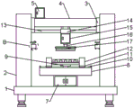
In order to achieve the purpose, the invention adopts the following technical scheme: the crystal grain processing device for the semiconductor graphite wafer comprises a base, wherein the base is in a horizontally arranged rectangular plate shape, stand columns are vertically and fixedly arranged in the middle parts of two sides of the top surface of the base, movable plates are vertically and movably arranged on the upper parts of the inner side surfaces of the two stand columns, a cross beam is transversely and fixedly arranged on the upper part between the two movable plates, a motor box is fixedly arranged in the middle part of one end of the top surface of the cross beam, and a first motor is vertically and fixedly arranged in the motor box; a rectangular equipment box is fixedly arranged in the middle of the top surface of the base, a rectangular bearing table is horizontally and fixedly arranged on the top surface of the equipment box, a rectangular fixed block is fixedly arranged in the middle of the top surface of the bearing table, a round rubber supporting plate is horizontally and fixedly arranged at the top end of the fixed block, T-shaped guide rails are transversely and fixedly arranged on the top surfaces of the bearing tables at two sides of the fixed block, sliding plates are horizontally and movably arranged on each T-shaped guide rail, and a T-shaped sliding groove is transversely formed in the bottom surface of each sliding plate in a manner of being matched with the T-shaped guide rail; the top surface of each sliding plate is vertically and fixedly provided with an arc-shaped clamping plate, and the inner arc surfaces of the two arc-shaped clamping plates are oppositely arranged; a wafer plate is horizontally placed on the top surface of the rubber supporting plate;
two transversely fixed guide bar that is equipped with between the bottom of movable plate the movable sleeve is equipped with the sleeve pipe on the guide bar the fixed drive case that is equipped with in sheathed tube bottom the vertical second motor that is provided with in the drive case the fixed first bearing that is equipped with in interior bottom surface middle part of drive case vertical fixed axis of rotation that is equipped with in the inner circle of first bearing, the coaxial rigid coupling of motor shaft of shaft coupling and second motor is passed through on the top of axis of rotation, just the bottom of driving case is run through out to the bottom of axis of rotation the fixed cover of bottom level of axis of rotation is equipped with the emery wheel.
Preferably, a circular lifting cavity is vertically formed in each upright column along the height direction, and a lifting assembly is arranged in each lifting cavity; a rectangular moving cavity is transversely formed in the middle of the inside of the cross beam, and a moving assembly is arranged in the moving cavity; a rectangular transmission cavity is formed in the cross beam on one side of the moving cavity; a driving assembly is arranged in the equipment box; the middle part in the bearing plate is transversely provided with a rectangular adjusting cavity, and an adjusting component is arranged in the adjusting cavity.
Preferably, the lifting assembly comprises an electric pushing cylinder, a cylindrical block and a connecting plate, the bottom of each lifting cavity is vertically and fixedly provided with the electric pushing cylinder, the top of each lifting cavity is vertically and movably provided with the cylindrical block, and the top of the telescopic end of each electric pushing cylinder is fixedly connected with the bottom surface of the cylindrical block; the middle part of one side of each cylindrical block is transversely and fixedly connected with a connecting plate, the upper part of the inner side surface of each upright post is vertically provided with a strip-shaped opening, and one end of each connecting plate extends out of the strip-shaped opening and is fixedly connected with the outer side surface of the movable plate.
Preferably, the moving assembly comprises a screw rod, a threaded cylinder, a connecting rod, a driving bevel gear and a driven bevel gear, second bearings are fixedly arranged on the inner walls of the two sides of the moving cavity, the screw rod is transversely arranged in the moving cavity, and the two ends of the screw rod are fixedly connected in the inner ring of the first bearing; a threaded cylinder is movably sleeved on a rod body of the lead screw, connecting rods are vertically and fixedly connected to two sides of the bottom of the threaded cylinder, strip-shaped openings are transversely formed in the inner bottom surface of the moving cavity, and the bottom end of each connecting rod extends out of the strip-shaped opening to be fixedly connected with a top pipe body of the sleeve; one end of the lead screw penetrates into the transmission cavity, a driven bevel gear is sleeved at the end of the lead screw, the bottom end of the motor shaft of the first motor penetrates into the transmission cavity, a driving bevel gear is fixedly sleeved at the bottom end of the motor shaft of the first motor, and the driving bevel gear is in meshing transmission with the driven bevel gear.
Preferably, the adjusting assembly comprises a rotating rod, a baffle ring, a threaded sleeve and a connecting column, third bearings are fixedly arranged on the inner walls of the two sides of the adjusting cavity, the rotating rod is transversely arranged in the adjusting cavity, and the two ends of the rotating rod are fixedly connected in the inner ring of the third bearings; baffle rings are fixedly sleeved on two sides of the middle part of the rotating rod body, and a forward thread and a reverse thread are respectively arranged on the rotating rod body outside each baffle ring; threaded sleeves are movably sleeved on two sides of the rod body of the rotating rod, a connecting column is vertically and fixedly arranged at the top of each threaded sleeve, a strip-shaped rectangular opening is formed in the inner top surface of the adjusting cavity along the length direction, and the rectangular opening is located at the front end of the T-shaped guide rail; the top end of each connecting column extends out of the rectangular opening and is fixedly connected with the bottom surface of the sliding plate.
Preferably, the driving assembly comprises a third motor, a transmission shaft, a driving bevel gear and a driven bevel gear, the third motor is vertically and fixedly arranged in the middle of the inside of the equipment box, and storage batteries are arranged on two sides of the inside of the equipment box; the fixed fourth bearing that is equipped with in the middle part of the interior top surface of equipment box vertical fixed transmission shaft that is equipped with in the inner circle of fourth bearing, the bottom of transmission shaft passes through the coaxial rigid coupling of motor shaft of shaft coupling and third motor, just the top of transmission shaft runs through into adjusts the intracavity the fixed cover in top of transmission shaft is equipped with drive bevel gear, two fixed cover is equipped with driven bevel gear on the body of rod of the dwang between the fender ring, just drive bevel gear and driven bevel gear meshing transmission.
Preferably, each arc-shaped clamping plate is vertically and movably provided with an arc-shaped rubber pad on the inner arc surface, each arc-shaped rubber pad is transversely and fixedly provided with a clamping force spring at equal distance from the top to the bottom of the outer arc surface, and the outer end of each clamping force spring is fixedly connected with the inner arc surface of each arc-shaped clamping plate.
Preferably, a rectangular buffer box is fixedly arranged in the middle of the inner side face of each upright post, a rectangular buffer cavity is formed in each buffer box, and a buffer assembly is arranged in each buffer cavity; the buffer assembly comprises buffer plates, buffer springs, stabilizer bars, buffer rods and buffer base plates, the buffer plates are horizontally and movably arranged in each buffer cavity, the buffer springs are vertically and fixedly arranged in the middle of the bottom surface of each buffer plate, and the bottom ends of the buffer springs are fixedly connected with the inner bottom surface of the buffer cavity; stabilizing bars are vertically and fixedly arranged at four corners of the bottom surface of each buffer plate, and the bottom end of each stabilizing bar movably penetrates out of the buffer cavity; every the vertical fixed buffer beam that is equipped with of top surface middle part office of buffer board, and every the top of buffer beam all runs through out the top of buffering box, every the equal horizontally fixed cushion plate that is equipped with in top of buffer beam.
The invention also provides an operation method of the grain processing device for the semiconductor graphite wafer, which comprises the following steps:
firstly, electrically connecting a first motor, an electric pushing cylinder, a second motor and a third motor with a storage battery through leads respectively, placing a wafer plate on the top surface of a rubber supporting plate, and then adjusting the distance between arc-shaped clamping plates at two sides according to the size of the wafer plate;
driving the adjusting assembly through the control driving assembly, driving the sliding plate to slide towards the T-shaped guide rail through the adjusting assembly, driving the arc-shaped clamping plate to move inwards through inward sliding of the sliding plate, and clamping the arc-shaped rubber pads on two sides of the wafer plate through inward movement of the arc-shaped clamping plate;
thirdly, adjusting the position of a polishing wheel according to the position of the wafer plate, controlling a first motor to drive a moving assembly, driving a sleeve to transversely move on a guide rod through the moving assembly, and driving a rotating shaft at the bottom end of a driving box and the polishing wheel to transversely move and adjust through the transverse movement of the sleeve;
fourthly, driving the polishing wheel at the bottom end of the rotating shaft to rotate by controlling a second motor, driving the moving plate to lift on the inner side surface of the upright post by controlling the lifting assembly, driving the cross beam and the polishing wheel at the bottom to descend by lifting the moving plate, and polishing the crystal grains on the surface of the wafer plate by descending the polishing wheel;
and step five, resetting the device and turning off the power supply after the polishing work is finished.
Compared with the prior art, the invention has the beneficial effects that:
1. the adjusting assembly is driven by the driving assembly, the arc-shaped clamping plates on the sliding plate are driven by the adjusting assembly to move inwards, the arc-shaped rubber pads can be used for clamping and fixing the wafer plates with different sizes conveniently due to the inwards movement of the arc-shaped clamping plates, the abrasion and extrusion generated when the wafer plates are clamped and fixed can be effectively reduced through the arc-shaped rubber pads and the clamping force springs, the clamping use range of the device is effectively enlarged through the movable arc-shaped clamping plates, the wafer plates with different sizes can be clamped and fixed quickly, the clamping efficiency of the wafer plates is effectively improved, the problem that the wafer plates are easily damaged when the existing wafer plate clamping mechanism clamps the wafer plates is solved, and the problems that the existing clamping mechanism is not convenient to clamp the wafer plates with different sizes quickly and the clamping efficiency is low are solved;
2. the first motor drives the moving assembly, the moving assembly is convenient for driving the polishing wheel below the driving cavity to move transversely and adjust, the movable adjustment of the polishing wheel is convenient for moving and adjusting according to the fixed position of the wafer plate and the position of the crystal grain to be polished, the lifting assembly drives the polishing wheel to lift so as to polish the crystal grain on the wafer plate, the labor intensity of workers during polishing is effectively reduced, and the polishing efficiency of the crystal grain is effectively improved; the problem that the conventional crystal grain polishing device is inconvenient to operate when polishing crystal grains on a wafer plate is solved; the cross beam is effectively reduced through the buffer assembly, the grinding wheel is driven by the cross beam to generate impact force to the wafer plate when the grinding wheel descends, and the protection performance to the wafer plate is effectively improved conveniently.
Drawings
The accompanying drawings, which are included to provide a further understanding of the invention and are incorporated in and constitute a part of this application, illustrate embodiment(s) of the invention and together with the description serve to explain the invention without limiting the invention. In the drawings:
FIG. 1 is a schematic front view of the present invention;
FIG. 2 is a front view in cross section of the present invention;
FIG. 3 is an enlarged view of the portion A of FIG. 2 according to the present invention;
FIG. 4 is an enlarged schematic view of the cross-sectional structure of the portion B in FIG. 1 according to the present invention;
FIG. 5 is a schematic diagram of the method of operation of the present invention;
number in the figure: the device comprises a base 1, an upright column 2, a moving plate 3, a cross beam 4, a motor box 5, a first motor 6, an equipment box 7, a bearing table 8, a rubber supporting plate 9, a T-shaped guide rail 10, a sliding plate 11, an arc-shaped clamping plate 12, a guide rod 13, a sleeve 14, a driving box 15, a rotating shaft 16, a grinding wheel 17, an electric pushing cylinder 18, a cylindrical block 19, a connecting plate 20, a screw rod 21, a threaded cylinder 22, a connecting rod 23, a driving bevel gear 24, a driven bevel gear 25, a second motor 26, a rotating rod 27, a baffle ring 28, a threaded sleeve 29, a connecting rod 30, a third motor 31, a transmission shaft 32, a driving bevel gear 33, a driven bevel gear 34, an arc-shaped rubber pad 35, a clamping spring 36, a buffer box 37, a buffer plate 38, a buffer spring 39, a stabilizing.
Detailed Description
The technical solutions in the embodiments of the present invention will be clearly and completely described below with reference to the drawings in the embodiments of the present invention, and it is obvious that the described embodiments are only a part of the embodiments of the present invention, and not all of the embodiments.
Example 1: referring to fig. 1-4, the crystal grain processing device for the semiconductor graphite wafer comprises a base 1, wherein upright columns 2 are vertically and fixedly arranged in the middle of two sides of the top surface of the base 1, moving plates 3 are vertically and movably arranged on the upper portions of the inner side surfaces of the two upright columns 2, a cross beam 4 is transversely and fixedly arranged on the upper portion between the two moving plates 3, a motor box 5 is fixedly arranged in the middle of one end of the top surface of the cross beam 4, a first motor 6 is vertically and fixedly arranged in the motor box 5, and the model of the first motor 6 is T63B 4; a rectangular equipment box 7 is fixedly arranged in the middle of the top surface of the base 1, a rectangular bearing table 8 is horizontally and fixedly arranged on the top surface of the equipment box 7, a rectangular fixed block is fixedly arranged in the middle of the top surface of the bearing table 8, a circular rubber supporting plate 9 is horizontally and fixedly arranged at the top end of the fixed block, T-shaped guide rails 10 are transversely and fixedly arranged on the top surfaces of the bearing tables 8 at two sides of the fixed block, a sliding plate 11 is horizontally and movably arranged on each T-shaped guide rail 10, and a T-shaped sliding groove is transversely formed in the bottom surface of each sliding plate 11 in a manner of being matched with the T-shaped guide rail 10; the top surface of each sliding plate 11 is vertically and fixedly provided with an arc-shaped clamping plate 12, and the inner arc surfaces of the two arc-shaped clamping plates 12 are arranged oppositely; a wafer plate is horizontally placed on the top surface of the rubber supporting plate 9; a guide rod 13 is transversely and fixedly arranged between the bottoms of the two moving plates 3, a sleeve 14 is movably sleeved on the guide rod 13, a driving box 15 is fixedly arranged at the bottom of the sleeve 14, a second motor 26 is vertically arranged in the driving box 15, and the model of the second motor 26 is WKBL 2232S-1213; the fixed first bearing that is equipped with in interior bottom surface middle part of drive case 15 vertical fixed axis of rotation 16 that is equipped with in the inner circle of first bearing, the top of axis of rotation 16 passes through the coaxial rigid coupling of shaft coupling and second motor 26's motor shaft, just the bottom of axis of rotation 16 runs through the bottom of drive case 15 the fixed cover of bottom level of axis of rotation 16 is equipped with polishing wheel 17.
In the invention, a round lifting cavity is vertically arranged in each upright post 2 along the height direction, and a lifting assembly is arranged in each lifting cavity; a rectangular moving cavity is transversely formed in the middle of the inside of the cross beam 4, and a moving assembly is arranged in the moving cavity; a rectangular transmission cavity is formed in the cross beam 4 on one side of the moving cavity; a driving component is arranged in the equipment box 7; a rectangular adjusting cavity is transversely formed in the middle of the inside of the bearing plate 8, and an adjusting assembly is arranged in the adjusting cavity.
In the invention, the lifting assembly comprises an electric pushing cylinder 18, a cylindrical block 19 and a connecting plate 20, wherein the model of the electric pushing cylinder 18 is HH 110-S300-T-R10-M1-C1-P2; an electric pushing cylinder 18 is vertically and fixedly arranged at the bottom of each lifting cavity, a cylindrical block 19 is vertically and movably arranged at the top of each lifting cavity, and the top of the telescopic end of each electric pushing cylinder 18 is fixedly connected with the bottom surface of the cylindrical block 19; a connecting plate 20 is transversely and fixedly connected to the middle of one side of each cylindrical block 19, a strip-shaped opening is vertically formed in the upper portion of the inner side face of each upright post 2, and one end of each connecting plate 20 extends out of the strip-shaped opening and is fixedly connected with the outer side face of the moving plate 3.
In the invention, the moving assembly comprises a screw rod 21, a threaded cylinder 22, a connecting rod 23, a driving bevel gear 24 and a driven bevel gear 25, second bearings are fixedly arranged on the inner walls of two sides of the moving cavity, the screw rod 21 is transversely arranged in the moving cavity, and two ends of the screw rod 21 are fixedly connected in the inner ring of the first bearing; a threaded cylinder 22 is movably sleeved on a rod body of the lead screw 21, connecting rods 23 are vertically and fixedly connected to two sides of the bottom of the threaded cylinder 22, strip-shaped openings are transversely formed in the inner bottom surface of the moving cavity, and the bottom end of each connecting rod 23 extends out of the strip-shaped opening to be fixedly connected with a top pipe body of the sleeve 14; one end of the lead screw 21 penetrates into the transmission cavity, a driven bevel gear 25 is fixedly sleeved at the end of the lead screw 21, the bottom end of the motor shaft of the first motor 6 penetrates into the transmission cavity, a driving bevel gear 24 is fixedly sleeved at the bottom end of the motor shaft of the first motor 6, and the driving bevel gear 24 is in meshing transmission with the driven bevel gear 25; the movable assembly is driven by the first motor, the polishing wheel below the driving cavity is driven by the movable assembly to move transversely, the movable adjustment of the polishing wheel is convenient to move and adjust according to the position where the wafer plate is fixed and the position where the crystal grains to be polished are to be polished, the lifting assembly drives the polishing wheel to lift, the crystal grains on the wafer plate are polished conveniently, and the labor intensity of workers during polishing is effectively reduced.
In the invention, the adjusting component comprises a rotating rod 27, a baffle ring 28, a threaded sleeve 29 and a connecting column 30, third bearings are fixedly arranged on the inner walls of the two sides of the adjusting cavity, the rotating rod 27 is transversely arranged in the adjusting cavity, and the two ends of the rotating rod 27 are fixedly connected in the inner ring of the third bearing; baffle rings 28 are fixedly sleeved on two sides of the middle part of the rotating rod 27, and a forward thread and a reverse thread are respectively arranged on the rod body of the rotating rod 28 outside each baffle ring 28; threaded sleeves 29 are movably sleeved on two sides of the rod body of the rotating rod 27, a connecting column 30 is vertically and fixedly arranged at the top of each threaded sleeve 29, a strip-shaped rectangular opening is formed in the inner top surface of the adjusting cavity along the length direction, and the rectangular opening is located at the front end of the T-shaped guide rail 10; the top end of each connecting column 30 extends out of the rectangular opening to be fixedly connected with the bottom surface of the sliding plate 11; the driving assembly comprises a third motor 31, a transmission shaft 32, a driving bevel gear 33 and a driven bevel gear 34, the model of the third motor 31 is CH28-750-15S, the third motor 31 is vertically and fixedly arranged in the middle of the inside of the equipment box 7, and storage batteries are arranged on two sides of the inside of the equipment box 7; a fourth bearing is fixedly arranged in the middle of the inner top surface of the equipment box 7, a transmission shaft 32 is vertically and fixedly arranged in an inner ring of the fourth bearing, the bottom end of the transmission shaft 32 is coaxially and fixedly connected with a motor shaft of a third motor 31 through a coupler, the top end of the transmission shaft 32 penetrates through an adjusting cavity, a driving bevel gear 33 is fixedly sleeved at the top end of the transmission shaft 32, a driven bevel gear 34 is fixedly sleeved on a rod body of a rotating rod 27 between the two retaining rings 28, and the driving bevel gear 33 is in meshing transmission with the driven bevel gear 34; inwards moving through the arc-shaped clamping plate is convenient for to enable the arc-shaped rubber pad to clamp and fix the wafer plates with different sizes, through the arc-shaped rubber pad and the clamping force spring, the abrasion generated when the wafer plates are clamped and fixed and the extrusion condition are effectively reduced, the clamping use range of the device is effectively increased through the movable arc-shaped clamping plate, the wafer plates with different sizes are convenient to rapidly fix and clamp, and the clamping efficiency of the wafer plates is effectively improved.
In the invention, an arc-shaped rubber pad 35 is vertically and movably arranged on the inner arc surface of each arc-shaped clamping plate 12, clamping force springs 36 are transversely and fixedly arranged on the top and the bottom of the outer arc surface of each arc-shaped rubber pad 35 at equal intervals, and the outer end of each clamping force spring 36 is fixedly connected with the inner arc surface of each arc-shaped clamping plate 12; a rectangular buffer box 37 is fixedly arranged in the middle of the inner side surface of each upright post 2, a rectangular buffer cavity is formed in each buffer box 37, and a buffer assembly is arranged in each buffer cavity; the buffer assembly comprises buffer plates 38, buffer springs 39, stabilizer bars 40, buffer rods 41 and buffer cushion plates 42, the buffer plates 38 are horizontally and movably arranged in each buffer cavity, the buffer springs 39 are vertically and fixedly arranged in the middle of the bottom surface of each buffer plate 38, and the bottom ends of the buffer springs 39 are fixedly connected with the inner bottom surface of the buffer cavity; stabilizing bars 40 are vertically and fixedly arranged at four corners of the bottom surface of each buffer plate 38, and the bottom end of each stabilizing bar 40 movably penetrates out of the buffer cavity; a buffer rod 41 is vertically and fixedly arranged in the middle of the top surface of each buffer plate 38, the top end of each buffer rod 41 penetrates through the top of the buffer box 37, and a buffer base plate 42 is horizontally and fixedly arranged at the top end of each buffer rod 41; the cross beam is effectively reduced through the buffer assembly, the grinding wheel is driven by the cross beam to generate impact force to the wafer plate when the grinding wheel descends, and the protection performance to the wafer plate is effectively improved conveniently.
Example 2: referring to fig. 5, in the present embodiment, the present invention further provides an operating method of a grain processing apparatus for a semiconductor graphite wafer, including the following steps:
firstly, electrically connecting a first motor 6, an electric pushing cylinder 18, a second motor 26 and a third motor 31 with a storage battery through leads respectively, placing a wafer plate on the top surface of a rubber supporting plate 9, and then adjusting the distance between arc-shaped clamping plates at two sides according to the size of the wafer plate;
step two, driving a driving bevel gear 33 at the top end of a transmission shaft 32 to rotate by controlling a third motor 31, driving a rotating rod 27 to rotate by the meshing transmission of the driving bevel gear 33 and a driven bevel gear 34, driving two threaded sleeves 29 to simultaneously move inwards by forward threads and reverse threads on a rod body of the rotating rod 27, driving a sliding plate 11 at the top end of a connecting column 30 to slide upwards in a T-shaped guide rail 10 by the inward transverse movement of the threaded sleeves 29, driving an arc-shaped clamping plate 12 to move inwards by the inward sliding of the sliding plate 11, and clamping arc-shaped rubber pads 35 at two sides of a wafer plate by the inward movement of the arc-shaped clamping plate 12;
step three, adjusting the position of a polishing wheel 17 according to the position of a wafer plate, driving a driving bevel gear 24 to rotate by controlling a first motor 6, driving a lead screw 21 to rotate by the meshing transmission of the driving bevel gear 24 and a driven bevel gear 25, driving a thread cylinder 22 to transversely move on a rod body by the rotation of the lead screw 21, driving a sleeve 14 at the bottom end of a connecting rod to transversely move on a guide rod 13 by the transverse movement of the thread cylinder 22, and driving a rotating shaft 16 at the bottom end of a driving box 15 and the polishing wheel 17 to transversely move and adjust by the transverse movement of the sleeve 14;
fourthly, the second motor 26 is controlled to drive the polishing wheel 17 at the bottom end of the rotating shaft 16 to rotate, then the cylindrical block 19 at the top end is driven to descend in the lifting cavity by controlling the extension and retraction of the electric pushing cylinder 18, the movable plate 3 at the outer end of the connecting plate 20 is driven to ascend and descend on the inner side surface of the upright post 2 by descending of the cylindrical block 19, the crossbeam 4 and the polishing wheel 17 at the bottom are driven to descend by ascending and descending of the movable plate 3, and the polishing wheel 17 is convenient for polishing crystal grains on the surface of the wafer plate;
and step five, resetting the device and turning off the power supply after the polishing work is finished.
The above description is only for the preferred embodiment of the present invention, but the scope of the present invention is not limited thereto, and any person skilled in the art should be considered to be within the technical scope of the present invention, and the technical solutions and the inventive concepts thereof according to the present invention should be equivalent or changed within the scope of the present invention.
Claims (8)
1. A grain processingequipment for semiconductor graphite wafer, including base (1), its characterized in that: the base (1) is in a horizontally arranged rectangular plate shape, stand columns (2) are vertically and fixedly arranged in the middle of two sides of the top surface of the base (1), moving plates (3) are vertically and movably arranged on the upper portions of the inner side surfaces of the two stand columns (2), a cross beam (4) is transversely and fixedly arranged on the upper portion between the two moving plates (3), a motor box (5) is fixedly arranged in the middle of one end of the top surface of the cross beam (4), and a first motor (6) is vertically and fixedly arranged in the motor box (5); a rectangular equipment box (7) is fixedly arranged in the middle of the top surface of the base (1), a rectangular bearing table (8) is horizontally and fixedly arranged on the top surface of the equipment box (7), a rectangular fixed block is fixedly arranged in the middle of the top surface of the bearing table (8), a round rubber supporting plate (9) is horizontally and fixedly arranged at the top end of the fixed block, T-shaped guide rails (10) are transversely and fixedly arranged on the top surfaces of the bearing tables (8) on the two sides of the fixed block, a sliding plate (11) is horizontally and movably arranged on each T-shaped guide rail (10), and a T-shaped sliding groove is transversely formed in the bottom surface of each sliding plate (11) in a manner of being matched with the T-shaped guide rail (10); arc-shaped clamping plates (12) are vertically and fixedly arranged on the top surface of each sliding plate (11), and the inner arc surfaces of the two arc-shaped clamping plates (12) are oppositely arranged; a wafer plate is horizontally placed on the top surface of the rubber supporting plate (9);
a guide rod (13) is transversely and fixedly arranged between the bottoms of the two moving plates (3), a sleeve (14) is movably sleeved on the guide rod (13), a driving box (15) is fixedly arranged at the bottom of the sleeve (14), a second motor (26) is vertically arranged in the driving box (15), a first bearing is fixedly arranged in the middle of the inner bottom surface of the driving box (15), a rotating shaft (16) is vertically and fixedly arranged in the inner ring of the first bearing, the top end of the rotating shaft (16) is coaxially and fixedly connected with a motor shaft of the second motor (26) through a coupler, the bottom end of the rotating shaft (16) penetrates through the bottom of the driving box (15), and a polishing wheel (17) is horizontally and fixedly sleeved at the bottom end of the rotating shaft (16);
a round lifting cavity is vertically formed in each upright post (2) along the height direction, and a lifting assembly is arranged in each lifting cavity; a rectangular moving cavity is transversely formed in the middle of the inside of the cross beam (4), and a moving assembly is arranged in the moving cavity; a rectangular transmission cavity is formed in the cross beam (4) on one side of the moving cavity; a driving component is arranged in the equipment box (7); the middle part in the bearing plate (8) is transversely provided with a rectangular adjusting cavity, and an adjusting component is arranged in the adjusting cavity.
2. The die processing apparatus for semiconductor graphite wafers as set forth in claim 1, wherein: the lifting assembly comprises electric pushing cylinders (18), cylindrical blocks (19) and a connecting plate (20), the bottom of each lifting cavity is vertically and fixedly provided with the electric pushing cylinder (18), the top of each lifting cavity is vertically and movably provided with the cylindrical block (19), and the top of the telescopic end of each electric pushing cylinder (18) is fixedly connected with the bottom surface of the cylindrical block (19); the middle part of one side of each cylindrical block (19) is transversely and fixedly connected with a connecting plate (20), the upper part of the inner side surface of each upright post (2) is vertically provided with a strip-shaped opening, and one end of each connecting plate (20) extends out of the strip-shaped opening and is fixedly connected with the outer side surface of the moving plate (3).
3. The die processing apparatus for semiconductor graphite wafers as set forth in claim 1, wherein: the moving assembly comprises a lead screw (21), a threaded cylinder (22), a connecting rod (23), a driving bevel gear (24) and a driven bevel gear (25), second bearings are fixedly arranged on the inner walls of the two sides of the moving cavity, the lead screw (21) is transversely arranged in the moving cavity, and the two ends of the lead screw (21) are fixedly connected in the inner ring of the first bearing; a threaded cylinder (22) is movably sleeved on a rod body of the lead screw (21), connecting rods (23) are vertically and fixedly connected to two sides of the bottom of the threaded cylinder (22), strip-shaped openings are transversely formed in the inner bottom surface of the moving cavity, and the bottom end of each connecting rod (23) extends out of the strip-shaped opening to be fixedly connected with a top pipe body of the sleeve (14); one end of the lead screw (21) penetrates into the transmission cavity, a driven bevel gear (25) is fixedly sleeved at the end of the lead screw (21), the bottom end of a motor shaft of the first motor (6) penetrates into the transmission cavity, a driving bevel gear (24) is fixedly sleeved at the bottom end of the motor shaft of the first motor (6), and the driving bevel gear (24) is in meshing transmission with the driven bevel gear (25).
4. The die processing apparatus for semiconductor graphite wafers as set forth in claim 1, wherein: the adjusting assembly comprises a rotating rod (27), a baffle ring (28), a threaded sleeve (29) and a connecting column (30), third bearings are fixedly arranged on the inner walls of the two sides of the adjusting cavity, the rotating rod (27) is transversely arranged in the adjusting cavity, and the two ends of the rotating rod (27) are fixedly connected in the inner ring of the third bearings; baffle rings (28) are fixedly sleeved on two sides of the middle part of the rod body of the rotating rod (27), and a forward thread and a reverse thread are respectively arranged on the rod body of the rotating rod (28) outside each baffle ring (28); threaded sleeves (29) are movably sleeved on two sides of the rod body of the rotating rod (27), a connecting column (30) is vertically and fixedly arranged at the top of each threaded sleeve (29), a strip-shaped rectangular opening is formed in the inner top surface of the adjusting cavity along the length direction, and the rectangular opening is located at the front end of the T-shaped guide rail (10); the top end of each connecting column (30) extends out of the rectangular opening and is fixedly connected with the bottom surface of the sliding plate (11).
5. The die processing apparatus for semiconductor graphite wafers as set forth in claim 4, wherein: the driving assembly comprises a third motor (31), a transmission shaft (32), a driving bevel gear (33) and a driven bevel gear (34), the third motor (31) is vertically and fixedly arranged in the middle of the inside of the equipment box (7), and storage batteries are arranged on two sides of the inside of the equipment box (7); the fixed fourth bearing that is equipped with in interior top surface middle part of equipment box (7) vertical fixed transmission shaft (32) that is equipped with in the inner circle of fourth bearing, the coaxial rigid coupling of motor shaft of shaft coupling and third motor (31) is passed through to the bottom of transmission shaft (32), just the top of transmission shaft (32) runs through into the regulation intracavity the fixed cover in top of transmission shaft (32) is equipped with drive bevel gear (33), two fixed cover is equipped with driven bevel gear (34) on the body of rod of dwang (27) between fender ring (28), just drive bevel gear (33) and driven bevel gear (34) meshing transmission.
6. The die processing apparatus for semiconductor graphite wafers as set forth in claim 1, wherein: every equal vertical activity is equipped with arc rubber pad (35) on the intrados of arc splint (12), every the extrados top and the equal fixed clamp power spring (36) that are equipped with of bottom of arc rubber pad (35) are equidistant, and every the outer end of pressing from both sides power spring (36) all with the intrados rigid coupling of arc splint (12).
7. The die processing apparatus for semiconductor graphite wafers as set forth in claim 1, wherein: a rectangular buffer box (37) is fixedly arranged in the middle of the inner side surface of each upright post (2), a rectangular buffer cavity is formed in each buffer box (37), and a buffer assembly is arranged in each buffer cavity; the buffer assembly comprises buffer plates (38), buffer springs (39), stabilizer bars (40), buffer rods (41) and buffer base plates (42), the buffer plates (38) are horizontally and movably arranged in each buffer cavity, the buffer springs (39) are vertically and fixedly arranged in the middle of the bottom surface of each buffer plate (38), and the bottom ends of the buffer springs (39) are fixedly connected with the inner bottom surface of the buffer cavity; stabilizing bars (40) are vertically and fixedly arranged at four corners of the bottom surface of each buffer plate (38), and the bottom end of each stabilizing bar (40) movably penetrates out of the buffer cavity; every the top surface of buffer board (38) is the local vertical fixed buffer rod (41) that is equipped with in the top, and every the top of buffer rod (41) all runs through out the top of cushion box (37), every the top of buffer rod (41) is the equal level fixed buffer backing plate (42) that is equipped with.
8. The operating method of a grain processing apparatus for semiconductor graphite wafers according to any one of claims 1 to 7, characterized by comprising the steps of:
firstly, a first motor (6), an electric pushing cylinder (18), a second motor (26) and a third motor (31) are respectively and electrically connected with a storage battery through leads, a wafer plate is placed on the top surface of a rubber supporting plate (9), and then the distance between arc-shaped clamping plates on two sides is adjusted according to the size of the wafer plate;
step two, the driving assembly is controlled to drive the adjusting assembly, the adjusting assembly drives the sliding plate (11) to slide upwards in the T-shaped guide rail (10), the inward sliding of the sliding plate (11) drives the arc-shaped clamping plate (12) to move inwards, and the inward movement of the arc-shaped clamping plate (12) enables the arc-shaped rubber pads (35) to be clamped at two sides of the wafer plate;
thirdly, adjusting the position of a polishing wheel (17) according to the position of the wafer plate, controlling a first motor (6) to drive a moving assembly, driving a sleeve (14) to transversely move on a guide rod (13) through the moving assembly, and driving a rotating shaft (16) at the bottom end of a driving box (15) and the polishing wheel (17) to transversely move and adjust through the transverse movement of the sleeve (14);
fourthly, driving a polishing wheel (17) at the bottom end of the rotating shaft (16) to rotate by controlling a second motor (26), driving the moving plate 3 to lift on the inner side surface of the upright post 2 by controlling the lifting assembly, driving the cross beam 4 and the polishing wheel (17) at the bottom to descend by lifting the moving plate 3, and polishing the crystal grains on the surface of the wafer plate by descending the polishing wheel (17);
and step five, resetting the device and turning off the power supply after the polishing work is finished.
Priority Applications (1)
| Application Number | Priority Date | Filing Date | Title |
|---|---|---|---|
| CN202010651323.2A CN111975507A (en) | 2020-07-08 | 2020-07-08 | Grain processing device for semiconductor graphite wafer and operation method thereof |
Applications Claiming Priority (1)
| Application Number | Priority Date | Filing Date | Title |
|---|---|---|---|
| CN202010651323.2A CN111975507A (en) | 2020-07-08 | 2020-07-08 | Grain processing device for semiconductor graphite wafer and operation method thereof |
Publications (1)
| Publication Number | Publication Date |
|---|---|
| CN111975507A true CN111975507A (en) | 2020-11-24 |
Family
ID=73438226
Family Applications (1)
| Application Number | Title | Priority Date | Filing Date |
|---|---|---|---|
| CN202010651323.2A Pending CN111975507A (en) | 2020-07-08 | 2020-07-08 | Grain processing device for semiconductor graphite wafer and operation method thereof |
Country Status (1)
| Country | Link |
|---|---|
| CN (1) | CN111975507A (en) |
Cited By (9)
| Publication number | Priority date | Publication date | Assignee | Title |
|---|---|---|---|---|
| CN112542408A (en) * | 2020-12-10 | 2021-03-23 | 广州市力驰微电子科技有限公司 | Tinning device for power chip processing and using method thereof |
| CN112692720A (en) * | 2020-12-09 | 2021-04-23 | 苏州斯尔特微电子有限公司 | Motion control device of wafer grinding machine |
| CN112761383A (en) * | 2020-12-04 | 2021-05-07 | 杭州样式雷传承建材有限公司 | Pavilion and manufacturing method thereof |
| CN112894515A (en) * | 2021-02-07 | 2021-06-04 | 新一代半导体研究所(深圳)有限公司 | Semiconductor wafer surface treatment device and treatment method |
| CN113262956A (en) * | 2021-07-21 | 2021-08-17 | 四川洪芯微科技有限公司 | Semiconductor wafer surface treatment device |
| CN113328026A (en) * | 2021-05-28 | 2021-08-31 | 深圳市长方集团股份有限公司 | High-power LED chip packaging device |
| CN114188261A (en) * | 2021-10-20 | 2022-03-15 | 扬州思普尔科技有限公司 | Dustless wafer loading platform |
| CN114700854A (en) * | 2022-06-06 | 2022-07-05 | 山东久丰动力科技有限公司 | Intercooler port processingequipment that takes a breath |
| CN115351664A (en) * | 2022-09-02 | 2022-11-18 | 江西安芯美科技有限公司 | Die bonding device for semiconductor wafer |
Citations (8)
| Publication number | Priority date | Publication date | Assignee | Title |
|---|---|---|---|---|
| JP2015107527A (en) * | 2013-12-03 | 2015-06-11 | 株式会社栗本鐵工所 | Grinding device |
| CN208729382U (en) * | 2018-07-20 | 2019-04-12 | 武义威特厨房用具有限公司 | A kind of enamel kitchen tools grinding device |
| CN209632724U (en) * | 2018-12-17 | 2019-11-15 | 沈阳工学院 | A kind of industry science burnishing device |
| CN209665075U (en) * | 2019-04-12 | 2019-11-22 | 苏州春亿光伏有限公司 | A kind of polishing machine of photovoltaic junction box shell |
| CN209755426U (en) * | 2019-05-09 | 2019-12-10 | 陈加富 | Lens perforating device for myopia glasses |
| CN210081383U (en) * | 2019-05-20 | 2020-02-18 | 东台市荣达塑业有限公司 | Auto-parts frock of polishing |
| CN210588746U (en) * | 2019-06-19 | 2020-05-22 | 江苏富乐德石英科技有限公司 | Polish upper and lower fixed plate replacement resin offset plate rolling tool |
| CN210818910U (en) * | 2019-10-31 | 2020-06-23 | 青州市铸威新材料科技有限公司 | Intelligent finishing device for cast iron part blank |
-
2020
- 2020-07-08 CN CN202010651323.2A patent/CN111975507A/en active Pending
Patent Citations (8)
| Publication number | Priority date | Publication date | Assignee | Title |
|---|---|---|---|---|
| JP2015107527A (en) * | 2013-12-03 | 2015-06-11 | 株式会社栗本鐵工所 | Grinding device |
| CN208729382U (en) * | 2018-07-20 | 2019-04-12 | 武义威特厨房用具有限公司 | A kind of enamel kitchen tools grinding device |
| CN209632724U (en) * | 2018-12-17 | 2019-11-15 | 沈阳工学院 | A kind of industry science burnishing device |
| CN209665075U (en) * | 2019-04-12 | 2019-11-22 | 苏州春亿光伏有限公司 | A kind of polishing machine of photovoltaic junction box shell |
| CN209755426U (en) * | 2019-05-09 | 2019-12-10 | 陈加富 | Lens perforating device for myopia glasses |
| CN210081383U (en) * | 2019-05-20 | 2020-02-18 | 东台市荣达塑业有限公司 | Auto-parts frock of polishing |
| CN210588746U (en) * | 2019-06-19 | 2020-05-22 | 江苏富乐德石英科技有限公司 | Polish upper and lower fixed plate replacement resin offset plate rolling tool |
| CN210818910U (en) * | 2019-10-31 | 2020-06-23 | 青州市铸威新材料科技有限公司 | Intelligent finishing device for cast iron part blank |
Cited By (13)
| Publication number | Priority date | Publication date | Assignee | Title |
|---|---|---|---|---|
| CN112761383A (en) * | 2020-12-04 | 2021-05-07 | 杭州样式雷传承建材有限公司 | Pavilion and manufacturing method thereof |
| CN112761383B (en) * | 2020-12-04 | 2022-10-14 | 杭州样式雷传承建材有限公司 | Pavilion and manufacturing method thereof |
| CN112692720A (en) * | 2020-12-09 | 2021-04-23 | 苏州斯尔特微电子有限公司 | Motion control device of wafer grinding machine |
| CN112542408A (en) * | 2020-12-10 | 2021-03-23 | 广州市力驰微电子科技有限公司 | Tinning device for power chip processing and using method thereof |
| CN112542408B (en) * | 2020-12-10 | 2024-03-12 | 广州市力驰微电子科技有限公司 | Tinning device for power chip processing and use method thereof |
| CN112894515B (en) * | 2021-02-07 | 2021-12-21 | 苏州鼎芯光电科技有限公司 | Semiconductor wafer surface treatment device and treatment method |
| CN112894515A (en) * | 2021-02-07 | 2021-06-04 | 新一代半导体研究所(深圳)有限公司 | Semiconductor wafer surface treatment device and treatment method |
| CN113328026A (en) * | 2021-05-28 | 2021-08-31 | 深圳市长方集团股份有限公司 | High-power LED chip packaging device |
| CN113328026B (en) * | 2021-05-28 | 2022-08-30 | 深圳市长方集团股份有限公司 | High-power LED chip packaging device |
| CN113262956A (en) * | 2021-07-21 | 2021-08-17 | 四川洪芯微科技有限公司 | Semiconductor wafer surface treatment device |
| CN114188261A (en) * | 2021-10-20 | 2022-03-15 | 扬州思普尔科技有限公司 | Dustless wafer loading platform |
| CN114700854A (en) * | 2022-06-06 | 2022-07-05 | 山东久丰动力科技有限公司 | Intercooler port processingequipment that takes a breath |
| CN115351664A (en) * | 2022-09-02 | 2022-11-18 | 江西安芯美科技有限公司 | Die bonding device for semiconductor wafer |
Similar Documents
| Publication | Publication Date | Title |
|---|---|---|
| CN111975507A (en) | Grain processing device for semiconductor graphite wafer and operation method thereof | |
| CN111152101B (en) | Intelligent carbon sliding plate outer arc polishing equipment convenient to adjust and polishing method thereof | |
| CN111230766B (en) | Intelligent carbon sliding plate lateral positioning device with adjusting function and positioning method thereof | |
| CN111390726B (en) | Polishing and cutting machine for inner and outer cambered surfaces of pantograph carbon sliding plate and operation method thereof | |
| CN111390787B (en) | Positioning device and positioning method for machining intelligent pantograph carbon slide plate convenient to use | |
| CN112372440A (en) | Aluminum product machining table with slag collecting function and collecting method thereof | |
| CN218927279U (en) | Lens polishing equipment | |
| CN111195885B (en) | Can be according to support processing base of carbon slide size adjustment | |
| CN213379676U (en) | Gear milling machine tool | |
| CN211867128U (en) | Multi-angle machining table of gantry machining center | |
| CN219310975U (en) | Polishing device for crane part machining | |
| CN214723221U (en) | Cutting mechanical equipment for industrial processing | |
| CN215659476U (en) | Grinding device is used in steel casting production | |
| CN215147006U (en) | Stainless steel bushing chamfering machining equipment | |
| CN215747834U (en) | Positioning fixture for machining | |
| CN210678118U (en) | Casting part polishing device | |
| CN219867424U (en) | Fixing frame for chemical gas storage steel cylinder | |
| CN113319690A (en) | Rectifier production facility | |
| CN219380243U (en) | Lifting type machining workbench | |
| CN217121758U (en) | A loading attachment for heavy horizontal lathe | |
| CN217143619U (en) | Last unloading equipment of CNC diamond grinding head base member processing usefulness | |
| CN214142576U (en) | Electrophoresis lacquer stoving conveyor | |
| CN216968174U (en) | Numerical control precision trimming equipment for electroceramics | |
| CN215357860U (en) | Metal polishing machine with adjustable polishing head position | |
| CN211615227U (en) | Processing equipment for explosion-proof safety sheet |
Legal Events
| Date | Code | Title | Description |
|---|---|---|---|
| PB01 | Publication | ||
| PB01 | Publication | ||
| SE01 | Entry into force of request for substantive examination | ||
| SE01 | Entry into force of request for substantive examination | ||
| RJ01 | Rejection of invention patent application after publication | ||
| RJ01 | Rejection of invention patent application after publication |
Application publication date: 20201124 |