CN111843440A - Upper pressing device of water chamber pressing machine - Google Patents
Upper pressing device of water chamber pressing machine Download PDFInfo
- Publication number
- CN111843440A CN111843440A CN202010749498.7A CN202010749498A CN111843440A CN 111843440 A CN111843440 A CN 111843440A CN 202010749498 A CN202010749498 A CN 202010749498A CN 111843440 A CN111843440 A CN 111843440A
- Authority
- CN
- China
- Prior art keywords
- pressing
- brake
- cylinder
- mounting plate
- water chamber
- Prior art date
- Legal status (The legal status is an assumption and is not a legal conclusion. Google has not performed a legal analysis and makes no representation as to the accuracy of the status listed.)
- Pending
Links
- 238000003825 pressing Methods 0.000 title claims abstract description 51
- XLYOFNOQVPJJNP-UHFFFAOYSA-N water Substances O XLYOFNOQVPJJNP-UHFFFAOYSA-N 0.000 title claims abstract description 43
- 238000007789 sealing Methods 0.000 abstract description 7
- 238000000034 method Methods 0.000 abstract description 6
- 238000007906 compression Methods 0.000 abstract description 2
- 238000004519 manufacturing process Methods 0.000 abstract description 2
- 238000005056 compaction Methods 0.000 description 2
- 238000010586 diagram Methods 0.000 description 2
- 230000002159 abnormal effect Effects 0.000 description 1
- 238000005299 abrasion Methods 0.000 description 1
- 230000006835 compression Effects 0.000 description 1
- 238000001816 cooling Methods 0.000 description 1
- 230000007547 defect Effects 0.000 description 1
- 238000007599 discharging Methods 0.000 description 1
- 239000000428 dust Substances 0.000 description 1
- 229920001971 elastomer Polymers 0.000 description 1
- 239000002861 polymer material Substances 0.000 description 1
- 229920002635 polyurethane Polymers 0.000 description 1
- 239000004814 polyurethane Substances 0.000 description 1
Images


Classifications
-
- B—PERFORMING OPERATIONS; TRANSPORTING
- B23—MACHINE TOOLS; METAL-WORKING NOT OTHERWISE PROVIDED FOR
- B23P—METAL-WORKING NOT OTHERWISE PROVIDED FOR; COMBINED OPERATIONS; UNIVERSAL MACHINE TOOLS
- B23P19/00—Machines for simply fitting together or separating metal parts or objects, or metal and non-metal parts, whether or not involving some deformation; Tools or devices therefor so far as not provided for in other classes
- B23P19/02—Machines for simply fitting together or separating metal parts or objects, or metal and non-metal parts, whether or not involving some deformation; Tools or devices therefor so far as not provided for in other classes for connecting objects by press fit or for detaching same
- B23P19/027—Machines for simply fitting together or separating metal parts or objects, or metal and non-metal parts, whether or not involving some deformation; Tools or devices therefor so far as not provided for in other classes for connecting objects by press fit or for detaching same using hydraulic or pneumatic means
Landscapes
- Engineering & Computer Science (AREA)
- Mechanical Engineering (AREA)
- Presses And Accessory Devices Thereof (AREA)
Abstract
The invention belongs to automobile part production equipment in the transportation industry, and particularly relates to a pressing device on a water chamber pressing machine. The vehicle radiator is placed above the workbench, the pressing cylinder is fixed on the first fixing plate, the pressing block is arranged on the periphery of a piston rod of the pressing cylinder, the brake mounting plate is fixed below the cylinder mounting plate, the electricity-losing type brake is mounted on the brake mounting plate, the guide shaft is arranged at the center of the electricity-losing type brake, the sucker type magnet is arranged on the nut seat, and two ends of the ball screw are mounted below the second fixing plate through the supporting seat. The working process of the device is controlled by the PLC, the position is accurate, and the control reliability is high. Each pressing cylinder can work independently and can also be linked synchronously, the pressure of the pressing cylinder and the pressing block can be adjusted, the moving and positioning are fully automatic, the positioning is fully automatic, rapid and reliable, and the water chamber is stressed uniformly and has good sealing performance during press mounting. The waterproof and waterproof combined cover has the advantages of wear resistance, oil resistance, good elasticity, long service life and the like, and effectively ensures the water protection chamber in the compression process.
Description
Technical Field
The invention belongs to automobile part production equipment in the transportation industry, and particularly relates to a pressing device on a water chamber pressing machine.
Background
The radiator is an important part in a water cooling system of a vehicle, the water chamber is used for circularly conveying hot water in the hot water pipe to the radiator core, then conveying water cooled by the radiator core to the hot water pipe, and radiating heat generated by the running of an engine through water circulation, so that the radiator plays an important role in protecting the normal running of the vehicle and the engine. The existing water chamber press-fitting machine is mechanically pressed, pressing force is not adjustable, a pressing cylinder and a pressing block are completely moved manually, positioning is not accurate, so that the water chamber is stressed unevenly, working efficiency is low, and sealing performance and service life of the water chamber are affected.
Disclosure of Invention
The invention aims to overcome the technical defects and provides the pressing device on the water chamber press-fitting machine, which has the advantages of simple structure, adjustable pressing force of the pressing cylinder, uniform stress and high working efficiency.
The technical scheme adopted by the invention for solving the technical problem is as follows: the upper pressing device of the water chamber press-mounting machine comprises upright posts, a workbench, a pressing cylinder, an upper cross beam, a lower cross beam, a power-off brake, a nut seat and nuts, and is characterized in that the upper end side surface of the upper cross beam, the lower cross beam and an oblique beam form a trapezoidal framework, the framework is arranged above the workbench, a vehicle radiator is arranged above the workbench, a second fixing plate is arranged below the upper cross beam at the upper end of each upright post through a cushion block, vertical parallel guide rail pads are fixed below the second fixing plates, two parallel first sliders are fixed below the second fixing plates on the inner sides of the two vertical guide rail pads, the first sliders are arranged in the two parallel first linear guide rails, the first linear guide rails are fixed at the left end and the right end of the cylinder mounting plate, a plurality of cylinder mounting plates are arranged in parallel, the first fixing plate is fixedly arranged above the first fixing plate, the, the lower end face of the guide rail pad is fixedly provided with a second sliding block, the second sliding block is arranged in a second linear guide rail which is parallel to the first sliding block, the second sliding block is connected with a rear end to press a ball screw to move left and right in the second linear guide rail, a brake mounting plate is fixed below the cylinder mounting plate, a power-off brake is arranged on the brake mounting plate, a guide shaft is arranged at the center of the power-off brake, a nut seat is arranged on the inner side face of the right side guide rail pad, a nut is arranged in the nut seat, the nut is connected with the ball screw in a threaded mode, the ball screw drives the nut seat, a sucker type magnet is arranged on the.
The water chamber pressing machine has the advantages that the working process of the pressing device on the water chamber pressing machine is controlled by the PLC, the position is accurate, and the control reliability is high. At most, 6 compressing cylinders can be assembled, each compressing cylinder can work independently and can be linked synchronously, the pressure of the compressing cylinder and the compressing block can be adjusted, the moving and positioning are full-automatic, the positioning is rapid and reliable, and the water chamber is stressed uniformly and has good sealing performance during press mounting. The rear end pressing ball screw and the sliding block II move left and right on the linear guide rail II, and the size parameter variable range of the press fitting water chamber is large. The compressing block is made of polyurethane polymer materials, has the advantages of good abrasion resistance, oil resistance and elasticity, high mechanical strength, long service life and the like, and effectively ensures the protection of the water chamber in the compressing process.
Drawings
The following description is made in detail by way of example with reference to the accompanying drawings.
Fig. 1 is a front view of a pressing device structure of a water chamber pressing machine.
Fig. 2 is a left side view of fig. 1.
Fig. 3 is a front view of the core structure of fig. 1.
Fig. 4 is a top view of fig. 3.
Fig. 5 is a right side view of fig. 3.
Fig. 6 is an enlarged view at I of fig. 3.
Fig. 7 is a control schematic diagram of a pressing device on the water chamber pressing machine.
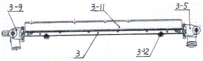
In the figure, 1-column; 2-a workbench; 3-a core; 3-1-left water chamber; 3-2-water chamber; 3-3-standing plate; 3-4-sponge strips; 3-5-right water chamber; 3-6-sealing gasket; 3-7-dust cover; 3-8-buckle plate; 3-9-water discharging switch; 3-10-glib talker; 3-11-side plate protection pad; 3-12-spring protection clip; 4-a compaction block; 5-cylinder mounting plate; 6-pressing the ball screw at the rear end; 7-fixing the plate I; 8, a compaction cylinder; 9-upper beam; 9-1-lower beam; 9-2-oblique beam; 10-a power-off brake; 11-a brake mounting plate; 12-a nut seat; 13-a nut; 14-ball screw; 15-a support seat; 16-cushion blocks; 17-fixing a second plate; 18-a suction cup type magnet; 19-a linear guide rail II; 20-a second sliding block; 21-a guide rail pad; 22-a first slide block; 23-a linear guide rail I; 24-guide shaft.
Detailed Description
In the embodiment, referring to attached figures 1-6, a pressing device on a water chamber pressing machine is characterized in that 3 symmetrical upright posts 1 are fixed on two sides above a workbench 2, a lower cross beam 9-1 is fixed on the top ends of the upright posts 1 in the forward direction, a bracket with a trapezoidal side surface is fixed above the lower cross beam 9-1, and the bracket is composed of an upper cross beam 9 and an oblique beam 9-2. A vehicle radiator is placed on a workbench 2, the upper surface and the lower surface of a main body core 3 of the vehicle radiator are fixed with main boards 3-3, a water chamber 3-2 is fixed on the upper main board 3-3, the left end of the water chamber 3-2 is provided with a right water chamber 3-5, the right end of the water chamber 3-2 is provided with a dustproof cover 3-7, the intersection of the main board 3-3 and the right water chamber 3-5 is sealed by a sponge pad 3-4 and a rubber sealing pad 3-6, a side board protection pad 3-11 is arranged at the back of the core 3, and two side surfaces of the core 3 are respectively provided with a buckle plate 3-8 and a spring protection clamp 3-12. A left water chamber 3-1, an oil nozzle 3-10 and a water discharge switch 3-9 are arranged below the core 3. A second fixing plate 17 is arranged below an upper cross beam 9 at the upper end of each upright post 1 through a cushion block 16, vertical parallel guide rail pads 21 are fixed below the second fixing plates 17, two parallel first sliding blocks 22 are fixed below the second fixing plates 17 on the inner sides of the two vertical guide rail pads 21, the first sliding blocks 22 are arranged in two parallel linear guide rails 23, the linear guide rails 23 are fixed at the left end and the right end of the cylinder mounting plate 5, 4 cylinder mounting plates 5 are arranged in parallel, a first fixing plate 7 is fixedly arranged above each cylinder mounting plate 5, and a compression cylinder 8 is fixed above the first fixing plate 7. A compressing block 4 is arranged on the periphery of a piston rod of the compressing cylinder 8, a second sliding block 20 is fixedly arranged on the lower end face of the guide rail pad 21, and the second sliding block 20 is arranged in the second parallel linear guide rail 19. The second slide block 20 is connected with the ball screw 6 at the rear end and moves left and right in the second linear guide rail 19. A brake mounting plate 11 is fixedly arranged below the cylinder mounting plate 5, a power-off brake 10 is arranged on the automatic device mounting plate 11, and a guide shaft 24 is arranged at the center of the power-off brake 10. A nut seat 12 is installed on the inner side face of the right guide rail pad 21, a nut 13 is installed in the nut seat 12, the nut 13 is in threaded connection with a ball screw 14, and the ball screw 14 drives the nut seat 12 to move left and right. The nut seat 12 is provided with a sucker type magnet 18, two ends of the ball screw 14 are arranged below the second fixing plate 17 through a supporting seat 15, and the upper part of the second fixing plate 17 is arranged below the upper cross beam 9 through a cushion block 16. Referring to the attached figure 7, a PLC control module in a control schematic diagram of a pressing device on a water chamber pressing machine controls a power supply and is connected with and controls an emergency stop signal to be effective; the emergency stop signal controls emergency stop and system self-check, the system self-check is connected with the emergency stop signal and is used for abnormal pre-tightening of the power-off brake when the emergency stop signal is effective, the system self-check is connected with the control frequency converter, the frequency converter is connected with the servo motor, and the servo motor is connected with the ball screw to control the operation. The ball screw connection control sucking disc electro-magnet and the outage formula stopper circular telegram, sucking disc electro-magnet and the operation of the outage formula stopper circular telegram connection control ball screw, ball makes one of them arrival preset position of compressing tightly the cylinder and connect control sucking disc electro-magnet and the outage formula stopper outage, sucking disc electro-magnet and the outage formula stopper outage connection control compress tightly the cylinder work and compress tightly the hydroecium and make a plurality of cylinders that compress tightly reach preset position, connect and get back to converter and servo motor, when compressing tightly the cylinder and reacing preset position, sucking disc electro-magnet and the outage formula stopper outage connection control ball screw operation.
The working principle of the invention is as follows: in the previous process, the main board 3-6 and the core 3 are welded together; placing an upper sealing gasket 3-1 and a water chamber 3-2 in a groove of a main board 3-6, driving a rear end to press a ball screw 6 to rotate by a servo motor, integrally moving a radiator core 3, the sealing gasket 3-1 and the water chamber 3-6 to the left below an upper pressing device through the movement of a second sliding block 20 in a second linear guide rail 19, and positioning and stopping the left side of the core 3; the servo motor drives the ball screw 14 to rotate, the ball screw 14 drives the nut seat 12, the brake mounting plate 11, the sucker type electromagnet 18 and the nut 13 to move along the first linear guide rail 23 to reach a hauling position, namely the position of the cylinder mounting plate 5 assembled by the air cylinder pressing 8-1 is pressed, the sucker type electromagnet 18 is powered on, the power-off brake 10 on the cylinder mounting plate 5 is powered on, the guide shaft 24 is loosened, the cylinder mounting plate 5 and the sucker type electromagnet 18 are attracted, the ball screw 14 continues to rotate, the sucker type electromagnet 18, the cylinder mounting plate 5 and the pressing air cylinder 8 are driven to reach a preset position along the first linear guide rail 23, the sucker type electromagnet 18 is powered off, the cylinder mounting plate 5 is loosened, the power-off brake 10 is powered off, the guide shaft 24 is locked to press the position of the air cylinder 8, and the position. Repeating the above process to adjust the positions of other pressing cylinders 8, inputting compressed air into the pressing cylinders 8 after all the pressing cylinders 8 reach the preset positions, driving the pressing block 4 to move downwards by the piston rod, and pressing the water chamber 3-2 into the grooves of the main board 3-6 on the radiator to complete the water chamber pressing process.
Claims (1)
1. A pressing device on a water chamber pressing machine comprises upright columns (1), a workbench (2), a pressing cylinder (8), an upper cross beam (9), a lower cross beam (9-1), a power-off brake (10), a nut seat (12) and nuts (13), and is characterized in that a frame with a trapezoidal upper end side is formed by the upright columns (1), the upper cross beam (9), the lower cross beam (9-1) and oblique beams (9-2), the frame is arranged above the workbench (2), a vehicle radiator is arranged above the workbench (2), a second fixing plate (17) is arranged below the upper cross beam (9) at the upper end of each upright column (1) through a cushion block (16), vertical parallel guide rail pads (21) are fixed below the second fixing plates (17) at the inner sides of the two vertical guide rail pads (21), two parallel first sliding blocks (22) are fixed below the second fixing plates (17) at the inner sides of the two vertical guide rail pads (21), the first sliding blocks (22) are arranged in the first parallel linear guide rails (23), the first linear guide rails (23) are fixed at the left end and the right end of the cylinder mounting plate (5), the cylinder mounting plates (5) are arranged in parallel, a first fixing plate (7) is fixedly arranged above each cylinder mounting plate (5), the pressing cylinder (8) is fixed on the first fixing plate (7), a pressing block (4) is arranged on the periphery of a piston rod of the pressing cylinder (8), a second sliding block (20) is fixed on the lower end face of the guide rail pad (21), the second sliding block (20) is arranged in the second parallel linear guide rails (19), the second sliding block (20) is connected with a rear end pressing ball screw (6) and moves left and right in the second linear guide rails (19), a brake mounting plate (11) is fixed below the cylinder mounting plates (5), a power-off brake (10) is arranged on the brake mounting plate (11), and a guide shaft (24) is arranged at the center of the power-off brake (10), a nut seat (12) is installed on the inner side face of the right guide rail pad (21), a nut (13) is installed in the nut seat (12), the nut (13) is in threaded connection with a ball screw (14), the ball screw (14) drives the nut seat (12), a sucker type magnet (18) is arranged on the nut seat (12), and two ends of the ball screw (14) are installed below a second fixing plate (17) through supporting seats (15).
Priority Applications (1)
| Application Number | Priority Date | Filing Date | Title |
|---|---|---|---|
| CN202010749498.7A CN111843440A (en) | 2020-07-30 | 2020-07-30 | Upper pressing device of water chamber pressing machine |
Applications Claiming Priority (1)
| Application Number | Priority Date | Filing Date | Title |
|---|---|---|---|
| CN202010749498.7A CN111843440A (en) | 2020-07-30 | 2020-07-30 | Upper pressing device of water chamber pressing machine |
Publications (1)
| Publication Number | Publication Date |
|---|---|
| CN111843440A true CN111843440A (en) | 2020-10-30 |
Family
ID=72946124
Family Applications (1)
| Application Number | Title | Priority Date | Filing Date |
|---|---|---|---|
| CN202010749498.7A Pending CN111843440A (en) | 2020-07-30 | 2020-07-30 | Upper pressing device of water chamber pressing machine |
Country Status (1)
| Country | Link |
|---|---|
| CN (1) | CN111843440A (en) |
Citations (7)
| Publication number | Priority date | Publication date | Assignee | Title |
|---|---|---|---|---|
| SU893500A1 (en) * | 1979-01-09 | 1981-12-30 | Днепропетровский Филиал Проектно-Конструкторского Технологического Института Автоматизации И Механизации | Stand for assembling articles |
| JP2004017054A (en) * | 2002-06-12 | 2004-01-22 | Aida Eng Ltd | Blank floating device |
| CN101600336A (en) * | 2008-06-04 | 2009-12-09 | 鸿富锦精密工业(深圳)有限公司 | Radiator assembling fixture |
| CN102990343A (en) * | 2012-12-11 | 2013-03-27 | 纳百川控股有限公司 | Novel single-tooth pressing machine |
| CN106914552A (en) * | 2015-12-25 | 2017-07-04 | 上海德朗汽车散热器制造有限公司 | A kind of manual buckle machine of automobile radiators |
| CN110253894A (en) * | 2018-03-12 | 2019-09-20 | 常州朗伯文智能装备有限公司 | A kind of automation vibration friction welding machine |
| CN212526761U (en) * | 2020-07-30 | 2021-02-12 | 辽宁东升精机有限公司 | Upper pressing device of water chamber pressing machine |
-
2020
- 2020-07-30 CN CN202010749498.7A patent/CN111843440A/en active Pending
Patent Citations (7)
| Publication number | Priority date | Publication date | Assignee | Title |
|---|---|---|---|---|
| SU893500A1 (en) * | 1979-01-09 | 1981-12-30 | Днепропетровский Филиал Проектно-Конструкторского Технологического Института Автоматизации И Механизации | Stand for assembling articles |
| JP2004017054A (en) * | 2002-06-12 | 2004-01-22 | Aida Eng Ltd | Blank floating device |
| CN101600336A (en) * | 2008-06-04 | 2009-12-09 | 鸿富锦精密工业(深圳)有限公司 | Radiator assembling fixture |
| CN102990343A (en) * | 2012-12-11 | 2013-03-27 | 纳百川控股有限公司 | Novel single-tooth pressing machine |
| CN106914552A (en) * | 2015-12-25 | 2017-07-04 | 上海德朗汽车散热器制造有限公司 | A kind of manual buckle machine of automobile radiators |
| CN110253894A (en) * | 2018-03-12 | 2019-09-20 | 常州朗伯文智能装备有限公司 | A kind of automation vibration friction welding machine |
| CN212526761U (en) * | 2020-07-30 | 2021-02-12 | 辽宁东升精机有限公司 | Upper pressing device of water chamber pressing machine |
Similar Documents
| Publication | Publication Date | Title |
|---|---|---|
| CN212526761U (en) | Upper pressing device of water chamber pressing machine | |
| CN216354550U (en) | Be applied to sealed rigging equipment who glues of battery case butyl | |
| CN111843440A (en) | Upper pressing device of water chamber pressing machine | |
| CN213672114U (en) | Hardware precision cutting device | |
| CN211805663U (en) | Positioning mechanism | |
| CN112209076A (en) | Paste dress conveyor and subsides dress equipment | |
| CN219113166U (en) | Vibrating mirror laser welding equipment for battery module | |
| CN217002552U (en) | One drags four screens laminating pressurize tools | |
| CN111370746A (en) | End face pressing device of module battery | |
| CN202668126U (en) | Fixture for machining positioning hole of motor cylinder cover | |
| CN111822783B (en) | Aluminum honeycomb laminated plate cutting machine | |
| CN212287155U (en) | Polishing device for upper and lower surfaces of automobile axle housing plate | |
| CN209380973U (en) | A kind of buck device of wood-based plate | |
| CN112743413A (en) | High-precision intelligent toughened glass edge grinding equipment and working method thereof | |
| CN206811235U (en) | A kind of full-automatic door and window angle-code saw | |
| CN213290184U (en) | Quick adjustable fixture for machining | |
| CN220636910U (en) | Movable pressing device for forklift rear tire assembly | |
| CN216031935U (en) | Multilayer vulcanizing press | |
| CN209140283U (en) | Join device automatic setup system in double plate crawler belts | |
| CN204954297U (en) | Elasticity side bearing dismounting device | |
| CN214310615U (en) | Automatic plug device for EOL (Ethernet over coax) test of calipers of automobile brake system | |
| CN221366010U (en) | Pressing machine for assembling silencing sheet in brake block | |
| CN109911801B (en) | Lower part side jacking device | |
| CN220772530U (en) | Spring life-span check out test set | |
| CN221809013U (en) | Slip table formula new energy automobile battery package friction stir welding frock |
Legal Events
| Date | Code | Title | Description |
|---|---|---|---|
| PB01 | Publication | ||
| PB01 | Publication | ||
| SE01 | Entry into force of request for substantive examination | ||
| SE01 | Entry into force of request for substantive examination |