Sewage pretreatment method and device
Technical Field
The invention relates to the technical field of sewage treatment, in particular to a sewage pretreatment method and a sewage pretreatment device.
Background
The sewage treatment is a process for purifying sewage to meet the water quality requirement of discharging the sewage into a certain water body or reusing the sewage, and generally comprises the following three steps: the first treatment is mechanical treatment, the second treatment is biological treatment, the third treatment is advanced treatment of sewage, the degree of treatment is different according to the needs, and filtration and precipitation are the most important treatment steps at first, and the subsequent treatment effect can be directly related.
But sewage treatment plant on the existing market is when deposiing, and the sediment is easy to accumulate for just need concentrated treatment at every other dead time, and the treatment complex operation is time-consuming, has influenced sewage treatment's efficiency.
Disclosure of Invention
The invention provides a sewage pretreatment device, which can effectively solve the problems that when the sewage treatment device provided by the background technology is used for sedimentation, sediment is easy to accumulate, so that centralized treatment is needed at intervals, the treatment operation is complicated and time-consuming, and the sewage treatment efficiency is influenced.
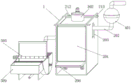
In order to achieve the purpose, the invention provides the following technical scheme: the device comprises a support frame, wherein a precipitation assembly is arranged in the support frame, and the precipitation assembly comprises a precipitation tank, a water inlet pipe, a guide port, a water outlet pipe, a sewage outlet, a sewage discharge pipe, a rubber pipe, a support column, a movable plate, a seal ring, a support spring, a limit strip hole and a positioning pin;
the settling tank is movably arranged in a support frame, a water inlet pipe is arranged at the top end of the side surface of the settling tank in a penetrating manner, a guide port is arranged at the position, corresponding to the water inlet pipe, of the support frame, a water outlet pipe is arranged at the middle part of the other side surface of the settling tank in a penetrating manner, a drain outlet is arranged at one end of the bottom surface of the settling tank, a drain pipe is connected to the bottom end of the drain outlet, a rubber pipe is arranged at the position of the two ends of the bottom surface of the settling tank, which are far away from the drain outlet, in a penetrating manner, two support columns are slidably arranged in the rubber pipe, the top ends of the two support columns are respectively;
the top surface of the settling box is provided with a limiting strip, and a limiting strip hole is formed in the side surface of the supporting frame corresponding to the limiting strip.
Preferably, the included angle between the sewage discharge pipe and the ground is 45 degrees, and the sewage discharge pipe is embedded in the sewage discharge port.
Preferably, the bottom end and the bottom end of the rubber pipe are both bonded with sealing rings, and the sealing rings are matched with the supporting columns.
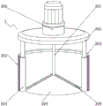
Preferably, the top end of the settling tank is provided with a dosing assembly, and the dosing assembly comprises a dosing hole, a storage box, a silica gel ring, an electric push rod, a cover plate, a bulk cargo motor, a connecting shaft, a conical cover and a material guide plate;
the utility model discloses a solar cell, including setting up deposit box top, containing box top, silica gel ring, electric push rod input and outer power output end electrical property, the setting up deposit box top corresponds medicine hole position department and installs the containing box, containing box top edge position department installs the silica gel circle, electric push rod is all installed to containing box both sides inner wall, electric push rod input links to each other with outer power output end electrical property, two electricity push rod top is connected respectively in apron bottom surface both ends, apron top surface mid-mounting has bulk cargo motor, bulk cargo motor output shaft end runs through the apron and is connected with the connecting axle, the conical cover is.
Preferably, the diameter of the medicine adding hole is equal to that of the bottom surface of the conical cover, and the diameter of the storage box is larger than that of the medicine adding hole.
Preferably, the top end of the water inlet pipe is connected with a water inlet assembly, and the water inlet assembly comprises a bottom shell, an inner shell, a magnetic stripe, a connecting ring, a top shell and a connecting pipe;
the inlet tube top is run through and is installed in drain pan bottom middle part, the drain pan cup joints in the inner shell outside, the inside even magnetic stripe of inlaying of inner shell, the drain pan top is rotated and is installed the go-between, the go-between passes through the screw thread and links to each other in top shell bottom, the top shell top is rotated and is installed the connecting pipe.
Preferably, thread grooves are uniformly formed in the edge of the bottom end of the top shell.
Preferably, the inner shell is provided with an embedding groove corresponding to the magnetic strip, and the magnetic strip is embedded in the embedding groove.
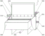
Preferably, one side of the sewage discharge pipe is connected with a deslagging assembly, and the deslagging assembly comprises a semi-cylindrical barrel, an arc-shaped filter screen, a return pipe, a porous rotating pipe, a scraper, a return pipe, a water pump, a driving motor, a discharge pipe, a collecting box and a claw;
the semi-cylinder section of thick bamboo is placed in support frame one side, semi-cylinder section of thick bamboo internally mounted has the arc filter screen, semi-cylinder section of thick bamboo top is rotated and is installed porous rotating tube, the equal fixed mounting in porous rotating tube both sides has the scraper blade, the back flow is connected to porous rotating tube one end, the back flow mid-mounting has the water pump, semi-cylinder section of thick bamboo bottom is connected to the back flow bottom, driving motor is connected to porous rotating tube one end, discharge pipe is connected at semi-cylinder section of thick bamboo bottom mid-mounting, the collecting box is installed to semi-cylinder section of thick bamboo one side, the hook has all been welded at collecting box one side both ends, water.
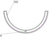
Preferably, the two ends of the arc-shaped filter screen are welded with the supporting nets close to the top end and the middle part of the bottom surface of the semi-cylindrical barrel, and the length of the supporting net is equal to that of the semi-cylindrical barrel.
Compared with the prior art, the invention has the beneficial effects that: the invention has scientific and reasonable structure and safe and convenient use;
1. be provided with the sediment subassembly, the inside back of sewage entering settling cask is depositd, and the water on sediment back top layer is discharged along the outlet pipe, and the deposit constantly accumulates, and settling cask weight increases extracts the locating pin, and the settling cask moves down along the support column, support column jack-up fly leaf this moment, and the fly leaf slope spills the drain, and the little sewage of deposit intercommunication this moment passes through the drain and discharges, and the back of discharging, supporting spring promote settling cask reconversion, and it is convenient fast to clear up.
2. Be provided with and add the medicine subassembly, at the inside medicament that adds of containing box, when needing to add the medicine, move down through electric push rod pulling apron, the bell no longer seals the hole of adding medicine, and bulk cargo motor rotates this moment, and under the centrifugal force effect, the medicament flies apart along the bell top surface, and it is even convenient to add the medicine.
3. Be provided with into water subassembly, sewage can be earlier through the subassembly of intaking before getting into the setting tank, and when sewage passes through the spheroid that drain pan and top shell are constituteed, ferromagnetic substance can be adsorbed by the magnetic stripe, blocks in the pipeline and causes the jam when preventing to get into the setting tank inside, and rotates the go-between and can open the clearance, and is convenient to use.
4. Be provided with the slagging-off subassembly, inside the sewage on the setting tank upper strata flowed into the arc filter screen of a semi-cylindrical section of thick bamboo, accessible driving motor drove the scraper blade and rotates, clears up the floater that is stopped by the arc filter screen, promotes debris to the collecting box in, and takes out partly filterable sewage through the water pump, discharges through the porous rotating tube outside, washes the scraper blade, prevents to influence the scraper blade, and the clearance is convenient.
5. Spacing is extracted to the accessible, pulls down the setting tank, through rotating the go-between, separately drain pan and topshell to take off porous rotating tube and collecting box, dismantle the slagging-off subassembly, install is dismantled easily to each part of device, is convenient for overhaul and clear up, and it is more convenient to use.
To sum up, get rid of ferromagnetic substance through the subassembly that intakes, prevent to block, deposit the subassembly cooperation and add the medicine subassembly and detach the precipitate, and deposit the subassembly clearance extremely convenient, the floater of arc filter screen top surface is detached to the rethread deslagging subassembly to accomplish the preliminary treatment process of sewage, the clearance is simple and convenient, easily operation has made things convenient for subsequent water treatment.
Drawings
The accompanying drawings, which are included to provide a further understanding of the invention and are incorporated in and constitute a part of this specification, illustrate embodiments of the invention and together with the description serve to explain the principles of the invention and not to limit the invention.
In the drawings:
FIG. 1 is a schematic structural view of the present invention;
FIG. 2 is a schematic view of the installation structure of the settling tank of the present invention;
FIG. 3 is a schematic view of the installation structure of the storage box of the present invention;
FIG. 4 is a schematic structural view of a water intake assembly of the present invention;
FIG. 5 is a schematic view of the construction of the deslagging assembly of the present invention;
FIG. 6 is a schematic view of the mounting structure of the support net of the present invention;
reference numbers in the figures: 1. a support frame;
2. a precipitation assembly; 201. a settling tank; 202. a water inlet pipe; 203. a guide port; 204. a water outlet pipe; 205. a sewage draining outlet; 206. a blow-off pipe; 207. a rubber tube; 208. a support pillar; 209. a movable plate; 210. a seal ring; 211. a support spring; 212. a limiting strip; 213. limiting strip holes; 214. positioning pins;
3. a dosing assembly; 301. a medicine adding hole; 302. a storage box; 303. a silica gel ring; 304. an electric push rod; 305. a cover plate; 306. a bulk motor; 307. a connecting shaft; 308. a conical cover; 309. a material guide plate;
4. a water intake assembly; 401. a bottom case; 402. an inner shell; 403. a magnetic strip; 404. a connecting ring; 405. a top shell; 406. a connecting pipe;
5. a deslagging assembly; 501. a semi-cylindrical barrel; 502. an arc-shaped filter screen; 503. a porous rotating tube; 504. a squeegee; 505. a return pipe; 506. a water pump; 507. a drive motor; 508. a discharge pipe; 509. a collection box; 510. a hook claw;
6. and supporting the net.
Detailed Description
The preferred embodiments of the present invention will be described in conjunction with the accompanying drawings, and it will be understood that they are described herein for the purpose of illustration and explanation and not limitation.
Example (b): as shown in fig. 1-6, the present invention provides a technical solution of a sewage pretreatment device, which comprises a support frame 1, wherein a precipitation assembly 2 is arranged inside the support frame 1, and the precipitation assembly 2 comprises a precipitation tank 201, a water inlet pipe 202, a guide port 203, a water outlet pipe 204, a sewage outlet 205, a sewage outlet pipe 206, a rubber pipe 207, a support column 208, a movable plate 209, a seal ring 210, a support spring 211, a limit strip 212, a limit strip hole 213 and a positioning pin 214;
the settling tank 201 is movably arranged inside the support frame 1, the top end of the side surface of the settling tank 201 is provided with a water inlet pipe 202 in a penetrating way, the support frame 1 is provided with a guide port 203 corresponding to the water inlet pipe 202, the middle part of the other side surface of the settling tank 201 is provided with a water outlet pipe 204 in a penetrating way, one end of the bottom surface of the settling tank 201 is provided with a sewage outlet 205, the bottom end of the sewage outlet 205 is connected with a sewage discharge pipe 206, the included angle between the sewage discharge pipe 206 and the ground is 45 degrees, the sewage discharge pipe 206 is embedded in the sewage outlet 205, the sewage discharge pipe 206 is convenient to install, the positions of the two ends of the bottom surface of the settling tank 201, which are far away from the sewage outlet 205, are provided with a rubber pipe 207 in a penetrating way, a support column 208 is slidably arranged inside the rubber pipe 207, the outer edge of the movable plate 209 is sleeved with a sealing ring 210, supporting springs 211 are uniformly distributed on the bottom surface of the settling tank 201, and positioning pins 214 are installed at the top ends of the supporting columns 208 in a penetrating manner;
the top surface of the settling tank 201 is provided with a limit strip 212, and the side surface of the support frame 1 corresponding to the limit strip 212 is provided with a limit strip hole 213.
The top end of the settling tank 201 is provided with a dosing assembly 3, and the dosing assembly 3 comprises a dosing hole 301, a containing tank 302, a silica gel ring 303, an electric push rod 304, a cover plate 305, a bulk material motor 306, a connecting shaft 307, a conical cover 308 and a material guide plate 309;
deposit 201 top corresponds the hole 301 position department of adding medicine and installs containing box 302, containing box 302 top border position department installs silica gel circle 303, electric push rod 304 is all installed to containing box 302 both sides inner wall, electric push rod 304 input and outer power output end electric connection, two electric push rod 304 tops are connected respectively in apron 305 bottom surface both ends, apron 305 top surface mid-mounting has bulk material motor 306, bulk material motor 306 output shaft end runs through apron 305 and is connected with connecting axle 307, conical cover 308 is connected to connecting axle 307 bottom, add the diameter that the hole 301 diameter equals the conical cover 308 bottom surface of adding medicine, containing box 302 diameter is greater than the hole 301 diameter of adding medicine, be convenient for conical cover 308 seals and add medicine hole 301, guide plate 309 is all installed to conical cover 308 top surface both sides.
The top end of the water inlet pipe 202 is connected with a water inlet assembly 4, and the water inlet assembly 4 comprises a bottom shell 401, an inner shell 402, a magnetic strip 403, a connecting ring 404, a top shell 405 and a connecting pipe 406;
inlet tube 202 top is run through and is installed in drain pan 401 bottom middle part, drain pan 401 cup joints in the inner shell 402 outside, the inside even embedding of inner shell 402 has magnetic stripe 403, inner shell 402 corresponds magnetic stripe 403 department and has seted up and inlay the groove, magnetic stripe 403 inlays in inlaying inslot portion, be convenient for install magnetic stripe 403, drain pan 401 top is rotated and is installed go-between 404, go-between 404 links to each other in top shell 405 bottom through the screw thread, top shell 405 top is rotated and is installed connecting pipe 406, top shell 405 bottom edge has evenly seted up the thread groove, be convenient for top shell 405 and go-between 404.
One side of the sewage discharge pipe 206 is connected with a deslagging assembly 5, and the deslagging assembly 5 comprises a semi-cylindrical barrel 501, an arc-shaped filter screen 502, a return pipe 505, a porous rotating pipe 503, a scraper 504, the return pipe 505, a water pump 506, a driving motor 507, a discharge pipe 508, a collecting box 509 and a claw 510;
a semi-cylindrical section of thick bamboo 501 is placed in support frame 1 one side, semi-cylindrical section of thick bamboo 501 internally mounted has arc filter screen 502, arc filter screen 502 both ends are close to semi-cylindrical section of thick bamboo 501 top and bottom surface middle part and all have welded supporting network 6, supporting network 6 length equals semi-cylindrical section of thick bamboo 501 length, be convenient for support arc filter screen 502, semi-cylindrical section of thick bamboo 501 top is rotated and is installed porous rotating tube 503, porous rotating tube 503 both sides equal fixed mounting has scraper blade 504, back flow pipe 505 is connected to porous rotating tube 503 one end, back flow pipe 505 mid-mounting has water pump 506, the semi-cylindrical section of thick bamboo 501 bottom is connected to back flow pipe 505 bottom, driving motor 507 is connected to porous rotating tube 503 one end, semi-cylindrical section of thick bamboo 501 bottom mid-connection discharge pipe 508, collecting box 509 is installed to semi-cylindrical section of thick bamboo 501 one.
The working principle and the using process of the invention are as follows: sewage firstly enters a spherical cavity formed by the bottom shell 401 and the top shell 405 through the connecting pipe 406, ferromagnetic substances are adsorbed by the magnetic strip 403, and the sewage is prevented from being blocked in a pipeline when entering the interior of the settling tank 201;
then sewage enters the settling tank 201 through the water inlet pipe 202 to be settled, water on the top layer in the settling tank 201 is discharged along the water outlet pipe 204 after settlement, sediment is accumulated continuously, the weight of the settling tank 201 is increased, the positioning pin 214 is pulled out, the settling tank 201 moves downwards along the supporting column 208, the supporting spring 211 contracts, the supporting column 208 jacks up the movable plate 209 at the moment, due to the extrusion of sediment on the top surface of the movable plate 209, only one side bottom surface of the movable plate 209 is jacked up, the movable plate 209 inclines to leak out the sewage outlet 205, at the moment, the sediment is communicated with a small amount of sewage to slide along the inclined movable plate 209, the top surface of the movable plate 209 is made of polytetrafluoroethylene and is not easy to adhere dirt, the sediment is discharged along the sewage outlet 205, after discharge, the settling tank 201 becomes light, the supporting spring 211 restores to the original state to push the settling tank 201 to return to the original position, thereby improving the overall sewage treatment efficiency;
when the medicine is required to be added, the electric push rod 304 pushes up the cover plate 305, the medicine can be added through a gap between the containing box 302 and the cover plate 305, the bottom end of the conical cover 308 is flush with the ground of the medicine adding hole 301 to seal the medicine adding hole 301, when the medicine is required to be added, the electric push rod 304 pulls the cover plate 305 to move downwards, the conical cover 308 moves downwards, the medicine adding hole 301 is not closed any more, the bulk material motor 306 rotates at the moment, the medicine slides along the material guide plate 309 on the top surface of the conical cover 308 under the action of centrifugal force, and the medicine scatters and is uniform and convenient to add the;
sewage on the upper layer of the settling tank 201 flows into the arc-shaped filter screen 502 of the semi-cylindrical barrel 501, the scraper 504 can be driven to rotate by the driving motor 507, floaters blocked by the arc-shaped filter screen 502 are cleaned, sundries are pushed into the collecting tank 509, a part of filtered sewage is pumped out by the water pump 506 and is discharged through the outer side of the porous rotating pipe 503, the scraper 504 is washed, the impurities are prevented from being adhered to the surface of the scraper 504 after being dried to influence the scraper 504, and the claw 510 is taken down together with the collecting tank 509, so that the cleaning is convenient;
dismantle setting tank 201, through rotating go-between 404, part drain pan 401 and top shell 405, dismantle inner shell 402 to take off porous rotating tube 503 and collecting box 509, dismantle slagging-off subassembly 5, the installation is dismantled easily to each part of device, is convenient for overhaul and clear up, and it is more convenient to use.
To sum up, detach ferromagnetic substance through water intaking subassembly 4, prevent to block, deposit subassembly 2 cooperation and add medicine subassembly 3 and detach the precipitate, and deposit subassembly 2 clearance is very convenient, and the floater of arc filter screen 502 top surface is detached to rethread slagging-off subassembly 5 to accomplish the preliminary treatment process of sewage, the clearance is simple and convenient, easily the operation has made things convenient for subsequent water treatment.
Finally, it should be noted that: although the present invention has been described in detail with reference to the foregoing embodiments, it will be apparent to those skilled in the art that changes may be made in the embodiments and/or equivalents thereof without departing from the spirit and scope of the invention. Any modification, equivalent replacement, or improvement made within the spirit and principle of the present invention should be included in the protection scope of the present invention.