CN111715747A - Bending device is tailor to heat preservation aluminium sheet metal - Google Patents
Bending device is tailor to heat preservation aluminium sheet metal Download PDFInfo
- Publication number
- CN111715747A CN111715747A CN202010532606.5A CN202010532606A CN111715747A CN 111715747 A CN111715747 A CN 111715747A CN 202010532606 A CN202010532606 A CN 202010532606A CN 111715747 A CN111715747 A CN 111715747A
- Authority
- CN
- China
- Prior art keywords
- cutting
- belt pulley
- compression roller
- bending device
- pressing
- Prior art date
- Legal status (The legal status is an assumption and is not a legal conclusion. Google has not performed a legal analysis and makes no representation as to the accuracy of the status listed.)
- Pending
Links
Images


Classifications
-
- B—PERFORMING OPERATIONS; TRANSPORTING
- B21—MECHANICAL METAL-WORKING WITHOUT ESSENTIALLY REMOVING MATERIAL; PUNCHING METAL
- B21D—WORKING OR PROCESSING OF SHEET METAL OR METAL TUBES, RODS OR PROFILES WITHOUT ESSENTIALLY REMOVING MATERIAL; PUNCHING METAL
- B21D5/00—Bending sheet metal along straight lines, e.g. to form simple curves
- B21D5/14—Bending sheet metal along straight lines, e.g. to form simple curves by passing between rollers
-
- B—PERFORMING OPERATIONS; TRANSPORTING
- B21—MECHANICAL METAL-WORKING WITHOUT ESSENTIALLY REMOVING MATERIAL; PUNCHING METAL
- B21D—WORKING OR PROCESSING OF SHEET METAL OR METAL TUBES, RODS OR PROFILES WITHOUT ESSENTIALLY REMOVING MATERIAL; PUNCHING METAL
- B21D5/00—Bending sheet metal along straight lines, e.g. to form simple curves
- B21D5/002—Positioning devices
-
- B—PERFORMING OPERATIONS; TRANSPORTING
- B23—MACHINE TOOLS; METAL-WORKING NOT OTHERWISE PROVIDED FOR
- B23P—METAL-WORKING NOT OTHERWISE PROVIDED FOR; COMBINED OPERATIONS; UNIVERSAL MACHINE TOOLS
- B23P23/00—Machines or arrangements of machines for performing specified combinations of different metal-working operations not covered by a single other subclass
- B23P23/04—Machines or arrangements of machines for performing specified combinations of different metal-working operations not covered by a single other subclass for both machining and other metal-working operations
Abstract
The invention relates to a cutting and bending device, in particular to a cutting and bending device for an insulating aluminum sheet. The invention aims to provide a cutting and bending device for an insulation aluminum thin plate, which can cut quickly and bend automatically. The utility model provides a bending device is tailor to heat preservation aluminium sheet, including: a frame; the motor is fixedly arranged on the frame; the first belt pulley is fixedly connected to the output end of the motor; the connecting plates are fixedly arranged on two side surfaces of the rack; the second belt pulley is rotatably connected with the connecting plate close to one side of the motor; the V-shaped belt is wound on the first belt pulley and the second belt pulley; the second compression roller is rotatably connected with the connecting plates on the two sides; and the third compression roller is rotatably connected with the connecting plates at the two sides and is close to the second compression roller, and one end of the third compression roller penetrates through the connecting plates and is fixedly connected with the second belt pulley. According to the invention, the thin aluminum plate can be rapidly cut by the cutting device, the cutting along the track can prevent bending, and the bending is driven by the motor, so that the aluminum plate can be automatically compressed during bending, and the operation is convenient and rapid for one person.
Description
Technical Field
The invention relates to a cutting and bending device, in particular to a cutting and bending device for an insulating aluminum sheet.
Background
The heat preservation aluminum sheet is light and convenient to process, and some heat preservation box shells can be made of the heat preservation aluminum sheet.
Before manufacturing, the sheet-shaped heat-insulating aluminum thin plate needs to be cut to a suitable length and then bent, and the bent heat-insulating aluminum thin plate is convenient to weld.
At present heat preservation aluminium sheet metal at first needs the manual work to use the cutter to cut open aluminum plate when bending, then inserts aluminum plate alone and three and the long gyro wheel between hand aluminum plate, another individual rethread wave the long gyro wheel of bending, makes aluminum plate process, the completion of bending, this kind of mode of bending needs two people simultaneous operation, and the manual work uses the cutter cutting to appear cutting curved easily moreover.
Therefore, the cutting and bending device for the heat-preservation aluminum thin plate, which can cut quickly and bend automatically, is needed to be provided.
Disclosure of Invention
(1) Technical problem to be solved
The invention aims to overcome the defects that two persons are required to operate simultaneously and cutting and bending are easy to occur when a cutter is used manually in the conventional bending mode, and the technical problem to be solved by the invention is to provide the cutting and bending device for the heat-insulating aluminum thin plate, which can cut quickly and bend automatically.
(2) Technical scheme
In order to solve the technical problem, the invention provides a cutting and bending device for an insulating aluminum sheet, which comprises:
a frame;
the motor is fixedly arranged on the frame;
the first belt pulley is fixedly connected to the output end of the motor;
the connecting plates are fixedly arranged on two side surfaces of the rack;
the second belt pulley is rotatably connected with the connecting plate close to one side of the motor;
the V-shaped belt is wound on the first belt pulley and the second belt pulley;
the second compression roller is rotatably connected with the connecting plates on the two sides;
the third compression roller is rotatably connected with the connecting plates on the two sides and is close to the second compression roller, and one end of the third compression roller penetrates through the connecting plates and is fixedly connected with the second belt pulley;
the connecting rods are respectively and fixedly connected to the end parts of the connecting plates at the two sides;
the movable seats are respectively and movably inserted into the connecting rods;
the load spring is sleeved on the connecting rod, and one end of the load spring is connected with the movable seat;
and the first compression roller is rotatably connected to the movable seats on the two sides.
Preferably, the device further comprises a conveying device, and the conveying device is arranged on one side face of the rack.
Preferably, the transfer device comprises:
the rotating seat is fixedly arranged on one side surface of the rack and is far away from the connecting plates on the two sides;
the conveying roller is rotatably connected to the rotating seat;
the rocker penetrates through the rotating seat and is installed at one end of the conveying roller;
and the workbench is arranged on one side of the conveying roller, is connected with the rack and is positioned between the conveying roller and the third press roller.
Preferably, the cutting device is arranged above the workbench and connected with the workbench.
Preferably, the cutting device comprises:
the rail frame is fixedly arranged on the workbench;
the cutter holder is arranged in the track frame in a sliding mode;
the pulling rod is fixedly arranged on one side surface of the cutter holder;
the cutting knife is fixedly arranged at one end of the knife holder.
Preferably, the V-shaped belt tensioning device further comprises a tensioning device, wherein the tensioning device is arranged on the connecting plate and is in contact with the V-shaped belt.
Preferably, the tensioner comprises:
the fixed block is fixedly arranged on one side surface of the connecting plate;
the spring seat is connected to the fixed block in a sliding manner through a sliding rod on the spring seat;
the tension wheel is rotationally connected to one side of the spring seat and is contacted with the V belt;
the jacking spring is sleeved on the sliding rod of the spring seat, and one end of the jacking spring is connected with the fixed block.
Preferably, the device further comprises a pressing device, and the pressing device is arranged on the workbench.
Preferably, the pressing device comprises:
the pressing brackets are fixedly connected to two sides of the workbench respectively;
the pressing frames are respectively connected to one end of the pressing bracket;
the sliding plate is connected with the pressing frame in a sliding manner;
the follower rollers are rotatably connected with the sliding plates on the two sides;
and the elastic piece is arranged in the pressing frame, one end of the elastic piece is fixedly connected to the pressing frame, and the other end of the elastic piece is fixedly connected to the sliding plate.
(3) Advantageous effects
1. The invention can rapidly cut the thin aluminum plate through the cutting device, and can prevent bending by cutting along the track.
2. The bending machine is driven by the motor to bend, and the aluminum plate can be automatically compressed during bending, so that the bending machine can be operated by one person conveniently and quickly.
3. The invention can transmit materials by shaking, and can compress the aluminum plate by the compressing device during material transmission, thereby preventing errors from occurring during cutting of the aluminum plate.
Drawings
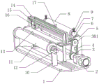
Fig. 1 is a schematic perspective view of a first embodiment of the present invention.
Fig. 2 is a schematic perspective view of a second embodiment of the present invention.
Fig. 3 is a schematic perspective view of the tensioner of the present invention.
Fig. 4 is a schematic perspective view of the compressing device of the present invention.
The labels in the figures are: 1-a rack, 2-a motor, 3-a belt pulley I, 301-a belt pulley II, a 4-V belt, 5-a connecting plate, 6-a connecting rod, 7-a movable seat, 8-a press roller I, 801-a press roller II, 802-a press roller III, 9-a loading spring, 10-a rotating seat, 11-a conveying roller, 12-a rocker, 13-a workbench, 14-a track frame, 15-a tool holder, 16-a cutting knife, 17-a pulling rod, 18-a fixed block, 19-a spring seat, 191-a slide rod, 20-a tensioning wheel, 21-a jacking spring, 22-a compaction support, 23-a compaction frame, 24-a sliding plate, 25-a follower roller and 26-an elastic part.
Detailed Description
The invention is further described below with reference to the figures and examples.
Example 1
A cutting and bending device for a heat-insulating aluminum sheet comprises a rack 1, a motor 2, a first belt pulley 3, a connecting plate 5, a second belt pulley 301, a V belt 4, a second compression roller 801, a third compression roller 802, a connecting rod 6, a movable seat 7, a first compression roller 8 and a load spring 9, wherein the motor 2 is fixedly arranged on the left side of the top of the rack 1, the first belt pulley 3 is connected to the output end of the motor 2 through a coupler, the two connecting plates 5 are respectively and fixedly arranged on the left side and the right side above the rack 1, the left connecting plate 5 is close to the output end of the motor 2, the second belt pulley 301 is rotatably connected to the left side surface of the left connecting plate 5, the V belt 4 is wound on the first belt pulley 3 and the second belt pulley 301, two ends of the second compression roller 801 and the third compression roller 802 are rotatably connected to the inner side surfaces of the connecting plates 5 on the two sides, the third, the top of both sides connecting plate 5 all is connected with connecting rod 6, and two sliding seat 7 movable sleeve respectively are on the connecting rod 6 of both sides, and load spring 9 embolias on connecting rod 6, and the bottom is connected with sliding seat 7, and the top is connected with connecting rod 6 top, and 8 both ends of compression roller rotate to be connected in both sides sliding seat 7.
Before bending, firstly, insert aluminium sheet one end into compression roller 8, between two compression rollers 801 and three compression rollers 802, load spring 9 can exert pressure for compression roller 8, make compression roller 8 compress tightly aluminium sheet, make aluminium sheet and compression roller 8, two compression rollers 801 and three compression rollers 802 paste tightly, start-up motor 2 corotation this moment and bend the work, belt pulley 3 on the motor 2 drives two 301 corotation of belt pulley through V area 4, belt pulley two 301 drives three compression rollers 802 and rotates, three compression rollers 802 drive aluminium sheet and remove, bending when aluminium sheet passes through compression roller 8, two compression rollers 801 and three compression rollers 802 is accomplished, close motor 2.
Example 2
On the basis of embodiment 1, as shown in fig. 2, the device further comprises a conveying device, and the conveying device is arranged on one side surface of the rack 1.
Conveyer is including swivel mount 10, transfer roller 11, rocker 12 and workstation 13, swivel mount 10 fixed mounting is in the top rear side of frame 1, and the both ends of transfer roller 11 are rotated and are connected in the both sides wall of swivel mount 10, and rocker 12 passes the left end rigid coupling of swivel mount 10 left side wall and transfer roller 11, and workstation 13 fixed connection is on frame 1, and it is located between transfer roller 11 and the three 802 of compression roller, and workstation 13 is the same with transfer roller 11's height.
And the cutting device is positioned above the workbench 13 and connected with the workbench 13.
The cutting device comprises a track frame 14, a cutter holder 15, a cutting knife 16 and a pulling rod 17, wherein the track frame 14 is fixedly arranged at the top of the workbench 13, the cutter holder 15 is slidably arranged in the track frame 14, the pulling rod 17 is fixedly arranged on the left side surface of the cutter holder 15, and the cutting knife 16 is fixedly arranged at the lower end of the cutter holder 15.
The conveying device is used for conveying the aluminum plates.
Can place the workstation 13 on with on the transfer roller 11 to aluminum plate before bending aluminum plate, when conveying aluminum plate to compression roller 8, two 801 of compression roller and three 802 of compression roller, manual corotation rocker 12, rocker 12 drive the transfer roller 11 rotation, and transfer roller 11 drives aluminum plate and removes to compression roller 8, two 801 of compression roller and three 802 directions of compression roller.
The cutting device is used for cutting the aluminum plate.
When aluminum plate needs to be cut off, the aluminum plate on the workbench 13 is placed, the cutting position is moved to the position below the cutting knife 16, the cutting knife 16 is placed on the right side of the aluminum plate at the moment, then the pulling rod 17 is manually pulled to move leftwards, and the pulling rod 17 drives the cutting knife 16 to cut the aluminum plate.
Example 3
On the basis of the embodiment 2, as shown in fig. 2-4, a tensioning device is further included, and the tensioning device is arranged on the connecting plate 5 and is in contact with the V-belt 4.
The tensioning device comprises a fixed block 18, a spring seat 19, a tensioning wheel 20 and a jacking spring 21, the fixed block 18 is fixedly installed on the left side face of the left connecting plate 5, the spring seat 19 is connected to the fixed block 18 in a sliding mode through a sliding rod 191 on the spring seat 19, the tensioning wheel 20 is connected to the left side of the spring seat 19 in a rotating mode, the tensioning wheel 20 is in contact with the V-shaped belt 4, the jacking spring 21 is sleeved on the sliding rod 191 of the spring seat 19, the rear end of the jacking spring is connected with the front side of the fixed block.
The device further comprises a pressing device, and the pressing device is arranged on the workbench 13.
The pressing device comprises pressing supports 22, pressing frames 23, sliding plates 24, follower rollers 25 and elastic pieces 26, wherein the two pressing supports 22 are fixedly connected to the left side and the right side of the top of the workbench 13 respectively and are located at the rear sides of the track frames 14, the pressing frames 23 are fixedly connected to the rear ends of the pressing supports 22 respectively, the sliding plates 24 penetrate through the bottoms of the pressing frames 23 and are connected with the pressing frames 23 in a sliding mode, the two ends of the follower rollers 25 are rotatably connected to the lower portions of the sliding plates 24 on the two sides, the elastic pieces 26 are arranged in the pressing frames 23, the top ends of the elastic pieces are fixedly connected to the inner top of the pressing frames 23, and.
The tensioning device is used for enabling the V belt 4 to be compressed tightly, and the V belt 4 is prevented from being loosened excessively, so that the first belt pulley 3 cannot drive the second belt pulley 301 to rotate through the V belt 4.
The tension device pushes the spring seat 19 through the pushing spring 21, so that the tension wheel 20 on the spring seat 19 presses the V belt 4.
The pressing device is used for pressing the aluminum plate on the conveying device, so that the aluminum plate can be prevented from inclining and shifting during cutting, and the conveying is more convenient.
The pressing device pushes the sliding plate 24 through the elastic member 26 so that the follower roller 25 connected to the sliding plate 24 presses the aluminum plate.
The above examples are merely representative of preferred embodiments of the present invention, and the description thereof is more specific and detailed, but not to be construed as limiting the scope of the present invention. It should be noted that, for those skilled in the art, various changes, modifications and substitutions can be made without departing from the spirit of the present invention, and these are all within the scope of the present invention. Therefore, the protection scope of the present patent shall be subject to the appended claims.
Claims (9)
1. The utility model provides a bending device is tailor to heat preservation aluminium sheet, which characterized in that, including:
a frame (1);
the motor (2) is fixedly arranged on the frame (1);
the first belt pulley (3) is fixedly connected to the output end of the motor (2);
the connecting plates (5) are fixedly arranged on two side surfaces of the rack (1);
the second belt pulley (301) is rotatably connected to the connecting plate (5) close to one side of the motor (2);
the V-shaped belt (4) is wound on the first belt pulley (3) and the second belt pulley (301);
the second compression roller (801) is rotatably connected to the connecting plates (5) on the two sides;
the third compression roller (802) is rotatably connected with the connecting plates (5) on the two sides and close to the second compression roller (801), and one end of the third compression roller penetrates through the connecting plates (5) to be fixedly connected with the second belt pulley (301);
the connecting rods (6) are respectively and fixedly connected with the end parts of the connecting plates (5) at the two sides;
the movable seats (7) are respectively and movably inserted into the connecting rods (6);
the load spring (9) is sleeved on the connecting rod (6), and one end of the load spring is connected with the movable seat (7);
and the first compression roller (8) is rotatably connected with the movable seats (7) on the two sides.
2. The cutting and bending device for the heat-preservation aluminum sheets as claimed in claim 1, further comprising a conveying device, wherein the conveying device is arranged on one side surface of the rack (1).
3. The cutting and bending device for the heat-preservation aluminum sheet as claimed in claim 2, wherein the conveying device comprises:
the rotating seat (10) is fixedly arranged on one side surface of the rack (1) and is far away from the connecting plates (5) on the two sides;
a conveying roller (11) rotatably connected to the rotary base (10);
the rocker (12) passes through the rotating seat (10) and is arranged at one end of the conveying roller (11);
and the workbench (13) is arranged on one side of the conveying roller (11), is connected with the rack (1), and is positioned between the conveying roller (11) and the third compression roller (802).
4. The cutting and bending device for the heat-preservation aluminum sheets as claimed in claim 3, further comprising a cutting device, wherein the cutting device is located above the workbench (13) and connected with the workbench (13).
5. The cutting and bending device for the heat-preservation aluminum sheet as claimed in claim 4, wherein the cutting device comprises:
a rail frame (14) fixedly mounted on the workbench (13);
a cutter holder (15) which is slidably mounted in the rail frame (14);
a pulling rod (17) fixedly installed on one side surface of the tool holder (15);
a cutting knife (16) fixedly arranged at one end of the cutter holder (15).
6. The cutting and bending device for the heat-preservation aluminum sheets as claimed in claim 5, further comprising a tensioning device, wherein the tensioning device is arranged on the connecting plate (5) and is in contact with the V-shaped belt (4).
7. The cutting and bending device for the heat-preservation aluminum sheet as claimed in claim 6, wherein the tensioning device comprises:
the fixing block (18) is fixedly arranged on one side surface of the connecting plate (5);
the spring seat (19) is connected to the fixed block (18) in a sliding manner through a sliding rod (191) on the spring seat;
a tension pulley (20) which is rotatably connected to one side of the spring seat (19) and is in contact with the V-belt (4);
and the jacking spring (21) is sleeved on the sliding rod (191) of the spring seat (19), and one end of the jacking spring is connected with the fixed block (18).
8. The cutting and bending device for the heat-preservation aluminum sheets as claimed in claim 7, further comprising a pressing device, wherein the pressing device is arranged on the workbench (13).
9. The cutting and bending device for the heat-preservation aluminum sheet according to claim 8, wherein the pressing device comprises:
the pressing supports (22) are respectively and fixedly connected to two sides of the workbench (13);
the pressing frames (23) are respectively connected to one end of the pressing bracket (22);
a slide plate (24) slidably connected to the pressing frame (23);
a follower roller (25) rotatably connected to the sliding plates (24) on both sides;
and the elastic piece (26) is arranged in the pressing frame (23), one end of the elastic piece is fixedly connected to the pressing frame (23), and the other end of the elastic piece is fixedly connected to the sliding plate (24).
Priority Applications (1)
| Application Number | Priority Date | Filing Date | Title |
|---|---|---|---|
| CN202010532606.5A CN111715747A (en) | 2020-06-12 | 2020-06-12 | Bending device is tailor to heat preservation aluminium sheet metal |
Applications Claiming Priority (1)
| Application Number | Priority Date | Filing Date | Title |
|---|---|---|---|
| CN202010532606.5A CN111715747A (en) | 2020-06-12 | 2020-06-12 | Bending device is tailor to heat preservation aluminium sheet metal |
Publications (1)
| Publication Number | Publication Date |
|---|---|
| CN111715747A true CN111715747A (en) | 2020-09-29 |
Family
ID=72566548
Family Applications (1)
| Application Number | Title | Priority Date | Filing Date |
|---|---|---|---|
| CN202010532606.5A Pending CN111715747A (en) | 2020-06-12 | 2020-06-12 | Bending device is tailor to heat preservation aluminium sheet metal |
Country Status (1)
| Country | Link |
|---|---|
| CN (1) | CN111715747A (en) |
Cited By (3)
| Publication number | Priority date | Publication date | Assignee | Title |
|---|---|---|---|---|
| CN112975354A (en) * | 2021-02-12 | 2021-06-18 | 翁晓炜 | Automatic processing device for aluminum alloy door and window tube profiles |
| CN113103287A (en) * | 2021-03-04 | 2021-07-13 | 安徽致和节能科技有限公司 | Processing device for outer wall homogeneous modified fireproof insulation board |
| CN117428503A (en) * | 2023-11-29 | 2024-01-23 | 江苏古彦铝业有限公司 | Automatic cutting machine for aluminum plate |
Citations (4)
| Publication number | Priority date | Publication date | Assignee | Title |
|---|---|---|---|---|
| CN207430977U (en) * | 2017-08-24 | 2018-06-01 | 罗田县康威金属容器科技有限公司 | A kind of veneer reeling machine |
| CN208098973U (en) * | 2018-02-08 | 2018-11-16 | 江苏菱坤电器工程有限公司 | A kind of electronic iron sheet circular knitting machine of water tank edge rolling |
| CN208555565U (en) * | 2018-04-24 | 2019-03-01 | 苏州硕丰精密机械有限公司 | Can automatic cut-to-length shearing three roller furling plate round machine |
| CN111229885A (en) * | 2020-01-17 | 2020-06-05 | 蔡燕 | Automatic rounding, sewing and leakage detecting integrated machine for water tank inner container of solar water heater and process thereof |
-
2020
- 2020-06-12 CN CN202010532606.5A patent/CN111715747A/en active Pending
Patent Citations (4)
| Publication number | Priority date | Publication date | Assignee | Title |
|---|---|---|---|---|
| CN207430977U (en) * | 2017-08-24 | 2018-06-01 | 罗田县康威金属容器科技有限公司 | A kind of veneer reeling machine |
| CN208098973U (en) * | 2018-02-08 | 2018-11-16 | 江苏菱坤电器工程有限公司 | A kind of electronic iron sheet circular knitting machine of water tank edge rolling |
| CN208555565U (en) * | 2018-04-24 | 2019-03-01 | 苏州硕丰精密机械有限公司 | Can automatic cut-to-length shearing three roller furling plate round machine |
| CN111229885A (en) * | 2020-01-17 | 2020-06-05 | 蔡燕 | Automatic rounding, sewing and leakage detecting integrated machine for water tank inner container of solar water heater and process thereof |
Cited By (4)
| Publication number | Priority date | Publication date | Assignee | Title |
|---|---|---|---|---|
| CN112975354A (en) * | 2021-02-12 | 2021-06-18 | 翁晓炜 | Automatic processing device for aluminum alloy door and window tube profiles |
| CN113103287A (en) * | 2021-03-04 | 2021-07-13 | 安徽致和节能科技有限公司 | Processing device for outer wall homogeneous modified fireproof insulation board |
| CN117428503A (en) * | 2023-11-29 | 2024-01-23 | 江苏古彦铝业有限公司 | Automatic cutting machine for aluminum plate |
| CN117428503B (en) * | 2023-11-29 | 2024-04-09 | 江苏古彦铝业有限公司 | Automatic cutting machine for aluminum plate |
Similar Documents
| Publication | Publication Date | Title |
|---|---|---|
| CN111715747A (en) | Bending device is tailor to heat preservation aluminium sheet metal | |
| CN111872173B (en) | Iron plate continuous bending machine | |
| CN112643120B (en) | Industrial steel pipe equidistance cutting equipment | |
| CN110525709B (en) | Fruit is wrapped with covering plastic wrap device fast | |
| CN214265723U (en) | Gummed paper is with cutting device who has protective structure | |
| CN111572098A (en) | Automatic groover of cardboard | |
| CN113443224B (en) | Sealing device for logistics packaging bags and using method thereof | |
| CN112497280B (en) | Cutting and polishing equipment for corrugated paper production | |
| CN115743703B (en) | Ultra-white embossed solar glass raw sheet packaging equipment and packaging method thereof | |
| CN113199903A (en) | Wall paper rubber coating equipment | |
| CN113879626B (en) | Automatic packing sorting device of electricity merchant commodity circulation | |
| CN112373124B (en) | Wrapping bag processing equipment | |
| CN112937156B (en) | Book gluing line | |
| CN210676756U (en) | Pipe cutting machine for wire harness production | |
| CN111791278A (en) | High-efficient cutting equipment of polytetrafluoroethylene film | |
| CN117021282A (en) | Edge sealing device for processing side edges of composite board | |
| CN113927397B (en) | Wooden decoration panel material edge trimming device for house decoration | |
| CN217992865U (en) | Automatic edge sealing equipment for moisture-proof bamboo product production | |
| CN214686693U (en) | High-temperature environment adhesive tape sucking and cutting mechanism | |
| CN114801325B (en) | Portable mounting process for cartons | |
| CN216099126U (en) | Toast bread slicing device | |
| CN217123402U (en) | Hard paper material template cutting equipment | |
| CN214561344U (en) | Feeding device of manual die-cutting machine | |
| CN212049744U (en) | Automobile sealing strip gluing equipment | |
| CN216884241U (en) | Shearing device for processing antiknock high-gram-weight paper |
Legal Events
| Date | Code | Title | Description |
|---|---|---|---|
| PB01 | Publication | ||
| PB01 | Publication | ||
| SE01 | Entry into force of request for substantive examination | ||
| SE01 | Entry into force of request for substantive examination | ||
| RJ01 | Rejection of invention patent application after publication | ||
| RJ01 | Rejection of invention patent application after publication |
Application publication date: 20200929 |