CN111702627A - Machine part equipment of polishing - Google Patents
Machine part equipment of polishing Download PDFInfo
- Publication number
- CN111702627A CN111702627A CN202010599261.5A CN202010599261A CN111702627A CN 111702627 A CN111702627 A CN 111702627A CN 202010599261 A CN202010599261 A CN 202010599261A CN 111702627 A CN111702627 A CN 111702627A
- Authority
- CN
- China
- Prior art keywords
- fixedly connected
- mounting
- motor
- installation
- screw rod
- Prior art date
- Legal status (The legal status is an assumption and is not a legal conclusion. Google has not performed a legal analysis and makes no representation as to the accuracy of the status listed.)
- Withdrawn
Links
Images


Classifications
-
- B—PERFORMING OPERATIONS; TRANSPORTING
- B24—GRINDING; POLISHING
- B24B—MACHINES, DEVICES, OR PROCESSES FOR GRINDING OR POLISHING; DRESSING OR CONDITIONING OF ABRADING SURFACES; FEEDING OF GRINDING, POLISHING, OR LAPPING AGENTS
- B24B27/00—Other grinding machines or devices
- B24B27/0076—Other grinding machines or devices grinding machines comprising two or more grinding tools
-
- B—PERFORMING OPERATIONS; TRANSPORTING
- B24—GRINDING; POLISHING
- B24B—MACHINES, DEVICES, OR PROCESSES FOR GRINDING OR POLISHING; DRESSING OR CONDITIONING OF ABRADING SURFACES; FEEDING OF GRINDING, POLISHING, OR LAPPING AGENTS
- B24B41/00—Component parts such as frames, beds, carriages, headstocks
- B24B41/007—Weight compensation; Temperature compensation; Vibration damping
-
- B—PERFORMING OPERATIONS; TRANSPORTING
- B24—GRINDING; POLISHING
- B24B—MACHINES, DEVICES, OR PROCESSES FOR GRINDING OR POLISHING; DRESSING OR CONDITIONING OF ABRADING SURFACES; FEEDING OF GRINDING, POLISHING, OR LAPPING AGENTS
- B24B41/00—Component parts such as frames, beds, carriages, headstocks
- B24B41/02—Frames; Beds; Carriages
-
- B—PERFORMING OPERATIONS; TRANSPORTING
- B24—GRINDING; POLISHING
- B24B—MACHINES, DEVICES, OR PROCESSES FOR GRINDING OR POLISHING; DRESSING OR CONDITIONING OF ABRADING SURFACES; FEEDING OF GRINDING, POLISHING, OR LAPPING AGENTS
- B24B41/00—Component parts such as frames, beds, carriages, headstocks
- B24B41/04—Headstocks; Working-spindles; Features relating thereto
-
- B—PERFORMING OPERATIONS; TRANSPORTING
- B24—GRINDING; POLISHING
- B24B—MACHINES, DEVICES, OR PROCESSES FOR GRINDING OR POLISHING; DRESSING OR CONDITIONING OF ABRADING SURFACES; FEEDING OF GRINDING, POLISHING, OR LAPPING AGENTS
- B24B41/00—Component parts such as frames, beds, carriages, headstocks
- B24B41/06—Work supports, e.g. adjustable steadies
-
- B—PERFORMING OPERATIONS; TRANSPORTING
- B24—GRINDING; POLISHING
- B24B—MACHINES, DEVICES, OR PROCESSES FOR GRINDING OR POLISHING; DRESSING OR CONDITIONING OF ABRADING SURFACES; FEEDING OF GRINDING, POLISHING, OR LAPPING AGENTS
- B24B47/00—Drives or gearings; Equipment therefor
- B24B47/22—Equipment for exact control of the position of the grinding tool or work at the start of the grinding operation
-
- B—PERFORMING OPERATIONS; TRANSPORTING
- B24—GRINDING; POLISHING
- B24B—MACHINES, DEVICES, OR PROCESSES FOR GRINDING OR POLISHING; DRESSING OR CONDITIONING OF ABRADING SURFACES; FEEDING OF GRINDING, POLISHING, OR LAPPING AGENTS
- B24B55/00—Safety devices for grinding or polishing machines; Accessories fitted to grinding or polishing machines for keeping tools or parts of the machine in good working condition
- B24B55/06—Dust extraction equipment on grinding or polishing machines
Abstract
The invention discloses a machine part polishing device, which relates to the technical field of polishing devices and comprises an installation box, wherein an L-shaped support frame is fixedly connected to one side of the installation box, an installation column is rotatably connected to one side of the top end of the L-shaped support frame, a transmission gear is fixedly sleeved on the installation column, an incomplete gear is rotatably connected to the L-shaped support frame at one side of the transmission gear, a cross-shaped installation frame is fixedly connected to the bottom of the installation column, an electric hydraulic telescopic column first polishing disc are fixedly connected to the center bottom of the cross-shaped installation frame, a sliding installation frame is arranged below a branch of the cross-shaped installation frame, a second polishing disc is arranged at one side of the sliding installation frame, transmission rods are hinged to two sides of the installation cylinder, installation rods are fixedly connected to fourth installation blocks at two sides of the installation cylinder, the end part, the clamping rod is far away from one end of the transmission rod and is fixedly connected with the second clamping plate, the device is convenient to operate and use, and the polishing efficiency is high.
Description
Technical Field
The invention relates to the technical field of polishing equipment, in particular to mechanical part polishing equipment.
Background
A grinding machine, also called a rasping machine, is widely used for finish machining and surface polishing treatment in the mold industry, in mechanical production, because the precision of machine tool equipment such as a lathe is limited, a plurality of parts still need to be ground after being processed to meet the requirements, the efficiency of the traditional grinder is low, and a common grinding device can only carry out single-side grinding on the parts, but some mechanical parts with higher process requirements need to be ground on the side surfaces, the common grinding device can not meet the requirements, only the contact surfaces of the mechanical parts and the grinding device can be changed by adjusting a clamping device to realize multi-surface grinding, the process needs to manually replace the grinding surfaces for repositioning and clamping, the grinding efficiency of the device is greatly reduced, and because the clamping mode of some devices is simple, the vibration generated by grinding can possibly cause the mechanical parts to deviate during grinding, the grinding quality of the parts cannot be guaranteed, the general clamping device needs to be adjusted manually, when the parts are ground, manual clamping operation is very inconvenient, the surfaces are changed for multiple times, and grinding is very complicated, and the practicability is low.
Disclosure of Invention
The invention provides a mechanical part polishing device, which solves the problems in the background technology.
In order to achieve the purpose, the invention provides the following technical scheme:
a machine part polishing device comprises a mounting box, wherein an L-shaped support frame is fixedly connected to one side of the mounting box, a mounting column is rotatably connected to one side of the top end of the L-shaped support frame, a transmission gear is fixedly sleeved on the mounting column, an incomplete gear is rotatably connected to the L-shaped support frame on one side of the transmission gear and is in meshing transmission connection with the transmission gear, a driving motor is fixedly connected to the top of the L-shaped support frame above a rotating shaft of the incomplete gear, an output shaft of the driving motor is fixedly connected with a rotating shaft of the incomplete gear, a cross mounting frame is fixedly connected to the bottom of the mounting column, four branches of the cross mounting frame are of a vertically through cavity structure, an electric hydraulic telescopic column is fixedly connected to the bottom of the center of the cross mounting frame, a first mounting shell is fixedly connected to the bottom of the electric hydraulic telescopic column, a first polishing disk is rotatably connected to the bottom, the output shaft of the first motor is fixedly connected with the rotating shaft of the first polishing disc.
As a preferable technical scheme of the invention, a branch of the cross mounting frame is rotationally connected with a first screw rod, one side of the cross mounting frame at one axial side of the first screw rod is fixedly connected with a second motor, an output shaft of the second motor is fixedly connected with the first screw rod, a first mounting block is sleeved on the first screw rod in a threaded manner, the bottom of the first mounting block is fixedly connected with a sliding mounting frame, a through groove is arranged on the sliding mounting frame, the second screw rod is rotationally connected in the through groove, a third motor is fixedly connected in the sliding mounting frame above one axial side of the second screw rod, an output shaft of the third motor is fixedly connected with the second screw rod, a second mounting block is sleeved on the second screw rod in a threaded manner, one side of the second mounting block passes through the through groove and extends to one side of the sliding mounting frame, the end part of the second mounting block is fixedly connected with a second mounting shell, one side of the second mounting shell is rotationally connected with a second polishing, an output shaft of the fourth motor is fixedly connected with a rotating shaft of the second polishing disc.
According to a preferable technical scheme of the invention, a bearing groove is arranged above the installation box below the cross-shaped installation frame, two sides of the bottom of the bearing groove are fixedly connected with T-shaped columns, the T-shaped columns are slidably sleeved with a support plate, the T-shaped columns below the support plate are sleeved with damping springs, the support plate is fixedly connected with support columns, the upper ends of the support columns penetrate through the bearing groove and extend into the bearing groove, the top of the support columns is fixedly connected with a carrying plate, and a clamping device is arranged on the carrying plate.
As a preferred technical scheme of the invention, the bottom parts of the bearing grooves on two sides of the supporting plate are fixedly connected with supporting rods, the bottom ends of the supporting rods penetrate through the top wall of the mounting box and extend into the mounting box, the bottom ends of the supporting rods are hinged with a scissor type telescopic frame, a third screw rod is rotatably connected in the mounting box below the scissor type telescopic frame, one end of the third screw rod is fixedly sleeved with a first gear, the mounting box above the first gear is rotatably connected with a second gear, a fifth motor is fixedly connected on the outer side wall of the mounting box on one side of a rotating shaft of the second gear, an output shaft of the fifth motor is fixedly connected with a rotating shaft of the second gear, a third mounting block is sleeved on the third screw rod in a threaded manner, and the third mounting.
As a preferred technical scheme of the invention, the clamping device comprises an installation cylinder, the installation cylinder is a cavity structure with two through surfaces, the installation cylinder is rotatably connected with a fourth lead screw, a sixth motor is fixedly connected to the outer side wall of the installation cylinder on one axial side of the fourth lead screw, the output shaft of the sixth motor is fixedly connected with the fourth lead screw, a fourth installation block is sleeved on the fourth lead screw in a threaded manner, two sides of the fourth installation block penetrate through the side wall of the installation cylinder and extend to one side of the installation cylinder, the end part of the fourth installation block is hinged with a transmission rod, an installation rod is fixedly connected to the fourth installation block on two sides of the installation cylinder, one side of the installation rod, which is far away from the fourth installation block, extends to one side of the installation cylinder, and the end part of.
As a preferable technical scheme, the carrying plates on two sides of the mounting cylinder are rotatably connected with clamping rods, one ends of the clamping rods are hinged with the transmission rod, one ends of the clamping rods, far away from the transmission rod, are fixedly connected with a second clamping plate, and a part body is arranged between the first clamping plate and the second clamping plate.
As a preferred technical scheme of the invention, the bearing grooves on the two sides of the carrying plate are movably connected with a recovery box, the recovery box is fixedly connected with a collection net, the bottom of the bearing groove below the recovery box is fixedly connected with a fan, and an air inlet pipe of the fan penetrates through the bottom of the bearing groove and extends into the recovery box.
The invention has the following advantages: the first polishing disc and the second polishing disc are arranged below the cross-shaped mounting frame, the mounting column with the transmission gear intermittently rotates under the drive of the incomplete gear, the cross-shaped mounting frame below the mounting column is further driven to intermittently rotate, the second polishing disc on one side of the sliding mounting frame intermittently rotates, all-dimensional polishing on the side face of the mechanical part is realized, compared with the traditional mechanical polishing device, the position of the part is not required to be repeatedly adjusted, the polishing efficiency of the mechanical part is greatly improved, the clamping device is arranged on the object carrying plate, the fourth screw rod rotates under the drive of the sixth motor to drive the fourth mounting block to move, the clamping rod is driven to rotate under the action of the transmission rod, meanwhile, the mounting rod on the fourth mounting block moves to one side of the part body, and the first clamping plate and the second clamping plate simultaneously clamp three faces of the mechanical part, compare in driven manual clamping device, trilateral centre gripping make machine part's fixed more stable, effectually prevent the part when polishing, because the skew of the position that vibrations produced, machine part's the quality of polishing has been improved, and drive disposable centre gripping through the motor, it is more convenient to operate, simultaneously through setting up damping spring on the T shape post in backup pad below, can effectual buffering carry the thing board and polish the vibrations that make the production, make the device whole work more stable, the practicality is better.
Drawings
FIG. 1 is a schematic structural diagram of a main body of a machine part grinding apparatus.
Fig. 2 is a schematic structural diagram of a cross-shaped mounting frame in the machine part grinding equipment.
Fig. 3 is a schematic structural view of a clamping device in the machine part grinding apparatus.
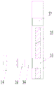
Fig. 4 is a schematic side sectional view of a slide mount in a machine part grinding apparatus.
FIG. 5 is a schematic view showing the construction of a driving gear and a partial gear in a machine part grinding apparatus.
In the figure: 1. installing a box; 2. an L-shaped support frame; 3. a sliding mount; 4. a cross mounting bracket; 401. a first lead screw; 402. a first mounting block; 403. a second motor; 5. an incomplete gear; 6. a drive motor; 7. mounting a column; 8. a transmission gear; 9. an electro-hydraulic telescopic column; 10. a first mounting case; 11. a first motor; 12. a first abrasive disc; 13. a through groove; 14. a second sanding disc; 15. a part body; 16. a clamping device; 161. mounting the cylinder; 162. a fourth screw rod; 163. a sixth motor; 164. a transmission rod; 165. a fourth mounting block; 166. a clamping rod; 167. mounting a rod; 168. a second clamping plate; 169. a first clamping plate; 17. a bearing groove; 18. a support bar; 19. a scissor type telescopic frame; 20. a third screw rod; 21. a third mounting block; 22. a loading plate; 23. a support pillar; 24. a support plate; 25. a damping spring; 26. a T-shaped column; 27. a recycling bin; 28. collecting a net; 29. a fan; 30. a second gear; 31. a first gear; 32. a fifth motor; 33. a second mounting block; 34. a second mounting case; 35. a second lead screw; 36. a fourth motor; 37. a third motor.
Detailed Description
The preferred embodiments of the present invention will be described in conjunction with the accompanying drawings, and it will be understood that they are described herein for the purpose of illustration and explanation and not limitation.
It should be noted that the terms "center", "upper", "lower", "left", "right", "vertical", "horizontal", "inner", "outer", etc. indicate orientations or positional relationships based on the orientations or positional relationships shown in the drawings, and are only for convenience in describing the present invention and simplifying the description, but do not indicate or imply that the referred devices or elements must have a specific orientation, be constructed in a specific orientation, and be operated, and thus, should not be construed as limiting the present invention.
Example 1
Referring to fig. 1-5, a machine part polishing device comprises a mounting box 1, wherein an L-shaped support frame 2 is fixedly connected to one side of the mounting box 1, an installation column 7 is rotatably connected to one side of the top end of the L-shaped support frame 2, a transmission gear 8 is fixedly sleeved on the installation column 7, an incomplete gear 5 is rotatably connected to the L-shaped support frame 2 on one side of the transmission gear 8, the incomplete gear 5 is in meshing transmission connection with the transmission gear 8, a driving motor 6 is fixedly connected to the top of the L-shaped support frame 2 above the rotating shaft of the incomplete gear 5, an output shaft of the driving motor 6 is fixedly connected to the rotating shaft of the incomplete gear 5, a cross-shaped mounting frame 4 is fixedly connected to the bottom of the installation column 7, four branches of the cross-shaped mounting frame 4 are of a vertically through cavity structure, an electric hydraulic telescopic column 9 is fixedly connected to the center bottom, the bottom of the first mounting shell 10 is rotatably connected with a first polishing disc 12, a first motor 11 is fixedly connected in the first mounting shell 10 above the rotating shaft of the first polishing disc 12, and the output shaft of the first motor 11 is fixedly connected with the rotating shaft of the first polishing disc 12.
A first screw rod 401 is rotatably connected in a branch of the cross mounting frame 4, one side of the cross mounting frame 4 at one axial side of the first screw rod 401 is fixedly connected with a second motor 403, an output shaft of the second motor 403 is fixedly connected with the first screw rod 401, a first mounting block 402 is sleeved on the first screw rod 401 in a threaded manner, the bottom of the first mounting block 402 is fixedly connected with a sliding mounting frame 3, a through groove 13 is formed in the sliding mounting frame 3, a second screw rod 35 is rotatably connected in the through groove 13, a third motor 37 is fixedly connected in the sliding mounting frame 3 above one axial side of the second screw rod 35, an output shaft of the third motor 37 is fixedly connected with the second screw rod 35, a second mounting block 33 is sleeved on the second screw rod 35 in a threaded manner, one side of the second mounting block 33 passes through the through groove 13 and extends to one side of the sliding mounting frame 3, the end part of the second mounting block is fixedly connected with a second mounting, a fourth motor 36 is fixedly connected in the second mounting shell 34 on one side of the rotating shaft of the second polishing disc 14, and an output shaft of the fourth motor 36 is fixedly connected with the rotating shaft of the second polishing disc 14.
The utility model discloses a supporting device, including cross mounting bracket 4, install bin 1, backup pad 24, damping spring 25, fixed connection support column 23, support column 23 upper end pass bearing groove 17 on the backup pad 24, and extend to in bearing groove 17, and top fixed connection carries thing board 22, carries and sets up clamping device 16 on the thing board 22 that the installation box 1 top of cross mounting bracket 4 below is equipped with bearing groove 17, and bearing groove 17 bottom both sides fixed connection T shape post 26, and the slip cup joints backup pad 24 on the T shape post 26, cup joints damping spring 25 on the T shape post 26 of backup pad 24 below, fixed.
The bottom of the bearing groove 17 on two sides of the supporting plate 24 is fixedly connected with a supporting rod 18, the bottom end of the supporting rod 18 penetrates through the top wall of the installation box 1 and extends into the installation box 1, the bottom end of the supporting rod is hinged with a scissors type telescopic frame 19, a third screw rod 20 is rotatably connected in the installation box 1 below the scissors type telescopic frame 19, one end of the third screw rod 20 is fixedly sleeved with a first gear 31, the installation box 1 above the first gear 31 is rotatably connected with a second gear 30, the outer side wall of the installation box 1 on one side of a rotating shaft of the second gear 30 is fixedly connected with a fifth motor 32, an output shaft of the fifth motor 32 is fixedly connected with the rotating shaft of the second gear 30, a third installation block 21 is sleeved on the third screw rod 20 in a threaded mode, and the third installation block.
Clamping device 16 includes a mounting cylinder 161, and the mounting cylinder 161 is the penetrating cavity structure in two sides, a fourth lead screw 162 is connected in the mounting cylinder 161 internal rotation, and fixed connection sixth motor 163 is gone up to the outside lateral wall of the mounting cylinder 161 of fourth lead screw 162 axial one side, and the output shaft and the fourth lead screw 162 fixed connection of sixth motor 163, threaded sleeve connects fourth installation piece 165 on the fourth lead screw 162, and the side wall of the mounting cylinder 161 is passed to fourth installation piece 165 both sides to extend to mounting cylinder 161 one side, and the articulated transfer line 164 of connecting of tip, fixed connection installation pole 167 is gone up to the fourth installation piece 165 of mounting cylinder 161 both sides, and fourth installation piece 165 one side is kept away from to installation pole 167 and is extended to mounting cylinder 161 one side, and the first grip block 169 of tip fixed connection.
The loading plates 22 on two sides of the mounting cylinder 161 are rotatably connected with clamping rods 166, one ends of the clamping rods 166 are hinged with the transmission rods 164, one ends of the clamping rods 166, far away from the transmission rods 164, are fixedly connected with second clamping plates 168, and part bodies 15 are arranged between the first clamping plates 169 and the second clamping plates 168.
Example 2
Referring to fig. 1 to 5, the other contents of the present embodiment are the same as embodiment 1, except that: the recycling box 27 is movably connected in the bearing grooves 17 on the two sides of the carrying plate 22, the collecting net 28 is fixedly connected in the recycling box 27, the fan 29 is fixedly connected at the bottom of the bearing groove 17 below the recycling box 27, and an air inlet pipe of the fan 29 penetrates through the bottom of the bearing groove 17 and extends into the recycling box 27.
In the implementation process of the invention, the part body 15 is placed on the object carrying plate 22, the sixth motor 163 is started to drive the fourth screw rod 162 to rotate, and further drive the fourth mounting block 165 to move, and the clamping rod 166 is driven to rotate under the action of the transmission rod 164, and simultaneously the mounting rod 167 on the fourth mounting block 165 moves towards one side of the part body 15, so that the first clamping plate 169 and the second clamping plate 168 simultaneously clamp and clamp three sides of the mechanical part, the driving motor 6 is started to drive the incomplete gear 5 to rotate, and further drive the mounting post 7 with the transmission gear 8 to intermittently rotate, and further drive the cross mounting frame 4 below to intermittently rotate, so that the second polishing disc 14 on one side of the sliding mounting frame 3 intermittently rotates, and the omnibearing polishing of the side surface of the mechanical part is realized, and the device has reasonable structural principle design and convenient operation, high grinding efficiency, good stability and high practicability.
Finally, it should be noted that: although the present invention has been described in detail with reference to the foregoing embodiments, it will be apparent to those skilled in the art that changes may be made in the embodiments and/or equivalents thereof without departing from the spirit and scope of the invention. Any modification, equivalent replacement, or improvement made within the spirit and principle of the present invention should be included in the protection scope of the present invention.
Claims (7)
1. The utility model provides a machine part equipment of polishing, includes install bin (1), its characterized in that, one side fixed connection L shape support frame (2) on install bin (1), L shape support frame (2) top one side is rotated and is connected erection column (7), fixedly cup joints drive gear (8) on erection column (7), rotates on L shape support frame (2) of drive gear (8) one side and connects incomplete gear (5), incomplete gear (5) and drive gear (8) meshing transmission are connected, L shape support frame (2) top fixed connection driving motor (6) above incomplete gear (5) pivot, the output shaft of driving motor (6) and the pivot fixed connection of incomplete gear (5), erection column (7) bottom fixed connection cross mounting bracket (4), four branches of cross mounting bracket (4) are penetrating cavity structure from top to bottom, the center bottom of the cross-shaped mounting frame (4) is fixedly connected with an electric hydraulic telescopic column (9), the bottom of the electric hydraulic telescopic column (9) is fixedly connected with a first mounting shell (10), the bottom of the first mounting shell (10) is rotatably connected with a first polishing disk (12), a first motor (11) is fixedly connected in the first mounting shell (10) above the rotating shaft of the first polishing disk (12), and the output shaft of the first motor (11) is fixedly connected with the rotating shaft of the first polishing disk (12).
2. The machine part grinding equipment according to claim 1, wherein a first screw rod (401) is rotatably connected in a branch of the cross mounting frame (4), a second motor (403) is fixedly connected to one side of the cross mounting frame (4) on one axial side of the first screw rod (401), an output shaft of the second motor (403) is fixedly connected with the first screw rod (401), a first mounting block (402) is sleeved on the first screw rod (401) in a threaded manner, a sliding mounting frame (3) is fixedly connected to the bottom of the first mounting block (402), a through groove (13) is formed in the sliding mounting frame (3), a second screw rod (35) is rotatably connected in the through groove (13), a third motor (37) is fixedly connected to the inside of the sliding mounting frame (3) above one axial side of the second screw rod (35), an output shaft of the third motor (37) is fixedly connected with the second screw rod (35), a second mounting block (33) is sleeved on the second screw rod (35) in a threaded manner, the through groove (13) is passed on one side of the second mounting block (33), the second mounting block extends to one side of the sliding mounting frame (3), the end part is fixedly connected with the second mounting shell (34), one side of the second mounting shell (34) is rotatably connected with the second polishing disc (14), the second mounting shell (34) on one side of the rotating shaft of the second polishing disc (14) is internally and fixedly connected with the fourth motor (36), and the output shaft of the fourth motor (36) is fixedly connected with the rotating shaft of the second polishing disc (14).
3. The machine part grinding equipment according to claim 2, wherein a bearing groove (17) is arranged above the installation box (1) below the cross-shaped installation rack (4), T-shaped columns (26) are fixedly connected to two sides of the bottom of the bearing groove (17), a support plate (24) is slidably sleeved on the T-shaped columns (26), damping springs (25) are sleeved on the T-shaped columns (26) below the support plate (24), support columns (23) are fixedly connected to the support plate (24), the upper ends of the support columns (23) penetrate through the bearing groove (17) and extend into the bearing groove (17), a loading plate (22) is fixedly connected to the top of the loading plate, and clamping devices (16) are arranged on the loading plate (22).
4. The machine part grinding equipment according to claim 3, wherein the bottom of the bearing groove (17) at both sides of the support plate (24) is fixedly connected with a support rod (18), the bottom end of the support rod (18) penetrates through the top wall of the installation box (1) and extends into the installation box (1), the bottom end of the support rod is hinged with a scissors type expansion bracket (19), a third screw rod (20) is rotatably connected in the installation box (1) below the scissors type expansion bracket (19), one end of the third screw rod (20) is fixedly sleeved with a first gear (31), the installation box (1) above the first gear (31) is rotatably connected with a second gear (30), a fifth motor (32) is fixedly connected on the outer side wall of the installation box (1) at one side of the rotating shaft of the second gear (30), the output shaft of the fifth motor (32) is fixedly connected with the rotating shaft of the second gear (30), and a third installation block (21) is sleeved on the third screw rod (20) in a threaded, the third mounting block (21) is hinged with the scissor type telescopic frame (19).
5. The machine part grinding equipment according to claim 4, wherein the clamping device (16) comprises a mounting cylinder (161), the mounting cylinder (161) is a hollow structure with two through surfaces, a fourth lead screw (162) is rotatably connected in the mounting cylinder (161), a sixth motor (163) is fixedly connected to the outer side wall of the mounting cylinder (161) on one axial side of the fourth lead screw (162), an output shaft of the sixth motor (163) is fixedly connected with the fourth lead screw (162), a fourth mounting block (165) is in threaded sleeve connection with the fourth lead screw (162), two sides of the fourth mounting block (165) penetrate through the side wall of the mounting cylinder (161) and extend to one side of the mounting cylinder (161), the end part of the fourth mounting block (165) is in hinged connection with a transmission rod (164), a mounting rod (167) is fixedly connected to the fourth mounting block (165) on two sides of the mounting cylinder (161), and one side of the mounting rod (167), which is far away from the fourth mounting block (165), extends to one side of the mounting cylinder (161), and the end part is fixedly connected with a first clamping plate (169).
6. The machine part grinding equipment according to claim 5, wherein the loading plates (22) on two sides of the mounting cylinder (161) are rotatably connected with clamping rods (166), one ends of the clamping rods (166) are hinged with the transmission rod (164), one ends of the clamping rods (166) far away from the transmission rod (164) are fixedly connected with second clamping plates (168), and the part body (15) is arranged between the first clamping plates (169) and the second clamping plates (168).
7. The machine part grinding equipment according to claim 4 or 5, wherein the carrying grooves (17) on both sides of the carrying plate (22) are movably connected with a recovery box (27), a collection net (28) is fixedly connected in the recovery box (27), the bottom of the carrying groove (17) below the recovery box (27) is fixedly connected with a fan (29), and an air inlet pipe of the fan (29) penetrates through the bottom of the carrying groove (17) and extends into the recovery box (27).
Priority Applications (1)
| Application Number | Priority Date | Filing Date | Title |
|---|---|---|---|
| CN202010599261.5A CN111702627A (en) | 2020-06-28 | 2020-06-28 | Machine part equipment of polishing |
Applications Claiming Priority (1)
| Application Number | Priority Date | Filing Date | Title |
|---|---|---|---|
| CN202010599261.5A CN111702627A (en) | 2020-06-28 | 2020-06-28 | Machine part equipment of polishing |
Publications (1)
| Publication Number | Publication Date |
|---|---|
| CN111702627A true CN111702627A (en) | 2020-09-25 |
Family
ID=72543698
Family Applications (1)
| Application Number | Title | Priority Date | Filing Date |
|---|---|---|---|
| CN202010599261.5A Withdrawn CN111702627A (en) | 2020-06-28 | 2020-06-28 | Machine part equipment of polishing |
Country Status (1)
| Country | Link |
|---|---|
| CN (1) | CN111702627A (en) |
Cited By (10)
| Publication number | Priority date | Publication date | Assignee | Title |
|---|---|---|---|---|
| CN112517475A (en) * | 2020-11-13 | 2021-03-19 | 向明朗 | Magnetic ring cleaning device with collection function |
| CN112872961A (en) * | 2021-02-06 | 2021-06-01 | 德化县丽德家居用品有限公司 | Multi-functional deburring polisher for ceramic machining |
| CN113001377A (en) * | 2021-02-27 | 2021-06-22 | 焦文彬 | Protective cover processing mechanism of video monitor |
| CN113084657A (en) * | 2021-03-29 | 2021-07-09 | 安徽华之邦信息科技有限公司 | Adjustable grinding machanism of computer machine case is exclusively used in |
| CN113245867A (en) * | 2021-06-11 | 2021-08-13 | 山东奥扬新能源科技股份有限公司 | Clamping tool for processing air faucet of bottle body |
| CN113635479A (en) * | 2021-08-19 | 2021-11-12 | 六安市叶集区聚诚高分子材料有限公司 | Engineering plastic cutting machine and using method thereof |
| CN114986322A (en) * | 2022-08-01 | 2022-09-02 | 江苏欧远地板有限公司 | Timber grinding device |
| CN115042074A (en) * | 2022-08-16 | 2022-09-13 | 江苏瑞仕达电气设备有限公司 | Surface polishing device for finish machining of bus duct |
| CN115229635A (en) * | 2021-01-28 | 2022-10-25 | 马鞍山市华茂机械科技有限公司 | Operation method of machining device for ring-shaped part production |
| CN115229635B (en) * | 2021-01-28 | 2024-04-19 | 马鞍山市华茂机械科技有限公司 | Operation method of processing device for producing annular piece |
Citations (5)
| Publication number | Priority date | Publication date | Assignee | Title |
|---|---|---|---|---|
| EP0845326A1 (en) * | 1996-11-28 | 1998-06-03 | Witte-Metallwaren GmbH | Apparatus for grinding or polishing floors or surfaces |
| WO2012025329A1 (en) * | 2010-08-26 | 2012-03-01 | Robert Bosch Gmbh | Hand-held machine tool |
| CN207788499U (en) * | 2017-12-25 | 2018-08-31 | 重庆长松科技发展有限公司 | A kind of motorcycle accessories grinding device with cleaning function |
| CN208841138U (en) * | 2018-08-28 | 2019-05-10 | 天津明日宇航新材料科技有限公司 | A kind of efficient aluminium sheet grinding device |
| CN110405604A (en) * | 2019-08-21 | 2019-11-05 | 盐城市高跃机械有限公司 | A kind of auto parts and components grinding device |
-
2020
- 2020-06-28 CN CN202010599261.5A patent/CN111702627A/en not_active Withdrawn
Patent Citations (5)
| Publication number | Priority date | Publication date | Assignee | Title |
|---|---|---|---|---|
| EP0845326A1 (en) * | 1996-11-28 | 1998-06-03 | Witte-Metallwaren GmbH | Apparatus for grinding or polishing floors or surfaces |
| WO2012025329A1 (en) * | 2010-08-26 | 2012-03-01 | Robert Bosch Gmbh | Hand-held machine tool |
| CN207788499U (en) * | 2017-12-25 | 2018-08-31 | 重庆长松科技发展有限公司 | A kind of motorcycle accessories grinding device with cleaning function |
| CN208841138U (en) * | 2018-08-28 | 2019-05-10 | 天津明日宇航新材料科技有限公司 | A kind of efficient aluminium sheet grinding device |
| CN110405604A (en) * | 2019-08-21 | 2019-11-05 | 盐城市高跃机械有限公司 | A kind of auto parts and components grinding device |
Cited By (10)
| Publication number | Priority date | Publication date | Assignee | Title |
|---|---|---|---|---|
| CN112517475A (en) * | 2020-11-13 | 2021-03-19 | 向明朗 | Magnetic ring cleaning device with collection function |
| CN115229635A (en) * | 2021-01-28 | 2022-10-25 | 马鞍山市华茂机械科技有限公司 | Operation method of machining device for ring-shaped part production |
| CN115229635B (en) * | 2021-01-28 | 2024-04-19 | 马鞍山市华茂机械科技有限公司 | Operation method of processing device for producing annular piece |
| CN112872961A (en) * | 2021-02-06 | 2021-06-01 | 德化县丽德家居用品有限公司 | Multi-functional deburring polisher for ceramic machining |
| CN113001377A (en) * | 2021-02-27 | 2021-06-22 | 焦文彬 | Protective cover processing mechanism of video monitor |
| CN113084657A (en) * | 2021-03-29 | 2021-07-09 | 安徽华之邦信息科技有限公司 | Adjustable grinding machanism of computer machine case is exclusively used in |
| CN113245867A (en) * | 2021-06-11 | 2021-08-13 | 山东奥扬新能源科技股份有限公司 | Clamping tool for processing air faucet of bottle body |
| CN113635479A (en) * | 2021-08-19 | 2021-11-12 | 六安市叶集区聚诚高分子材料有限公司 | Engineering plastic cutting machine and using method thereof |
| CN114986322A (en) * | 2022-08-01 | 2022-09-02 | 江苏欧远地板有限公司 | Timber grinding device |
| CN115042074A (en) * | 2022-08-16 | 2022-09-13 | 江苏瑞仕达电气设备有限公司 | Surface polishing device for finish machining of bus duct |
Similar Documents
| Publication | Publication Date | Title |
|---|---|---|
| CN111702627A (en) | Machine part equipment of polishing | |
| CN111360645A (en) | Building material grinding device | |
| CN112828697A (en) | Pipe fitting equipment of polishing of adaptable different pipe diameters size | |
| CN216633722U (en) | Workpiece chamfering and polishing equipment | |
| CN112192419B (en) | Sheet metal polishing robot convenient to operate for machining | |
| CN212095584U (en) | Laser crystal processing is with upset burnishing device | |
| CN112548137A (en) | Device and method for simultaneously processing multiple holes | |
| CN211516927U (en) | Grinding device is used in main shaft processing | |
| CN219465628U (en) | Rotary shaft end processing device | |
| CN211192949U (en) | Bearing turning equipment | |
| CN202479953U (en) | Flange plane grinding device | |
| CN112405280A (en) | Manual cleaning and polishing platform for mechanical parts | |
| CN219212632U (en) | Grinding disc device for metal part machining | |
| CN216327242U (en) | Based on automation equipment is with adjustable grinding machine | |
| CN214237560U (en) | High-speed railway spare part grinding device | |
| CN220806898U (en) | Thread fixing tool for small flat grinding | |
| CN215788785U (en) | Plunger type ball head grinder machine tool | |
| CN108857742A (en) | A kind of curved surfaces grinding device with diamond grinding head | |
| CN220388997U (en) | Grinding tool in machine tool shell | |
| CN216830077U (en) | Marble renovates with quick deburring device | |
| CN219234987U (en) | Grinding wheel mill convenient to replace | |
| CN216883325U (en) | Machining grinding device | |
| CN211891465U (en) | A numerical control lathe for processing ceramic | |
| CN211565427U (en) | Grinding device for machining | |
| CN213672973U (en) | Automatic rotor automatic combination machine capable of being automatically positioned and assembled |
Legal Events
| Date | Code | Title | Description |
|---|---|---|---|
| PB01 | Publication | ||
| PB01 | Publication | ||
| SE01 | Entry into force of request for substantive examination | ||
| SE01 | Entry into force of request for substantive examination | ||
| WW01 | Invention patent application withdrawn after publication |
Application publication date: 20200925 |
|
| WW01 | Invention patent application withdrawn after publication |