CN111700579A - Introducer for tracheal cannula - Google Patents
Introducer for tracheal cannula Download PDFInfo
- Publication number
- CN111700579A CN111700579A CN202010514550.0A CN202010514550A CN111700579A CN 111700579 A CN111700579 A CN 111700579A CN 202010514550 A CN202010514550 A CN 202010514550A CN 111700579 A CN111700579 A CN 111700579A
- Authority
- CN
- China
- Prior art keywords
- introducer
- proximal
- section
- tracheal tube
- segment
- Prior art date
- Legal status (The legal status is an assumption and is not a legal conclusion. Google has not performed a legal analysis and makes no representation as to the accuracy of the status listed.)
- Pending
Links
Images


Classifications
-
- A—HUMAN NECESSITIES
- A61—MEDICAL OR VETERINARY SCIENCE; HYGIENE
- A61M—DEVICES FOR INTRODUCING MEDIA INTO, OR ONTO, THE BODY; DEVICES FOR TRANSDUCING BODY MEDIA OR FOR TAKING MEDIA FROM THE BODY; DEVICES FOR PRODUCING OR ENDING SLEEP OR STUPOR
- A61M16/00—Devices for influencing the respiratory system of patients by gas treatment, e.g. mouth-to-mouth respiration; Tracheal tubes
- A61M16/04—Tracheal tubes
- A61M16/0488—Mouthpieces; Means for guiding, securing or introducing the tubes
-
- A—HUMAN NECESSITIES
- A61—MEDICAL OR VETERINARY SCIENCE; HYGIENE
- A61B—DIAGNOSIS; SURGERY; IDENTIFICATION
- A61B1/00—Instruments for performing medical examinations of the interior of cavities or tubes of the body by visual or photographical inspection, e.g. endoscopes; Illuminating arrangements therefor
- A61B1/267—Instruments for performing medical examinations of the interior of cavities or tubes of the body by visual or photographical inspection, e.g. endoscopes; Illuminating arrangements therefor for the respiratory tract, e.g. laryngoscopes, bronchoscopes
-
- A—HUMAN NECESSITIES
- A61—MEDICAL OR VETERINARY SCIENCE; HYGIENE
- A61M—DEVICES FOR INTRODUCING MEDIA INTO, OR ONTO, THE BODY; DEVICES FOR TRANSDUCING BODY MEDIA OR FOR TAKING MEDIA FROM THE BODY; DEVICES FOR PRODUCING OR ENDING SLEEP OR STUPOR
- A61M16/00—Devices for influencing the respiratory system of patients by gas treatment, e.g. mouth-to-mouth respiration; Tracheal tubes
- A61M16/04—Tracheal tubes
- A61M16/0475—Tracheal tubes having openings in the tube
- A61M16/0477—Tracheal tubes having openings in the tube with incorporated means for delivering or removing fluids
- A61M16/0484—Tracheal tubes having openings in the tube with incorporated means for delivering or removing fluids at the distal end
Abstract
The present invention relates to an introducer for endotracheal intubation having a proximal section connected to a distal section having an angled bougie tip. The introducer is configured to (i) serve as a bougie, wherein a tracheal tube is applied over the rear end of the introducer and into the trachea, and (ii) serve as a stylet, wherein the tracheal tube is preloaded on the introducer for insertion into the trachea. In some embodiments, the introducer has one or more flexible or malleable segments that enable the introducer to bend into different configurations. The flexible/malleable section has a directional bend such that the section bends to be generally in the same plane as the angled bougie tip. This enables the operator to always know the orientation of the bougie tip even after it has been inserted into the trachea. The flexible/malleable section enables the introducer to be configured with a handle or other type of grip.
Description
The present application is a divisional application of the invention patent application No. 201580062191.7 entitled "introducer for tracheal cannula" filed on claim 2015, 9, 16.
Cross Reference to Related Applications
The present application claims benefit of the filing date of U.S. provisional application No.62/051,464 (attorney docket No. 1056.013pro v), filed on 17/9/2014, and No.62/054,487 (attorney docket No. 1056.014pro v), filed on 24/9/2014, the teachings of both of which are incorporated herein by reference in their entirety.
Technical Field
The present invention relates to medical devices and techniques for using medical devices and, more particularly, but not exclusively, to introducers for endotracheal tube inserts (intubations) using direct laryngoscopes and video laryngoscopes.
Background
This section introduces aspects that may help facilitate a better understanding of the invention. Accordingly, the description in this section may be construed in this respect and should not be taken as an admission as to what is, or is not, prior art.
Emergency intubation is accomplished by direct or video imaging of the larynx, followed by intubation of the tracheal tube with visual access, i.e., the tube is manipulated by the operator and is seen into the larynx. Since the distal end of the tracheal tube may obstruct direct visualization of the larynx during the insertion procedure, various techniques have been devised to overcome this visualization challenge. In 1949, Macintosh suggested the use of an elastic rubber sleeve, now commonly referred to as a bougie, to aid in cannulation. The bougie is a circular cannula introducer with a Coude tip angled slightly upward (approximately 38 degrees in the original Portex device manufactured by smiths medical International Ltd, kente, uk) of approximately 15Fr (i.e., 5mm) in diameter and approximately 70 centimeters in length. In the uk and most parts of europe, the device is considered an essential part of the apparatus when a direct laryngoscope is used to insert the cannula.
Patient results in emergency airway treatment show a strong correlation between adverse reactions and multiple intubation attempts. Many operators and emergency systems claim that the use of bougies should be required in all initial attempts at intubation.
In the united states, a malleable stylet (mallable stylet) was developed for controlling the insertion of tracheal tubes. Levitan et al have described the best technique for shaping the stylet "up to the cuff" to indicate where the bending point of the stylet cannula should be. See Levitan RM, Pisaturo JT, Kinkle WC, Butler K, "style band angles and transaction tube using astright-to-cuff flaps" of Everett WW, Acad emery Med2006, 13: 1255-8. Levitan et al advocate a 35 degree bend. In their opinion, this maximizes visualization, facilitates insertion, and minimizes the compression of the tracheal cannula tip on the tracheal rings (tracheal cartilage rings).
The first two thirds of the trachea have cartilage rings that help keep the airway open (patent, not closed). When inserting a flexible bougie with a tipped-up tip, the tip will interact with the ring, producing a sharp flick (click), which can be felt when inserting 65-95% of the trachea. These rings are not felt if the tip of the bougie is inserted into the esophagus. However, due to some variables, haptic feedback in the trachea is not ideal. If the tip is rotated so that it is not pointed forward, the tip will slide along the membranous trachea without a ring.
In the case of difficult laryngoscopy, the bougie can be blindly placed under the epiglottis and, through tactile feedback, provide verification of insertion into the trachea, even when direct visualization of the glottic opening is limited. The bougie is very long (-60-70 cm) and unfortunately, it can be difficult to effectively control the distal tip during insertion, ensuring that the distal tip remains upright against the lower surface of the epiglottis. Due to the uniform circular shape of the bougie, it is easily subject to unrecognizable rotation. The bougie has no inherent directionality except for the distal tip, which becomes invisible after insertion. Finally, using bougies is a two-person task. The operator places the device (while continuing to hold the laryngoscope) and the assistant assists in the application of the cannula. The cannula cannot be preloaded on the bougie and initially held by the operator because the cannula will slide over the bougie, i.e. the two devices do not move as a whole.
The advantage of stylets is that they are faster because they are inserted with the tracheal tube. However, if not properly shaped, the stylet may make intubation more difficult by obstructing the view or by catching the anterior tracheal ring. A stylet with a bend angle above 35 degrees, for example, will typically cause tracheal ring impingement when using a standard cannula with an asymmetrical left-facing bevel. See Levitan et al.
The stylet cannula does not provide a tactile feel to the tracheal ring and if the stylet is inadvertently caused to protrude beyond the cannula, it may cause a tracheal puncture. Even if the end of the stylet comes to rest within the tracheal cannula tip, if the stylet is too close to the cannula tip, it will stiffen the tip greatly causing the tip to compress against the trachea. The trachea of female adults has a size of about 14 to 16mm and the trachea of male adults has a size of about 16 to 20 mm. Excessive bending tends to cause the tip to engage the tracheal ring. This may prevent mechanical insertion of the cannula or result in tracheal injury which may lead to tearing and other injury. When tracheal tube advancement problems occur, the operator may need to rotate the tube (change the bevel orientation) or stabilize the tube and remove the stylet before attempting reinsertion. In emergency situations, this delay can have significant consequences, and if repeated intubation attempts are made, there is a high rate of adverse reactions.
Recently, an over-angle rigid stylet has been developed for use with an over-angle video laryngoscope. Video laryngoscopes, such as the Glidescope video laryngoscope from Verathon, bossel, washington, use curved tongue retractors and a camera to image the larynx. These devices are over-angled relative to the shape of a standard Macintosh curved laryngoscope blade. However, in order to deliver the cannula to the larynx, the cannula must follow the over-angle blade around the tongue and be inserted into the trachea. Once the tip is in the trachea, the cannula must adopt a more posterior angle to enter the trachea. The trachea follows the thoracic spine, i.e., it drills backwards. This creates a fundamental cannula delivery challenge for any over-angle video laryngoscope. A stiff over-angle cannula-which needs to be rotated around the tongue-is too stiff for insertion into the trachea. It also has a side-to-side long axial dimension that exceeds the trachea diameter. See Levitan RM, Heitz JW, SweeneyM, Cooper RM, "The Compounds of Trachalation With Direct Laryngososcope and Alternative introduction Devices", AnnEmerg Med 2011; 57: 240-7. Many case reports have documented the risk of using an over-angle rigid stylet with a video laryngoscope.
Disclosure of Invention
The present invention provides an introducer for endotracheal intubation, the introducer comprising a proximal section connected to a distal section having an angled bougie tip, wherein:
the introducer can be configured to act as a bougie, wherein a tracheal tube is deployed over the rear end of the introducer and into the trachea; and is
The introducer can be configured to act as a stylet, with a tracheal tube preloaded on the introducer for insertion into the trachea.
Further, the proximal section is flexible or malleable.
Further, the proximal section is designed to bend directionally to be substantially coplanar with the angled bougie tip.
In one or more embodiments, the present invention provides an introducer, wherein at least one of the following is present:
the proximal section width is greater than its thickness to facilitate directional bending; and
the proximal section includes a straight inner wire that facilitates directional bending.
Further, the proximal section can be bent to form a handle; and the introducer further comprises an attachment mechanism that retains the handle when the attachment mechanism is engaged.
Further, the attachment mechanism can be disengaged to allow the proximal section to straighten, so that the operator can (i) begin using the introducer as a bougie, configure the introducer with a handle, and then (ii) disengage the attachment mechanism to allow an endotracheal tube to be applied over the rear end of the introducer and into the trachea.
Further, the attachment mechanism enables the introducer to be configured differently with handles of different sizes.
Further, the attachment mechanism forms a stop that prevents further insertion of the preloaded tracheal tube onto an introducer configured to act as a stylet.
Further, the attachment mechanism can be engaged at different locations along the introducer such that:
in the first position, the bougie tip extends beyond the distal end of the entire preloaded tracheal tube; and
in the second position, the distal end of the entire preloaded tracheal tube extends beyond the bougie tip.
Further, the proximal end of the proximal section has a reduced size compared to the remainder of the proximal section such that when the introducer is configured to function as a stylet, the proximal section can be bent approximately 180 degrees and the reduced proximal end can be inserted into the rear end of a preloaded tracheal tube to form and maintain a handle for the introducer.
Further, the proximal end of the proximal section is straight compared to the rest of the proximal section.
Further, the distal section is malleable such that the distal section can be bent at different angles for direct laryngoscopy or video laryngoscopy, wherein the malleable distal section is designed to bend directionally such that the distal section bends to be substantially coplanar with the angled bougie tip.
Further, the proximal section comprises:
a first flexible subsection (e.g., 502) at a rear end of the introducer; and
a first malleable sub-segment (e.g., 504) connected to the first flexible sub-segment;
and the distal section comprises:
a second flexible subsegment (e.g., 506) connected to the first malleable subsegment of the proximal segment; and
a second malleable segment (e.g., 508) connected to the second flexible segment and having an angled bougie tip.
Further, the proximal section is capable of bending less than 180 degrees to form a gripping area;
the gripping region forming a stop that prevents further insertion of the preloaded tracheal tube onto an introducer configured to act as a stylet; and is
The proximal segment can be bent at different locations along the introducer such that:
in the first position, the bougie tip extends beyond the distal end of the entire preloaded tracheal tube; and
in the second position, the distal end of the entire preloaded tracheal tube extends beyond the bougie tip.
Further, the proximal section is designed to bend directionally such that the curved proximal section is substantially coplanar with the angled bougie tip, wherein at least one of the following is present:
the proximal section has a width greater than its thickness to facilitate directional bending; and
the proximal section includes a straight inner wire that facilitates directional bending.
Further, the proximal end of the proximal section has a reduced size compared to the remainder of the proximal section such that when the introducer is configured to function as a stylet, the proximal section can be bent approximately 180 degrees and the reduced end can be inserted into the rear end of a preloaded tracheal tube to form and maintain a handle for the introducer.
Further, the proximal end of the proximal section is straight compared to the rest of the proximal section.
Further, the distal section is malleable such that the distal section can be bent at different angles for direct laryngoscopy or video laryngoscopy, wherein the malleable distal section is designed to bend directionally such that the distal section bends to be substantially coplanar with the angled bougie tip.
In one or more embodiments, the proximal section can be bent less than 180 degrees to form a grip region, the grip region forming a stop that prevents further insertion of the preloaded tracheal tube onto an introducer configured to act as a stylet;
the proximal segment can be bent at different locations along the introducer such that:
in the first position, the bougie tip extends beyond the distal end of the entire preloaded tracheal tube; and
in the second position, the distal end of the entire preloaded tracheal tube extends beyond the bougie tip;
the proximal section is designed to bend directionally such that the curved proximal section is substantially coplanar with the angled bougie tip, wherein at least one of:
the proximal section width is greater than its thickness to facilitate directional bending; and
the proximal section comprises a straight inner wire that facilitates directional bending;
the proximal end of the proximal section is straight compared to the rest of the proximal section such that when the introducer is configured to be used as a stylet, the proximal section can be bent approximately 180 degrees and the straight proximal end can be inserted into the rear end of a preloaded tracheal tube to form and maintain a handle for the introducer; and
the distal section is malleable such that the distal section can be bent at different angles for direct laryngoscopy or video laryngoscopy, wherein the malleable distal section is designed to bend directionally such that the distal section bends to be substantially coplanar with the angled bougie tip.
Drawings
Other embodiments of the present invention will become more fully apparent from the following detailed description, the appended claims and the accompanying drawings in which like reference numerals refer to similar or identical elements.
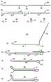
Fig. 1, at (a) to (K), show different views of different configurations and elements of an introducer according to one embodiment of the present disclosure;
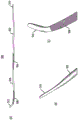
fig. 2 (a) and (B) show different views of different configurations and elements of an introducer according to another embodiment of the present disclosure;
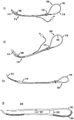
fig. 3 (a) to (F) show different views of different configurations and elements of an introducer according to yet another embodiment of the present disclosure;
fig. 4 (a) to (E) show different views of different configurations and elements of an introducer according to yet another embodiment of the present disclosure; and
fig. 5 (a) to (I) show different views of different configurations and elements of an introducer according to yet another embodiment of the present disclosure.
Detailed Description
In certain embodiments of the present disclosure, an improved introducer for endotracheal tube intubation works with direct laryngoscopes and video laryngoscopes. The design of the stylet is improved to have a rounded distal tip, eliminating the risk of tracheal injury. Nevertheless, the introducer is still sufficiently rigid to allow shaping of the covering sleeve for direct laryngoscopy or video laryngoscopy. Similar to a stylet, the introducer has a proximal end with a mechanism for quickly removing the stylet from the tracheal tube (after the tube has been placed in the trachea).
The improved introducer also functions effectively as a bougie, allowing for tracheal tactility, and allowing for the application of a tracheal tube over the rear end of the device and into the trachea. Unlike conventional rounded bougies, they also have inherent directionality, enabling the operator to always know the direction of the upturned distal tip (even when not visible-which is often the case with conventional bougies whenever the tip passes under the epiglottis).
Inserting a cannula into the trachea using a stylet (in order to create a shape up to the cuff and a narrow long axis) can be problematic if the rigidity of the stylet impedes insertion of the cannula. While a low bend angle (<35 degrees) reduces this risk, it does not eliminate it. As already mentioned, the shape of the tracheal tube tip may compress the tracheal ring, especially when a rigid stylet is placed into the end of the tube. This is particularly dangerous if the stylet protrudes beyond the cannula tip due to the rigidity and small diameter of the stylet. While bougies have a lower risk of catching tracheal rings, common disposable plastic bougies can be quite rigid down their long axis and can also cause tracheal trauma (perforation), or the tip can catch tracheal rings.
Similar to the stylet, the improved introducer allows for shaping with a cannula loaded thereon for visualization during placement ((i) low axis, about 35 degree bend for direct laryngoscopy or (ii) more exaggerated, about 70 degree bend for over-angle blade for use with Glidescope video laryngoscope), but at the same time, allows for "straight" insertion after the cannula tip has entered the trachea. Similar to bougies, the improved introducer is sufficiently rigid to maintain its narrow and long axis when inserted into the larynx, but is also not too rigid (so as to be "straight") when it passes the vocal cords and moves down the trachea.
The improved introducer allows for one-handed placement of the bougie and cannula. In addition to having the functional length and performance of the bougie when desired, the improved introducer also has a short storage length and an easily maneuverable stylet. Since the improved introducer functions equally well as a bougie or stylet, it allows for a reduction from two devices to only one required device. In many environments where an emergency airway is required, i.e. emergency services, tactical situations, ambulances, helicopters, etc., it is important to save space and reduce complexity (storage requirements). The improved introducer also allows for one-handed conversion of the device from being used as a stylet to being used as a bougie, which is advantageous when encountering unexpected insertion difficulties of the cannula.
Fig. 1 (a) to (K) illustrate an improved introducer 100 according to certain embodiments of the present disclosure. Fig. 1 (a) shows a side view of the introducer 100 in its fully open, straight configuration (e.g., for use as a bougie), while fig. 1 (B) shows a top plan view of portions of different segments of the introducer 100. As shown in fig. 1 (a) and (B), the introducer 100 has a hinge 102 for connecting a proximal "stylet" section 104 to a distal "bougie" section 106. In one embodiment, the proximal stylet section 104 is made of a malleable metal rod, the hinge 102 is made of a malleable plastic, and the distal stylet section 106 has mechanical properties, a tip 108, and a curved shape of a standard plastic stylet. The tip 108 is rounded, similar in shape to the bougie tip used to interact with the tracheal rings. The hinge segments allow the introducer to bend onto itself. As described below, the proximal stylet section 104 is relatively thin and can fit within a recess 110 in the upper half of the wider distal stylet section 106.
Fig. 1 (C) to (F) show transverse cross-sectional views of different segments of the introducer 100, wherein the proximal stylet segment 104 and the hinge 102 each have a generally rectangular transverse cross-section, with the hinge being defined by the larger of the two rectangles. The distal stylet segment 106 and the tip 108 have substantially circular transverse cross-sections of substantially equal diameter, except that the distal stylet segment 106 has a longitudinal groove 110 sized and shaped to receive the proximal stylet segment 104, e.g., friction fit, when the introducer 100 is folded over itself at the hinge 102 (e.g., as shown in fig. 1 (I) through (K)). In an alternative design, the longitudinal groove 110 is omitted and/or the proximal stylet section is cylindrical, similar to the round wire used for standard steel stylets. The wire for the proximal section 104 should be stiff enough to maintain the shape of the covering cannula, and small enough to fit along the distal probe-segment 106 with an outside diameter of no more than-5 mm (so that it will slide easily within an adult tracheal cannula with an inside diameter of 6.5-8.5 mm).
There are a number of ways in which the hinge segment 102 may be constructed. In the embodiment shown in fig. 1 (a), (B) and (D), the rectangular cross-section of the hinge allows the hinge to bend up and down, but with inherent opposite side-to-side strength. The hinge segments may be modified with ridges or other modifications to facilitate the desired bending, yet allow for the formation of loops for removal of the introducer when used as a stylet. The hinge 102 should be strong enough to keep the proximal stylet section 104 and the distal stylet section 106 moving within the same plane (bending up and down, rather than side-to-side). Straightening should also be allowed so that when the introducer is used as a bougie, the sleeve can slide along the proximal end, sliding over the hinge and into the trachea.
Fig. 1 (G) shows introducer 100 configured for use as a bougie, with hinge 102 bent to form an angle of about 100 degrees between proximal stylet segment 104 and distal bougie segment 106. Due to the straight shape of the hinge segment 102, the proximal stylet segment 104 can be configured to be substantially perpendicular to and approximately coplanar with the upturned tip 108 of the distal stylet segment 106. When the introducer 100 is used as a bougie for intubation, the operator is made aware of the orientation of the distal tip 108 because of the directionality provided to the introducer by the geometric relationship established between the bougie tip and the proximal segment by the hinge 102. Just like a bougie, after the introducer is placed within the trachea, a tracheal tube may be advanced over the rear end of the introducer and deployed into the trachea.
Fig. 1 (H) shows the introducer 100 pre-loaded with a tracheal tube 112, with the proximal stylet section 104 folded over the proximal end of the tube to prevent the tube from sliding off the proximal end of the introducer, and to form a handle 114 that provides directionality to the introducer 100. Unlike standard bougies, in this configuration, the introducer 100 may be pre-loaded with a tracheal tube and used with a one-handed technique. When the introducer and cannula are held together, the devices do not slide over each other.
Fig. 1 (I) shows an introducer 100 configured for efficient storage or configured for stylet use, wherein a proximal stylet segment 104 is folded over a distal stylet segment 106, where a curved hinge 102 forms a handle 116 that provides directionality to the introducer 100. With the introducer folded over itself, it is rigid to shape the tracheal tube and can be bent into the shape required for direct laryngoscopy or video laryngoscopy. It is noted that when the introducer 100 is folded into this configuration for stylet use, the bougie tip 108 extends beyond the proximal stylet section 104. This prevents the rigid stylet section from damaging the trachea if the tip of the introducer extends beyond the length of the cannula. Although not depicted in fig. 1 (I), the introducer 100 may be configured such that the proximal stylet segment 104 fits at least partially within the groove 110 of the distal stylet segment 106 (if not fully within the groove) to provide the introducer with a very small profile.
Fig. 1 (J) and (K) show an introducer 100 constructed as in fig. 1 (I) and pre-loaded with an endotracheal tube 112 for use as a stylet for direct laryngoscopy and video laryngoscopy, respectively, with the distal ends 118 of the sections 104 and 106 folded together bent approximately 35 degrees for direct laryngoscopy ((J) of fig. 1) and approximately 70 degrees for video laryngoscopy ((K) of fig. 1). In these configurations, the handle 116 formed by the hinge 102 acts as a grasping loop for removing the introducer after the cannula tip has been placed into the trachea.
The introducer 100 may have a lubricious coating to allow removal of the introducer through the tracheal tube when used as a bougie or when folded over itself and used as a stylet.
Fig. 2 (a) to (B) show an improved introducer 200 according to certain other embodiments of the present disclosure. Fig. 2 (a) shows a side view of an introducer 200 that is configured to function as a stylet or as a bougie depending on whether a tracheal tube (not shown) is preloaded onto the introducer. Introducer 200 has a malleable proximal section 202 connected to a distal body 204 by an attachment mechanism 206. In the configuration shown in fig. 2 (a), the proximal section 202 has been bent approximately 90 degrees at three different locations to form a handle 208, with the rear end 210 of the proximal section 202 engaging the attachment mechanism 206 to secure the proximal section in place and maintain its formed handle shape.
Fig. 2 (B) shows a close-up side view of handle 208 of fig. 2 (a) formed by curved proximal section 202 and attachment mechanism 206.
In this embodiment, introducer 200 is a rod between 50 and 65cm in length. This length enables introducer 200 to be used as a bougie when proximal segment 202 is not engaged with attachment mechanism 206, with introducer tip 212 inserted into the trachea (approximately 16 centimeters from the teeth to the laryngeal inlet), and then about 30 to 34cm of tracheal tube (not shown) inserted (i.e., placed down) into the rear end 210 of the introducer and into the trachea. It is noted that attachment mechanism 206 is designed such that after insertion of bougie tip 212 of the introducer, configured as shown in fig. 2 (a), into the trachea, the operator can disengage the attachment mechanism (e.g., with the same hand holding the introducer) to allow deployment of proximal segment 202 and deploy the tracheal tube down the rear end 210 of the introducer and into the trachea (e.g., with the operator's free hand).
The distal tip 212 of the introducer 200 is tipped up at an angle of approximately 35 degrees (between 30 and 40 degrees) to resemble the tip of a conventional bougie in shape and mechanical flexibility. The upturned tip 212 is preferably no more than 30 millimeters in length and the combined length of the upturned tip 212 and the body 204 is no more than about 25 millimeters. The average anterior-posterior size of female trachea is 14-16mm, and the average anterior-posterior size of male trachea is 15-20 mm. If the total length of the upturned tip and body is too great, introducer 200 may not be able to be inserted into the trachea without catching on the anterior tracheal ring.
In some embodiments, the curvature of introducer 200 has directionality, caused by the presence of a straight, malleable wire (not shown) embedded in the rod, starting at a point behind upturned distal tip 212 and extending proximally about 30 centimeters towards rear end 210. A flat, malleable wire (metal or plastic that can maintain its shape) provides rigidity for holding the tracheal tube in a predetermined shape. Tracheal tubes have an inherent arcuate shape and standard bougies cannot hold these tubes in a straightened position. Instead, it is the stylet that does-allowing the cannula body to straighten (and tip up the distal end). The straightness of the ductile wire means that the introducer will tend to bend such that it maintains its front-to-back orientation, i.e. the bend will preferably be up/down, as opposed to the bend that would occur with a round wire embedded within a round rod. One embodiment employs an oval-shaped bar along its entire length (with its side-to-side dimension being wider than its top-to-bottom dimension). This shape will cause preferential bending along the entire rod as well as along the embedded wire segments.
The shape of the elliptical rod has additional advantages. When sliding the tracheal tube down such an oval rod, the clearance at the sides of the rod (between the outer diameter of the rod and the inner diameter of the covering tracheal tube) will be smaller than the clearance between the top and bottom of the rod and the covering tube. This lateral gap is significant because if there is too much variance, the cannula may catch the laryngeal inlet when it is applied to the introducer. Almost all tracheal tubes use a tip-asymmetric left-facing bevel design, with the primary bevel facing-90 degrees from vertical when viewing the tube along its long axis, and the murphy eye (elliptical aperture in the body of the tube within one inch of the distal tip) located at the opposite right (+90 degrees) position. Thus, the front edge of the left-facing beveled sleeve is at +90 degrees. Standard cannulas have a left-facing bevel, either with a straight cut or with a slightly rounded tip. Parker cannulae (Parker tube) have a symmetrical slider-shaped tip. Turning the tracheal tube to the right when it contacts the tracheal ring causes the bevel to face upward and the slope to decrease, facilitating insertion. When there is a gap between the bougie (typically sized to an outer diameter of 5mm) and the covering sleeve (any size of 7.0-9.0 mm inner diameter in an adult), the gap strikes the right arytenoid and aryepiglottic folds. The side-to-side dimensions of the elliptical rod for introducer 200 may be slightly larger than a standard bougie, and conversely, the top-to-bottom dimensions are smaller than a standard bougie, which will minimize lateral clearance, but still have a similar degree or less surface contact between the devices (which will inhibit the sleeve from sliding over the bougie).
Located between about 30cm and about 50cm from the distal tip 212, the attachment mechanism 206 allows the curved proximal section 202 to lock in a fixed position approximately perpendicular to the body 204, as shown in fig. 2 (a). This bending of proximal section 202 on main body 204 creates a T-shape (i.e., between main body 204 and straight rear end 210 of proximal section 202), wherein rear end 210 (below the axis of main body 204) extends a distance preferably not more than 50 millimeters. The resulting handle 208 is aligned with (i.e., substantially coplanar with) the orientation of the distal upturned tip 212 of the introducer. The relative orientation results from a flat wire, the manner in which the attachment mechanism 206 engages the rear end 210, and/or the oval shape of the rod.
Fig. 2 (B) shows an attachment mechanism 206 corresponding to one possible design for engaging the rear end 210 of the curved proximal section 202. Many other designs are possible. These designs include, but are not limited to, a pin or hook connection, a locking snap mechanism, or a small magnetic clip. Some possible designs enable attachment (e.g., intersection of segments) at any number of points from the back end 210 of the ductile wire to about 5 centimeters from the attachment mechanism 206 along the proximal segment 202. This will allow the introducer to bend (and lock) itself to have a large or short handle, allowing the operator to change the functional length of the introducer.
The introducer 200 may be configured to function as a standard bougie, e.g., fully extended (straight), so that the cannula may be deployed over its entire length and into the trachea.
By bending proximal segment 202 and securing the proximal segment using attachment mechanism 206, the effective length of the introducer is shortened, which makes handling and insertion into the trachea easier. The resulting handle 208 provides an ergonomically efficient way to control the introducer and also gives the operator an indication of the orientation of the upturned tip 212. Once the tip 212 has been inserted into the trachea, the attachment mechanism 206 can be easily released, for example, by the operator holding the introducer with one hand at the T-shaped intersection. This allows the tracheal tube to be subsequently applied to the device (the released introducer now having no impediment to sliding the tracheal tube along the length of the introducer) and into the trachea. Accordingly, the attachment mechanism 206 (or other attachment points (not shown) on the body 204) should have a sufficiently small profile and/or shape so as not to restrict the tracheal tube from sliding down the introducer.
Alternatively, introducer 200 may be used as a stylet (shaped for direct laryngoscopy or video laryngoscopy), wherein the endotracheal tube is pre-loaded on the distal end of pre-configured introducer 200, as shown in fig. 2 (a), with distal tip 212 protruding beyond the pre-loaded cannula, and wherein engagement of curved proximal segment 202 with attachment mechanism 206 forms a stop that prevents further sliding of the endotracheal tube towards the proximal end of the introducer.
Fig. 3 (a) to (F) show an improved introducer 300 according to certain other embodiments of the present disclosure. Introducer 300 is similar to introducer 200 of fig. 2, except that attachment mechanism 306 for introducer 300 is different from attachment mechanism 206 of introducer 200. In particular, attachment mechanism 306 is a metal clip that wraps around the crossing segments of introducer 300 to hold them in place. It is noted that attachment mechanism 206 of fig. 2 is located at a fixed position along introducer 200, while attachment mechanism 306 of fig. 3 is movable so that it can be repositioned to a different position along introducer 300.
Fig. 3 (a) shows a side view of introducer 300 configured for use as a bougie having a relatively small handle 308, while fig. 3 (B) shows a side view of introducer 300 configured for use as a bougie having a relatively large handle 308. It is noted that by positioning attachment mechanism 306 at two different locations along introducer 300, two different handle sizes are achieved.
Fig. 3 (C) shows a side view of the introducer 300 configured for use as a stylet with a preloaded tracheal tube 304 for direct laryngoscopy (i.e., approximately 35 degree bend at its distal end), while fig. 3 (D) shows a side view of the introducer 300 configured for use as a stylet with a preloaded tracheal tube 304 for video laryngoscopy (i.e., approximately 70 degree bend at its distal end). Note that in fig. 3 (C) and (D), the location of attachment mechanism 306 in both configurations results in the distal end of the tracheal tube extending beyond distal tip 312 of introducer 300.
Fig. 3 (E) and (F) show side views of introducer 300 configured for use as a stylet with preloaded tracheal tube 304 for direct laryngoscopy and video laryngoscopy, respectively. It is noted that the location of the attachment mechanism 306 in both configurations results in the distal tip 312 of the introducer extending beyond the distal end of the tracheal tube, and the handle 308 in fig. 3 (E) and (F) is also smaller than the handle 308 in fig. 3 (C) and (D). In all four configurations of fig. 3 (C) to (F), the position of the attachment mechanism 306 determines the position of a stop that prevents further insertion of the tracheal tube 304 onto the introducer 300.
Fig. 4 (a) to (E) show an improved introducer 400 according to certain other embodiments of the present disclosure. Introducer 400 is similar to introducer 100 of fig. 1, except that attachment mechanism 406 for introducer 400 is different from attachment mechanism 206 of introducer 200. In particular, attachment mechanism 406 is comprised of a fixed male component 402 and two fixed female components 404(1) -404(2) located at two different positions along introducer 400. In general, the introducer may have one or more male components and one or more female components.
Fig. 4 (a) shows a side view of the introducer 400, and fig. 4 (B) shows a top plan view of the introducer 400. Note that the male component 402 is not visible in fig. 4 (a) because the male and female components are on opposite sides of the introducer.
Fig. 4 (C) and (D) show close-up top views of the male part 402 and the female part 404(i), respectively. The male component 402 includes a cylindrical or linear central post 408 covered by a cylindrical or linear cap 410 having a width greater than the width of the central post 408. Female component 404(i) includes two cylindrical or linear posts 412 separated by a distance that is greater than the width of central post 408, but less than the width of cap 410. To engage the attachment mechanism 406, the proximal section 414 of the introducer 400 is bent a total of about 270 degrees such that the central post 408 of the male component 402 is located between the two posts 412 of the female component 404(i), with the cap 410 of the male component 402 preventing the attachment mechanism 406 from disengaging and the introducer 400 from deploying.
Fig. 4 (E) shows the introducer 400 configured with a male component 402 engaged with a female component 404(i) to form a handle 416. It is noted that the positions of the two female parts 404(1) and 404(2) along the introducer 400 may be selected such that (i) configuring the introducer 400 with the male part 402 engaged with the female part 404(1) will result in a relatively large handle 416 for a stylet, for which case the distal end of a preloaded tracheal tube (not shown) will extend beyond the distal tip of the introducer, and (ii) alternatively configuring the introducer 400 with the male part 402 engaged with the female part 404(2) will result in a relatively small handle 416 for a stylet, for which case the distal tip of the introducer will extend beyond the distal end of a preloaded tracheal tube (not shown) of the same size. Here, also after the bougie tip 418 is inserted into the trachea, the operator may disengage the attachment mechanism 406 (e.g., with one hand) to enable the tracheal tube to be applied over the rear end of the introducer and into the trachea (e.g., with the operator's free hand).
Fig. 5 (a) to (I) show an improved introducer 500 according to certain other embodiments of the present disclosure. Fig. 5 (a) shows a side view of introducer 500. As shown in fig. 5 (a), the introducer 500 has a relatively flexible proximal section 502 connected to a first (proximal) malleable section 504 connected to a relatively flexible distal section 506 connected to a second (distal) malleable section 508. As shown in fig. 5 (B), the proximal end of the proximal section 502 has a straight (or otherwise reduced sized) tip 510, while the distal end of the second malleable section 508 has a conventional bougie tip 512 as shown in fig. 5 (C).
As used herein, the term "flexible" means that the segment can bend relatively easily, but does not necessarily maintain a bent shape on its own, and may require the application of some external maintenance force to hold the segment in its bent shape. On the other hand, the term "malleable" means that the segment can bend and will maintain the bent shape on itself without having to apply any external maintenance force.
In one embodiment, introducer 500 has an overall length of between about 50cm to about 70 cm. This length serves as a bougie when the introducer tip 512 has been inserted into the trachea and an approximately 30 to 34cm tracheal tube is subsequently inserted (i.e., discharged downwardly) over the rear end of the introducer and into the trachea.
The introducer 500 has directionality resulting from the presence of two malleable segments 504 and 508. The second malleable section 508 begins at a point behind the upturned distal tip 512 and extends proximally approximately 15 centimeters. The first malleable section 504 is located between about 25 to about 45 centimeters from the distal tip 512. The ductile section may be made of a tubular metallic material (including a hollow thin metal rod that slides over the bougie, a foil strip wrapped around the bougie, or a metallic material embedded in the rod, i.e., a wire or a straight wire).
The tracheal tube has an inherent arcuate shape and standard bougies cannot hold the tracheal tube in a straightened position. Instead, it is the stylet that does-allowing for straightening of the cannula body (and raising the distal tip). The two malleable segments 504 and 508 enable the introducer 500 to maintain a bendable shape at two points. This allows a variety of shaping options with or without a covering tracheal tube.
By having two malleable sections 504 and 508 that are more rigid than the intermediate distal section 506, there is preferential movement and flexibility between the malleable sections. For example, when a tracheal tube is slid over introducer 500 configured to act as a stylet, the malleable segments 504 and 508 may be shaped to have a shape that remains for insertion of the tube, but upon further insertion into the trachea, the distal segment 506 between the two malleable segments allows the introducer 500 to straighten.
Fig. 5 (D) shows introducer 500 configured to function as a bougie, with first malleable section 504 bent approximately 90 degrees to form a gripping region 514 for an operator, with proximal section 502 substantially coplanar with bougie tip 512. After the bougie tip 512 is inserted into the trachea, the operator can straighten the curved malleable section 504 (e.g., with one hand) and apply the tracheal tube over the rear end of the introducer and into the trachea (e.g., with the operator's free hand).
Fig. 5 (E) shows introducer 500 having the configuration of fig. 5 (D), but preloaded with tracheal tube 516. With the tracheal tube 516 inserted up to the 90 degree bend, the operator can hold both the proximal end of the tube and the introducer at the bend with one hand for effective insertion of the cannula of the stylet into the trachea.
Fig. 5 (F) shows a side view of the introducer 500 with the preloaded endotracheal tube 516 configured to serve as a stylet for direct laryngoscopy (i.e., having a bend of about 35 degrees at its second malleable segment 508), while fig. 5 (G) shows a side view of the introducer 500 with the preloaded endotracheal tube 516 configured to serve as a stylet for video laryngoscopy (i.e., having a bend of about 70 degrees at its second malleable segment 508). In these configurations, the handle 518 is formed by bending the flexible proximal section 502 a total of about 180 degrees and forcing the straight proximal tip 510 into the proximal end of the over tracheal tube 516 to secure everything in place. It is noted that the length of introducer 500 inserted within cannula 516 determines (i) whether the distal end of cannula 516 extends beyond distal tip 512 of introducer 500, or vice versa, and (ii) the size of handle 518. Fig. 5 (H) shows a side view of introducer 500 configured for use as a stylet, where (i) distal tip 512 of introducer 500 extends beyond the distal end of cannula 516, and (ii) handle 518 is smaller than the handles of fig. 5 (F) and (G).
The straight proximal tip 510 gives the introducer 500 inherent directionality (i.e., the operator knows the orientation of the distal introducer tip 512 by the orientation of the straight proximal tip 510). By crimping the proximal section 502 upon itself (and securing the proximal section by a tracheal tube connector), the length of the introducer is reduced, which makes it easier to handle and insert into the trachea. The proximal crimp provides an ergonomically effective way to control the introducer and also gives the operator an indication of the orientation of the upturned bougie tip 512.
Fig. 5 (I) shows a side view of an introducer 500 configured for effective packaging or storage, wherein the flexible proximal end segment 502 and the first malleable segment 504 provide a total bend angle of about 180 degrees. It is noted that a band 520 or other fastener 522 may be employed to secure the introducer 500 in this configuration.
The standard method of dealing with over-angled stylets is to retract the stylet after the cannula tip has passed through a thin cable (cord), and then attempt to push the cannula down into the trachea. However, the cannula, upon exiting the upwardly directed stylet, will follow the upward curvature of the stylet, rather than following the downward slope of the trachea. This may result in mechanical compression. In another method, both the stylet and cannula are rotated 90 degrees to the right. The cannula can then be pushed off the stylet with one hand (i.e., can be done without assistance). In another approach, the cannula is rotated 90 degrees to the right alone (e.g., with the assistance of another person). Both of these methods solve the problems of wrinkling (bevel up) and canting (sleeve down).
Unless otherwise expressly stated, each numerical value and range should be construed as being approximate as if the word "about" or "approximately" preceded the value or range.
It will be further understood that various changes in the details, materials, and arrangements of the parts which have been described and illustrated in order to explain the embodiments of this invention may be made by those skilled in the art without departing from the embodiments of the invention encompassed by the following claims.
In this specification, including any claims, the term "each" may be used to refer to one or more specified characteristics of a plurality of previously listed elements or steps. When used with the open-ended term "comprising," reference to the term "each" does not exclude additional, unrecited elements or steps. Thus, it will be understood that an apparatus may have additional non-enumerated elements, and a method may have additional non-enumerated steps, where the additional non-enumerated elements or steps do not have one or more specified characteristics.
The use of reference numerals and/or signs in the claims is intended to identify one or more possible embodiments of the claimed subject matter in order to facilitate the interpretation of the claims. Such use should not necessarily limit the scope of those claims to the embodiments shown in the corresponding figures.
Reference herein to "one embodiment" or "an embodiment" means that a particular feature, structure, or characteristic described in connection with the embodiment can be included in at least one embodiment of the invention. The appearances of the phrase "in one embodiment" in various places in the specification are not necessarily all referring to the same embodiment, nor are separate or alternative embodiments necessarily mutually exclusive of other embodiments. The same applies to the term "embodiment".
Claims (19)
1. An introducer for endotracheal tube intubation, the introducer comprising a proximal section connected to a distal section having an angled bougie tip, wherein:
the introducer can be configured to act as a bougie, wherein a tracheal tube is deployed over a rear end of the introducer and into a trachea; and is
The introducer can be configured to act as a stylet, with a tracheal tube preloaded thereon for insertion into the trachea.
2. The introducer of claim 1, wherein the proximal segment is flexible or malleable.
3. The introducer of claim 2, wherein the proximal segment is designed to be directionally curved to be substantially coplanar with the angled bougie tip.
4. The introducer of claim 3, wherein there is at least one of:
the proximal section width is greater than its thickness to facilitate the directional bending; and
the proximal section includes a straight inner wire that facilitates the directional bend.
5. The introducer of claim 2, wherein:
the proximal section is bendable to form a handle; and is
The introducer also includes an attachment mechanism that holds the handle when the attachment mechanism is engaged.
6. The introducer of claim 5, wherein the attachment mechanism is disengagable to allow the proximal segment to straighten, such that an operator can (i) begin using the introducer as the bougie, configure the introducer with the handle, and then (ii) disengage the attachment mechanism to allow the tracheal tube to be applied over the rear end of the introducer and into the trachea.
7. The introducer of claim 5, wherein the attachment mechanism enables the introducer to be configured differently with handles of different sizes.
8. The introducer of claim 5, wherein the attachment mechanism forms a stop that prevents further insertion of a preloaded tracheal tube onto the introducer configured to serve as the stylet.
9. The introducer of claim 8, wherein the attachment mechanism is engageable at different locations along the introducer such that:
in a first position, the bougie tip extends beyond the distal end of the entire preloaded tracheal tube; and
in the second position, the distal end of the entire preloaded tracheal tube extends beyond the bougie tip.
10. The introducer of claim 2 wherein a proximal end of the proximal segment has a reduced size compared to the remainder of the proximal segment such that when the introducer is configured to function as the stylet, the proximal segment can be bent approximately 180 degrees and the reduced proximal end can be inserted into the rear end of the preloaded tracheal tube to form and maintain a handle for the introducer.
11. The introducer of claim 10, wherein a proximal end of the proximal segment is straight compared to the rest of the proximal segment.
12. The introducer of claim 1, wherein the distal section is malleable such that it can be bent at different angles for direct or video laryngoscopy, wherein the malleable distal section is designed to bend directionally such that it bends substantially coplanar with the angled bougie tip.
13. The introducer of claim 1, wherein:
the proximal section comprises:
a first flexible subsection (e.g., 502) at a rear end of the introducer; and
a first malleable sub-segment (e.g., 504) connected to the first flexible sub-segment;
and the distal section comprises:
a second flexible subsegment (e.g., 506) connected to the first malleable subsegment of the proximal segment; and
a second malleable segment (e.g., 508) connected to the second flexible segment and having the angled bougie tip.
14. The introducer of claim 13, wherein:
the proximal section is capable of bending less than 180 degrees to form a gripping area;
the gripping region forming a stop that prevents further insertion of the preloaded tracheal tube onto the introducer configured to serve as the stylet; and is
The proximal segment is bendable at different locations along the introducer such that:
in a first position, the bougie tip extends beyond the distal end of the entire preloaded tracheal tube; and
in the second position, the distal end of the entire preloaded tracheal tube extends beyond the bougie tip.
15. The introducer of claim 13, wherein the proximal segment is designed to bend directionally such that the bent proximal segment is substantially coplanar with the angled bougie tip, wherein there is at least one of:
the proximal section having a width greater than its thickness to facilitate the directional bending; and
the proximal section includes a straight inner wire that facilitates the directional bend.
16. The introducer of claim 13 wherein a proximal end of the proximal segment has a reduced size compared to the remainder of the proximal segment such that when the introducer is configured to function as the stylet, the proximal segment can be bent approximately 180 degrees and the reduced proximal end can be inserted into the rear end of the preloaded tracheal tube to form and maintain a handle for the introducer.
17. The introducer of claim 16, wherein a proximal end of the proximal segment is straight compared to the rest of the proximal segment.
18. The introducer of claim 13, wherein the distal section is malleable such that it can be bent at different angles for direct or video laryngoscopy, wherein the malleable distal section is designed to bend directionally such that it bends substantially coplanar with the angled bougie tip.
19. The introducer of claim 18, wherein:
the proximal section is capable of bending less than 180 degrees to form a grip region that forms a stop that prevents further insertion of the preloaded tracheal tube onto the introducer configured to serve as the stylet;
the proximal segment is bendable at different locations along the introducer such that:
in a first position, the bougie tip extends beyond the distal end of the entire preloaded tracheal tube; and
in a second position, the distal end of the entire preloaded tracheal tube extends beyond the bougie tip;
the proximal section is designed to bend directionally such that the bent proximal section is substantially coplanar with the angled bougie tip, wherein there is at least one of:
the proximal section width is greater than its thickness to facilitate the directional bending; and
the proximal section comprises a straight inner wire that facilitates the directional bend;
a proximal end of the proximal segment is flat compared to the rest of the proximal segment such that when the introducer is configured to function as the stylet, the proximal segment can be bent approximately 180 degrees and the flat proximal end can be inserted into the rear end of the preloaded tracheal tube to form and maintain a handle for the introducer; and
the distal section is malleable such that it can be bent at different angles for direct or video laryngoscopy, wherein the malleable distal section is designed to bend directionally such that it bends substantially coplanar with the angled bougie tip.
Applications Claiming Priority (5)
| Application Number | Priority Date | Filing Date | Title |
|---|---|---|---|
| US201462051464P | 2014-09-17 | 2014-09-17 | |
| US62/051,464 | 2014-09-17 | ||
| US201462054487P | 2014-09-24 | 2014-09-24 | |
| US62/054,487 | 2014-09-24 | ||
| CN201580062191.7A CN106999031B (en) | 2014-09-17 | 2015-09-16 | Introducer for tracheal cannula |
Related Parent Applications (1)
| Application Number | Title | Priority Date | Filing Date |
|---|---|---|---|
| CN201580062191.7A Division CN106999031B (en) | 2014-09-17 | 2015-09-16 | Introducer for tracheal cannula |
Publications (1)
| Publication Number | Publication Date |
|---|---|
| CN111700579A true CN111700579A (en) | 2020-09-25 |
Family
ID=54207783
Family Applications (2)
| Application Number | Title | Priority Date | Filing Date |
|---|---|---|---|
| CN202010514550.0A Pending CN111700579A (en) | 2014-09-17 | 2015-09-16 | Introducer for tracheal cannula |
| CN201580062191.7A Active CN106999031B (en) | 2014-09-17 | 2015-09-16 | Introducer for tracheal cannula |
Family Applications After (1)
| Application Number | Title | Priority Date | Filing Date |
|---|---|---|---|
| CN201580062191.7A Active CN106999031B (en) | 2014-09-17 | 2015-09-16 | Introducer for tracheal cannula |
Country Status (9)
| Country | Link |
|---|---|
| US (2) | US10569039B2 (en) |
| EP (2) | EP3811848B1 (en) |
| JP (2) | JP6633638B2 (en) |
| CN (2) | CN111700579A (en) |
| AU (2) | AU2015317815B2 (en) |
| ES (1) | ES2848321T3 (en) |
| PL (1) | PL3193696T3 (en) |
| PT (1) | PT3193696T (en) |
| WO (1) | WO2016044438A1 (en) |
Families Citing this family (10)
| Publication number | Priority date | Publication date | Assignee | Title |
|---|---|---|---|---|
| US10569039B2 (en) * | 2014-09-17 | 2020-02-25 | Richard M. Levitan | Introducer for tracheal tube intubation |
| US10272217B2 (en) * | 2015-12-08 | 2019-04-30 | Boyi Gao | Device for gripping and directing bougies for intubation |
| GB2547017B (en) * | 2016-02-04 | 2021-08-04 | Intersurgical Ag | Improvements to intubation aids |
| WO2018064185A1 (en) | 2016-09-27 | 2018-04-05 | Maslow Andrew | Intubating endoscopic device |
| US20190217034A1 (en) * | 2016-09-27 | 2019-07-18 | Andrew Maslow | Intubating endoscopic device |
| JP6758670B2 (en) | 2017-01-23 | 2020-09-23 | 学校法人帝京大学 | Tracheal tube insertion aid kit |
| FR3093634B1 (en) | 2019-03-11 | 2021-02-19 | Stepagil | Intubation candle |
| US11724053B2 (en) | 2020-04-01 | 2023-08-15 | Boyi Gao | Device for gripping and securing an intubation bougie |
| US20220184334A1 (en) * | 2020-12-16 | 2022-06-16 | Tien-Sheng Chen | Endotracheal Tube |
| CN113648500A (en) * | 2021-08-15 | 2021-11-16 | 江苏威茂医疗科技有限公司 | Guiding type trachea cannula |
Citations (5)
| Publication number | Priority date | Publication date | Assignee | Title |
|---|---|---|---|---|
| US3957055A (en) * | 1974-09-23 | 1976-05-18 | Linder Gerald S | Catheter guide |
| US4185639A (en) * | 1978-03-27 | 1980-01-29 | Linder Gerald S | Adjustable stop for endotracheal tube guide |
| US5095888A (en) * | 1990-07-09 | 1992-03-17 | Circon Corporation | Intubating stylet for a laryngoscope |
| US20080017195A1 (en) * | 2006-07-19 | 2008-01-24 | Yoshida Douglas K | Extendable lighted intubation stylet |
| US20100108060A1 (en) * | 2006-06-01 | 2010-05-06 | Truphatek International Ltd | Hand operated articulated intubation stylet |
Family Cites Families (47)
| Publication number | Priority date | Publication date | Assignee | Title |
|---|---|---|---|---|
| US4448741A (en) | 1981-12-07 | 1984-05-15 | Husky Injection Molding Systems Ltd. | Method of molding plastic workpieces about slender permanent inserts |
| JPS6170889A (en) | 1984-09-14 | 1986-04-11 | Toshiba Corp | Automatic gain control circuit in magnetic recording and reproducing device |
| JPH01174426A (en) | 1987-12-28 | 1989-07-11 | Meiji Rubber Kasei:Kk | Method for fitting insert member in injection molding die |
| US5177261A (en) | 1991-07-22 | 1993-01-05 | Mallinckrodt Medical, Inc. | Synthesis of ioversol using chloroacetyl chloride |
| DE4140101C1 (en) | 1991-12-05 | 1993-07-08 | Sueddeutsche Feinmechanik Gmbh, 6480 Waechtersbach, De | |
| US5259377A (en) | 1992-03-30 | 1993-11-09 | Stephen M. Daugherty | Endotracheal tube stylet |
| DE4229152A1 (en) | 1992-09-01 | 1994-03-03 | Jordan As Oslo | Toothbrush and manufacturing process for toothbrushes |
| JPH0784022B2 (en) | 1992-12-04 | 1995-09-13 | 株式会社アシックス | Racket frame manufacturing method |
| US5377689A (en) | 1993-12-27 | 1995-01-03 | Mercereau; Steven F. | Sampling syringe |
| BE1009384A3 (en) | 1995-05-10 | 1997-03-04 | Boucherie Nv G B | Method and apparatus for manufacturing brush bodies. |
| EP1054761B1 (en) | 1998-12-10 | 2004-02-25 | Trisa Holding AG | Plastic object for use in personal hygiene |
| US6579485B2 (en) | 2000-12-15 | 2003-06-17 | Haun Drop Forge Co. Ltd. | Method of injection molding around the surface of an object |
| DE10065517A1 (en) | 2000-12-28 | 2002-07-04 | Trisa Holding Ag Triengen | Method of making a toothbrush |
| US6630089B2 (en) | 2001-05-18 | 2003-10-07 | Chao-Yueh Chuang | Process for forming a molded plastic layer on a metal plate |
| TW592846B (en) | 2003-10-17 | 2004-06-21 | Jewelry Alvin Lee Inc | Method for making tubular object and product thereof |
| US7650886B1 (en) * | 2004-03-04 | 2010-01-26 | Christian Keller | Esophageal airway management device guides |
| US7955543B2 (en) | 2004-04-30 | 2011-06-07 | Medtronic, Inc. | Method of overmolding a substrate |
| US8109983B2 (en) | 2004-08-06 | 2012-02-07 | Boston Scientific Scimed, Inc. | Medical device delivery systems |
| US7234939B2 (en) | 2004-11-23 | 2007-06-26 | Ultradent Products, Inc. | Dental instruments having a handle formed by two-shot molding |
| GB0603010D0 (en) | 2006-02-15 | 2006-03-29 | Owen Greenings & Mumford Ltd | Bougie |
| FR2899981B1 (en) | 2006-04-18 | 2008-05-30 | Logo Sa | FILIFORM ELEMENT, IN PARTICULAR BRANCH OF EYEWEAR, AND METHOD OF OBTAINING IT. |
| US8695590B2 (en) * | 2006-06-12 | 2014-04-15 | Parker Medical, Inc. | Adjustable stylet for endotracheal tube |
| US20070290399A1 (en) | 2006-06-20 | 2007-12-20 | Bradshaw Medical, Inc. | Handle and method of making thereof |
| US8343408B2 (en) * | 2006-10-12 | 2013-01-01 | Smith Michael P | Method of molding an endotracheal tube for tracheal intubation |
| US20130211263A1 (en) * | 2007-03-23 | 2013-08-15 | The Board Of Regents Of The University Of Nebraska | Intubation guide |
| DE102007023129A1 (en) | 2007-05-16 | 2008-11-20 | Raumedic Ag | A process for the production of a plastic product with a plastic hard component and a plastic soft component as well as plastic product produced by the process |
| US7655543B2 (en) | 2007-12-21 | 2010-02-02 | Asm America, Inc. | Separate injection of reactive species in selective formation of films |
| US8435433B2 (en) | 2008-02-04 | 2013-05-07 | The Gillette Company | Method for making a handle for a personal grooming device |
| US20090240236A1 (en) | 2008-03-20 | 2009-09-24 | Composite Plastic, Inc. | Reinforced medical tubing |
| US8641955B2 (en) | 2008-08-08 | 2014-02-04 | Gauthier Biomedical Inc. | Method for forming a molded component for an item |
| US9913964B2 (en) * | 2008-12-29 | 2018-03-13 | Acclarnet, Inc. | System and method for dilating an airway stenosis |
| US8887717B2 (en) | 2009-10-15 | 2014-11-18 | Airway Cam Technologies, Inc. | Introducer for surgical airway catheters |
| EP2488115A1 (en) | 2009-10-15 | 2012-08-22 | Airway Cam Technologies, Inc. | Introducer for surgical airway catheters |
| US8336541B2 (en) | 2009-11-24 | 2012-12-25 | Ai Medical Devices, Inc. | Endotracheal intubation device |
| US20130035548A1 (en) | 2010-03-22 | 2013-02-07 | Tufts Medical Center, Inc. | Fiber optic intubating device |
| US8677990B2 (en) * | 2010-04-28 | 2014-03-25 | Syncro Medical Innovations, Inc. | Endo-tracheal intubation device with adjustably bendable stylet |
| US20130096482A1 (en) | 2011-10-18 | 2013-04-18 | Medtronic Xomed, Inc. | Alternate geometry stylet for ventricular shunt catheter placement |
| TWI537017B (en) * | 2012-03-13 | 2016-06-11 | Lin Que Hong | Intubation assist device |
| GB2500633A (en) | 2012-03-27 | 2013-10-02 | Louise Mohn | Moulding method |
| GB2507474A (en) * | 2012-09-18 | 2014-05-07 | P3 Medical Ltd | Medical device with hydrophilic coating |
| US10105886B2 (en) | 2012-10-09 | 2018-10-23 | Reliant Worldwide Plastics, Llc | Thermoplastic injection molded element with integral thermoplastic positioning system for reinforced composite structures |
| JP6072986B2 (en) | 2013-07-12 | 2017-02-01 | ボストン サイエンティフィック ニューロモデュレイション コーポレイション | Lead having segment electrode and method of manufacturing and using lead |
| CN105392523A (en) | 2013-07-22 | 2016-03-09 | 波士顿科学神经调制公司 | Methods of manufacturing molded segmented electrode leads |
| US20150042011A1 (en) | 2013-08-08 | 2015-02-12 | Supreme Technic Package Co., Ltd. | Positioning structure of the object to be coated and its manufa cturing method |
| US11547823B2 (en) | 2014-04-11 | 2023-01-10 | Nilesh R. Vasan | Bougie and method of making and using the same |
| US9427543B2 (en) * | 2014-05-05 | 2016-08-30 | Deye Wei | Intubation device and method |
| US10569039B2 (en) * | 2014-09-17 | 2020-02-25 | Richard M. Levitan | Introducer for tracheal tube intubation |
-
2015
- 2015-09-16 US US15/511,654 patent/US10569039B2/en active Active
- 2015-09-16 CN CN202010514550.0A patent/CN111700579A/en active Pending
- 2015-09-16 EP EP20209455.3A patent/EP3811848B1/en active Active
- 2015-09-16 JP JP2017534897A patent/JP6633638B2/en active Active
- 2015-09-16 PT PT157714072T patent/PT3193696T/en unknown
- 2015-09-16 ES ES15771407T patent/ES2848321T3/en active Active
- 2015-09-16 AU AU2015317815A patent/AU2015317815B2/en active Active
- 2015-09-16 CN CN201580062191.7A patent/CN106999031B/en active Active
- 2015-09-16 EP EP15771407.2A patent/EP3193696B1/en active Active
- 2015-09-16 PL PL15771407T patent/PL3193696T3/en unknown
- 2015-09-16 WO PCT/US2015/050452 patent/WO2016044438A1/en active Application Filing
-
2019
- 2019-12-12 JP JP2019224417A patent/JP6889236B2/en active Active
-
2020
- 2020-01-14 US US16/741,946 patent/US11690967B2/en active Active
- 2020-12-04 AU AU2020281147A patent/AU2020281147B2/en active Active
Patent Citations (5)
| Publication number | Priority date | Publication date | Assignee | Title |
|---|---|---|---|---|
| US3957055A (en) * | 1974-09-23 | 1976-05-18 | Linder Gerald S | Catheter guide |
| US4185639A (en) * | 1978-03-27 | 1980-01-29 | Linder Gerald S | Adjustable stop for endotracheal tube guide |
| US5095888A (en) * | 1990-07-09 | 1992-03-17 | Circon Corporation | Intubating stylet for a laryngoscope |
| US20100108060A1 (en) * | 2006-06-01 | 2010-05-06 | Truphatek International Ltd | Hand operated articulated intubation stylet |
| US20080017195A1 (en) * | 2006-07-19 | 2008-01-24 | Yoshida Douglas K | Extendable lighted intubation stylet |
Also Published As
| Publication number | Publication date |
|---|---|
| US20200164167A1 (en) | 2020-05-28 |
| JP6889236B2 (en) | 2021-06-18 |
| PL3193696T3 (en) | 2021-05-17 |
| EP3811848B1 (en) | 2024-03-27 |
| WO2016044438A1 (en) | 2016-03-24 |
| PT3193696T (en) | 2021-02-04 |
| AU2020281147A1 (en) | 2021-01-07 |
| US10569039B2 (en) | 2020-02-25 |
| JP6633638B2 (en) | 2020-01-22 |
| AU2015317815A1 (en) | 2017-05-11 |
| JP2020072930A (en) | 2020-05-14 |
| JP2017530844A (en) | 2017-10-19 |
| EP3193696B1 (en) | 2020-12-09 |
| US11690967B2 (en) | 2023-07-04 |
| ES2848321T3 (en) | 2021-08-06 |
| AU2020281147B2 (en) | 2022-02-17 |
| CN106999031A (en) | 2017-08-01 |
| US20170246410A1 (en) | 2017-08-31 |
| AU2015317815B2 (en) | 2020-10-22 |
| EP3811848A1 (en) | 2021-04-28 |
| CN106999031B (en) | 2020-07-03 |
| EP3193696A1 (en) | 2017-07-26 |
Similar Documents
| Publication | Publication Date | Title |
|---|---|---|
| CN106999031B (en) | Introducer for tracheal cannula | |
| KR102478836B1 (en) | System and method for facilitating an intubation | |
| EP3052171B1 (en) | Artificial airway device | |
| US9174014B2 (en) | Introducer guide | |
| US20090090357A1 (en) | Guide device for tracheal intubation | |
| US8887717B2 (en) | Introducer for surgical airway catheters | |
| US9579476B2 (en) | Device for introducing an airway tube into the trachea | |
| CN206586982U (en) | A kind of neuroprotection drag hook |
Legal Events
| Date | Code | Title | Description |
|---|---|---|---|
| PB01 | Publication | ||
| PB01 | Publication | ||
| SE01 | Entry into force of request for substantive examination | ||
| SE01 | Entry into force of request for substantive examination |