JP6072986B2 - Lead having segment electrode and method of manufacturing and using lead - Google Patents
Lead having segment electrode and method of manufacturing and using lead Download PDFInfo
- Publication number
- JP6072986B2 JP6072986B2 JP2016525405A JP2016525405A JP6072986B2 JP 6072986 B2 JP6072986 B2 JP 6072986B2 JP 2016525405 A JP2016525405 A JP 2016525405A JP 2016525405 A JP2016525405 A JP 2016525405A JP 6072986 B2 JP6072986 B2 JP 6072986B2
- Authority
- JP
- Japan
- Prior art keywords
- lead
- electrode
- stimulation
- along
- central hub
- Prior art date
- Legal status (The legal status is an assumption and is not a legal conclusion. Google has not performed a legal analysis and makes no representation as to the accuracy of the status listed.)
- Expired - Fee Related
Links
Images


Classifications
-
- A—HUMAN NECESSITIES
- A61—MEDICAL OR VETERINARY SCIENCE; HYGIENE
- A61N—ELECTROTHERAPY; MAGNETOTHERAPY; RADIATION THERAPY; ULTRASOUND THERAPY
- A61N1/00—Electrotherapy; Circuits therefor
- A61N1/02—Details
- A61N1/04—Electrodes
- A61N1/05—Electrodes for implantation or insertion into the body, e.g. heart electrode
- A61N1/0526—Head electrodes
- A61N1/0529—Electrodes for brain stimulation
- A61N1/0534—Electrodes for deep brain stimulation
-
- A—HUMAN NECESSITIES
- A61—MEDICAL OR VETERINARY SCIENCE; HYGIENE
- A61B—DIAGNOSIS; SURGERY; IDENTIFICATION
- A61B2562/00—Details of sensors; Constructional details of sensor housings or probes; Accessories for sensors
- A61B2562/12—Manufacturing methods specially adapted for producing sensors for in-vivo measurements
- A61B2562/125—Manufacturing methods specially adapted for producing sensors for in-vivo measurements characterised by the manufacture of electrodes
-
- A—HUMAN NECESSITIES
- A61—MEDICAL OR VETERINARY SCIENCE; HYGIENE
- A61B—DIAGNOSIS; SURGERY; IDENTIFICATION
- A61B5/00—Measuring for diagnostic purposes; Identification of persons
- A61B5/24—Detecting, measuring or recording bioelectric or biomagnetic signals of the body or parts thereof
-
- A—HUMAN NECESSITIES
- A61—MEDICAL OR VETERINARY SCIENCE; HYGIENE
- A61M—DEVICES FOR INTRODUCING MEDIA INTO, OR ONTO, THE BODY; DEVICES FOR TRANSDUCING BODY MEDIA OR FOR TAKING MEDIA FROM THE BODY; DEVICES FOR PRODUCING OR ENDING SLEEP OR STUPOR
- A61M25/00—Catheters; Hollow probes
- A61M25/0009—Making of catheters or other medical or surgical tubes
-
- A—HUMAN NECESSITIES
- A61—MEDICAL OR VETERINARY SCIENCE; HYGIENE
- A61M—DEVICES FOR INTRODUCING MEDIA INTO, OR ONTO, THE BODY; DEVICES FOR TRANSDUCING BODY MEDIA OR FOR TAKING MEDIA FROM THE BODY; DEVICES FOR PRODUCING OR ENDING SLEEP OR STUPOR
- A61M25/00—Catheters; Hollow probes
- A61M25/01—Introducing, guiding, advancing, emplacing or holding catheters
- A61M25/0102—Insertion or introduction using an inner stiffening member, e.g. stylet or push-rod
-
- A—HUMAN NECESSITIES
- A61—MEDICAL OR VETERINARY SCIENCE; HYGIENE
- A61N—ELECTROTHERAPY; MAGNETOTHERAPY; RADIATION THERAPY; ULTRASOUND THERAPY
- A61N1/00—Electrotherapy; Circuits therefor
- A61N1/02—Details
- A61N1/04—Electrodes
- A61N1/05—Electrodes for implantation or insertion into the body, e.g. heart electrode
- A61N1/0551—Spinal or peripheral nerve electrodes
-
- Y—GENERAL TAGGING OF NEW TECHNOLOGICAL DEVELOPMENTS; GENERAL TAGGING OF CROSS-SECTIONAL TECHNOLOGIES SPANNING OVER SEVERAL SECTIONS OF THE IPC; TECHNICAL SUBJECTS COVERED BY FORMER USPC CROSS-REFERENCE ART COLLECTIONS [XRACs] AND DIGESTS
- Y10—TECHNICAL SUBJECTS COVERED BY FORMER USPC
- Y10T—TECHNICAL SUBJECTS COVERED BY FORMER US CLASSIFICATION
- Y10T29/00—Metal working
- Y10T29/49—Method of mechanical manufacture
- Y10T29/49002—Electrical device making
- Y10T29/49117—Conductor or circuit manufacturing
- Y10T29/49174—Assembling terminal to elongated conductor
- Y10T29/49176—Assembling terminal to elongated conductor with molding of electrically insulating material
Description
〔関連出願との相互参照〕
本出願は、2013年7月12日に出願された米国仮特許出願第61/845,739号の合衆国法典第35編第119条(e)に基づく利益を主張するものであり、この米国仮特許出願を本明細書に援用する。
[Cross-reference with related applications]
This application claims the benefit of US Provisional Patent Application No. 61 / 845,739, filed July 12, 2013, from 35 USC 119 (e). Patent applications are incorporated herein by reference.
本発明は、電気刺激システム及びリード、並びにこれらのシステム及びリードの製造及び使用方法の分野に関する。本発明は、除去可能な中心ハブを含むセグメント電極を備えたリードを有する電気刺激システム、並びにこれらのセグメント電極、リード及び電気刺激システムの製造及び使用方法にも関する。 The present invention relates to the field of electrical stimulation systems and leads, and methods for making and using these systems and leads. The present invention also relates to electrical stimulation systems having leads with segment electrodes including a removable central hub, and methods of making and using these segment electrodes, leads and electrical stimulation systems.
電気刺激は、様々な病状の治療に有用である。脳深部刺激は、例えば、パーキンソン病、ジストニア、本態性振戦、慢性疼痛、ハンチントン病、レボドパ誘発性運動障害及び筋硬直、動作緩慢、てんかん及び発作、摂食障害、並びに気分障害の治療に有用となり得る。典型的には、先端又は先端近くに刺激電極を有するリードによって脳の標的ニューロンに刺激を与える。磁気共鳴画像(MRI)又はコンピュータ断層撮影(CT)スキャンは、標的ニューロンに所望の刺激を与えるために刺激電極をどこに配置すべきかを決定するための開始点を提供することができる。 Electrical stimulation is useful for the treatment of various medical conditions. Deep brain stimulation is useful, for example, in the treatment of Parkinson's disease, dystonia, essential tremor, chronic pain, Huntington's disease, levodopa-induced movement disorders and muscle rigidity, slow movement, epilepsy and seizures, eating disorders, and mood disorders Can be. Typically, the brain target neurons are stimulated by a lead having a stimulating electrode at or near the tip. Magnetic resonance imaging (MRI) or computed tomography (CT) scans can provide a starting point for determining where the stimulation electrodes should be placed to deliver the desired stimulation to the target neurons.
患者の脳内にリードを埋込んだ後、リード上の選択された電極を通じて電気刺激電流を送出し、脳の標的ニューロンを刺激する。通常、電極は、リードの遠位部に配置されたリングの形に構成される。刺激電流は、リング電極から全ての方向に等しく放出される。これらの電極のリング形状に起因して、リング電極の周囲の1又はそれ以上の特定の位置(例えば、リードの1又はそれ以上の側部又は点、周囲)に刺激電流を向けることはできない。この結果、方向性を失った刺激が隣接する神経組織に不要な刺激をもたらし、望ましくない副作用を生じさせることがある。 After the lead is implanted in the patient's brain, an electrical stimulation current is delivered through selected electrodes on the lead to stimulate target brain neurons. Typically, the electrode is configured in the form of a ring located at the distal portion of the lead. Stimulation current is emitted equally from the ring electrode in all directions. Due to the ring shape of these electrodes, the stimulation current cannot be directed to one or more specific locations around the ring electrode (eg, one or more sides or points of the lead, perimeter). As a result, stimuli that have lost directionality can cause unwanted stimuli in adjacent neural tissue, causing undesirable side effects.
1つの実施形態では、刺激リードの作成方法が、リード本体の遠位端部分に沿って少なくとも1つのプレ電極を配置するステップを含む。少なくとも1つのプレ電極は、近位端部及び遠位端部を有するプレ電極本体を含む。プレ電極本体は、導電性中心ハブと、中心ハブに個別に結合されて中心ハブから半径方向外向きに延びる導電性刺激部材とを含み、複数の刺激部材の各々は、中心ハブのみを介して残りの複数の刺激部材の各々に電気的に結合される。刺激部材の各々には、リード本体の近位端部分に沿って配置された端子から延びる複数の導体のうちの少なくとも1つの導体が電気的に結合される。中心ハブの長手方向面の周囲には非導電性材料が配置され、非導電性材料は、複数の刺激部材の内面に当接する。プレ電極本体から中心ハブを除去して刺激部材の各々を互いに電気的に絶縁することにより、刺激部材を、非導電性材料の外周に沿って配置された電気的に絶縁されたセグメント電極に変換する。 In one embodiment, a method for creating a stimulation lead includes positioning at least one pre-electrode along the distal end portion of the lead body. The at least one pre-electrode includes a pre-electrode body having a proximal end and a distal end. The pre-electrode body includes a conductive central hub and a conductive stimulation member individually coupled to the central hub and extending radially outward from the central hub, each of the plurality of stimulation members being routed via only the central hub. It is electrically coupled to each of the remaining plurality of stimulation members. Each of the stimulation members is electrically coupled to at least one of a plurality of conductors extending from a terminal disposed along the proximal end portion of the lead body. A non-conductive material is disposed around the longitudinal surface of the central hub, and the non-conductive material contacts the inner surfaces of the plurality of stimulation members. Convert the stimulation member into an electrically isolated segment electrode placed along the outer periphery of the non-conductive material by removing the central hub from the pre-electrode body and electrically insulating each of the stimulation members from each other To do.
別の実施形態では、刺激リードのためのプレ電極が、近位端部及び遠位端部を有する実質的に円筒形のプレ電極本体を含む。プレ電極本体は、長手方向面を有する導電性中心ハブを含む。プレ電極本体は、中心ハブの長手方向面から半径方向外向きに延びる連結要素も含む。連結要素の各々は、中心ハブに結合された内側端部と、その反対側の外側端部とを有する。プレ電極本体は、各々が内面及び外面を有する刺激部材をさらに含む。刺激部材の各々の内面は、刺激部材の各々が中心ハブのみを介して残りの刺激部材の各々に電気的に結合されるように、連結要素のうちの少なくとも1つの連結要素の内側端部に結合される。 In another embodiment, a pre-electrode for a stimulation lead includes a substantially cylindrical pre-electrode body having a proximal end and a distal end. The pre-electrode body includes a conductive central hub having a longitudinal surface. The pre-electrode body also includes a connecting element that extends radially outward from the longitudinal face of the central hub. Each of the coupling elements has an inner end coupled to the central hub and an opposite outer end. The pre-electrode body further includes stimulation members each having an inner surface and an outer surface. The inner surface of each of the stimulation members is at the inner end of at least one of the coupling elements such that each of the stimulation members is electrically coupled to each of the remaining stimulation members only through the central hub. Combined.
さらに別の実施形態では、刺激リードが、長手方向面、遠位端部分、近位端部分及び長手方向長さを有するリード本体を含む。リード本体の長手方向長さに沿って、長手方向壁によって囲まれた中心内腔が延びる。リード本体の遠位端部分のリード本体と中心内腔の間には、絶縁材料が配置される。リード本体の近位端部分に沿って、端子が配置される。リード本体の遠位端部分に沿って、電極が配置される。電極は、セグメント電極を含む。セグメント電極の各々は、外面及びその反対側の内面を有する刺激部材と、刺激部材の内面に結合され、絶縁材料に向かって半径方向内向きに延びる連結要素とを含む。端子は、導体によって電極に電気的に結合される。 In yet another embodiment, the stimulation lead includes a lead body having a longitudinal surface, a distal end portion, a proximal end portion, and a longitudinal length. A central lumen surrounded by a longitudinal wall extends along the longitudinal length of the lead body. An insulating material is disposed between the lead body at the distal end portion of the lead body and the central lumen. A terminal is disposed along the proximal end portion of the lead body. An electrode is disposed along the distal end portion of the lead body. The electrode includes a segment electrode. Each of the segment electrodes includes a stimulation member having an outer surface and an opposite inner surface and a coupling element coupled to the inner surface of the stimulation member and extending radially inward toward the insulating material. The terminal is electrically coupled to the electrode by a conductor.
以下の図面を参照しながら、本発明の非限定的かつ非包括的な実施形態について説明する。図面では、別途指定しない限り、様々な図を通じて同じ部品を同じ参照番号によって示す。 Non-limiting and non-inclusive embodiments of the invention will be described with reference to the following drawings. In the drawings, the same parts are designated by the same reference numerals throughout the various figures unless otherwise specified.
本実施形態をより良く理解できるように、以下の詳細な説明を添付図面と関連付けて参照する。 For a better understanding of this embodiment, reference is made to the following detailed description in conjunction with the accompanying drawings.
本発明は、電気刺激システム及びリード、並びにこれらのシステム及びリードの製造及び使用方法の分野に関する。本発明は、除去可能な中心ハブを含むセグメント電極を備えたリードを有する電気刺激システム、並びにこれらのセグメント電極、リード及び電気刺激システムの製造及び使用方法にも関する。 The present invention relates to the field of electrical stimulation systems and leads, and methods for making and using these systems and leads. The present invention also relates to electrical stimulation systems having leads with segment electrodes including a removable central hub, and methods of making and using these segment electrodes, leads and electrical stimulation systems.
脳深部刺激用リードは、刺激電極、記録電極、又はこれらの組合せを含む。刺激電極、記録電極、又はこれらの両方の少なくとも一部は、リードの円周回りの一部のみに延びるセグメント電極の形で設けられる。これらのセグメント電極は、電極の組の形で設けられ、各組は、特定の長手方向位置においてリードの周囲に半径方向に分布する電極を有する。本明細書では、例示を目的としてこれらのリードを脳深部刺激での使用に関して説明するが、これらのリードはいずれも、脊髄刺激、末梢神経刺激、又はその他の神経及び組織の刺激を含む脳深部刺激以外の用途にも使用できることを理解すべきである。 The deep brain stimulation lead includes a stimulation electrode, a recording electrode, or a combination thereof. At least a portion of the stimulation electrode, the recording electrode, or both are provided in the form of a segment electrode that extends only to a portion around the circumference of the lead. These segment electrodes are provided in the form of electrode sets, each set having electrodes distributed radially around the leads at a particular longitudinal position. For purposes of illustration, these leads are described herein for use in deep brain stimulation, but any of these leads may include spinal cord stimulation, peripheral nerve stimulation, or other nerve and tissue stimulation. It should be understood that it can be used for applications other than stimulation.
好適な埋込み型電気刺激システムは、以下に限定されるわけではないが、リードの遠位端部に配置された1又はそれ以上の電極と、リードの1又はそれ以上の近位端部に配置された1又はそれ以上の端子とを有する少なくとも1つのリードを含む。リードは、例えば経皮的リードを含む。リードを有する電気刺激システムの例は、例えば特許文献1〜44に見出され、これら全ての特許文献を本明細書に援用する。 Suitable implantable electrical stimulation systems include, but are not limited to, one or more electrodes disposed at the distal end of the lead and one or more proximal ends of the lead. At least one lead having one or more connected terminals. Leads include, for example, transcutaneous leads. Examples of electrical stimulation systems with leads are found, for example, in US Pat.
少なくともいくつかの実施形態では、施術者が、記録電極を用いて標的ニューロンの位置を特定し、これに従って(単複の)刺激電極を配置する。いくつかの実施形態では、記録及び刺激の両方に同じ電極を使用することもできる。いくつかの実施形態では、標的ニューロンを識別する記録電極を有する第1のリードと、標的ニューロンの識別後に第1のリードに取って代わる刺激電極を有する第2のリードという別個のリードを使用する。いくつかの実施形態では、同じリードが記録電極と刺激電極の両方を含み、又は記録と刺激の両方のための電極を使用する。 In at least some embodiments, the practitioner uses the recording electrode to locate the target neuron and position the stimulation electrode (s) accordingly. In some embodiments, the same electrode can be used for both recording and stimulation. In some embodiments, separate leads are used, a first lead having a recording electrode that identifies the target neuron and a second lead having a stimulation electrode that replaces the first lead after identification of the target neuron. . In some embodiments, the same lead includes both recording and stimulation electrodes or uses electrodes for both recording and stimulation.
図1に、脳刺激装置100の一実施形態を示す。この装置は、リード110と、少なくとも部分的にリード110の円周回りに配置された複数の電極125と、複数の端子135と、電極を制御ユニットに接続するためのコネクタ132と、リードを患者の脳に挿入して配置するのを補助するスタイレット140とを含む。少なくともいくつかの実施形態では、スタイレット140を、リード110の長手方向長さに沿って延びるスタイレット内腔(図示せず)に挿入することができる。スタイレット140は、剛性材料で作成することができる。スタイレットに適した材料の例としては、以下に限定されるわけではないが、タングステン、ステンレス鋼及びプラスチックが挙げられる。スタイレット140は、リード110への挿入、並びにスタイレット140とリード110の回転を補助するためのハンドル150を有する。コネクタ132は、好ましくはスタイレット140を除去した後に、リード110の近位端部を覆うように取付けられる。
FIG. 1 shows an embodiment of the
通常、制御ユニット(図示せず)は、例えば患者の鎖骨領域下などの患者の身体に埋込むことができる埋込み可能なパルス発生器である。パルス発生器は、各チャネルからの電流刺激の大きさを制御するように独立してプログラム可能な8つの刺激チャネルを有することができる。場合によっては、パルス発生器は、8つよりも多くの又は少ない刺激チャネル(例えば、4、6、16、32又はそれ以上の刺激チャネル)を有することができる。制御ユニットは、リード110の近位端部における複数の端子135を受け取るための1つ、2つ、3つ、4つ又はそれ以上のコネクタポートを有することができる。
Typically, the control unit (not shown) is an implantable pulse generator that can be implanted in the patient's body, eg, under the patient's clavicle region. The pulse generator can have eight stimulation channels that can be independently programmed to control the magnitude of the current stimulus from each channel. In some cases, the pulse generator may have more or fewer stimulation channels (eg, 4, 6, 16, 32 or more stimulation channels). The control unit can have one, two, three, four or more connector ports for receiving a plurality of
1つの動作例では、(一般にバリと呼ばれる)頭蓋ドリルを用いて患者の頭蓋骨又は頭蓋に孔をあけ、硬膜又は脳被覆を凝固させて切開することにより、脳内の望ましい位置にアクセスすることができる。スタイレット140の補助により、頭蓋及び脳組織にリード110を挿入する。例えば、定位フレーム及びマイクロドライブモータシステムを用いて、脳内の標的位置にリード110を誘導することができる。いくつかの実施形態では、マイクロドライブモータシステムを全自動とすることも、又は半自動とすることもできる。マイクロドライブモータシステムは、リード110の挿入、リード110の後退、又はリード110の回転のうちの1つ又はそれ以上の動作を(単独で又は組合せて)実行するように構成することができる。
In one operation example, a desired location in the brain is accessed by puncturing the patient's skull or skull using a skull drill (commonly referred to as a burr) to coagulate and open the dura mater or brain covering. Can do. With the aid of the
いくつかの実施形態では、制御ユニット又はマイクロドライブモータシステムに、標的ニューロンによって刺激される筋肉又はその他の組織に結合された測定装置、或いは患者又は臨床医に応答するユニットを結合することができる。測定装置、ユーザ又は臨床医は、標的筋肉又はその他の組織による(単複の)刺激又は記録電極への応答を示して標的ニューロンをさらに識別し、(単複の)刺激電極の位置決めを促すことができる。例えば、振戦が生じている筋肉に標的ニューロンを向ける場合には、測定装置を用いて筋肉を観察し、ニューロンの刺激に応答する振戦周波数又は振幅の変化を示すことができる。或いは、患者又は臨床医が筋肉を観察してフィードバックを提供することもできる。 In some embodiments, the control unit or microdrive motor system can be coupled to a measurement device coupled to muscle or other tissue stimulated by the target neuron, or a unit responsive to the patient or clinician. The measurement device, user or clinician can indicate the response to the stimulation or recording electrode (s) by the target muscle or other tissue to further identify the target neuron and prompt the positioning of the stimulation electrode (s) . For example, when a target neuron is directed to a muscle in which tremor is occurring, the measurement device can be used to observe the muscle and indicate changes in tremor frequency or amplitude in response to neuronal stimulation. Alternatively, the patient or clinician can observe the muscle and provide feedback.
脳深部刺激用のリード110は、刺激電極、記録電極又はこれらの両方を含む。少なくともいくつかの実施形態では、記録電極を用いてニューロンの位置を特定した後で刺激電極を標的ニューロンと位置合わせできるように、リード110が回転可能である。
The deep
刺激電極は、リード110の外周上に配置されて標的ニューロンを刺激する。刺激電極は、リード110の長さに沿った電極の位置において各電極から電流が全ての方向に等しく放出されるようにリング状とすることができる。通常、リング電極は、リードの周囲の限られた角度範囲のみから刺激電流が送られるようにすることはできない。しかしながら、セグメント電極を使用すれば、リードの周囲の選択した角度範囲に刺激電流を送ることができる。一定の電流刺激を送出する埋込み可能なパルス発生器と共にセグメント電極を使用すると、リードの軸の周囲位置(すなわち、リードの軸の周囲の半径方向の位置)に正確に刺激を送出する電流ステアリングを達成することができる。
The stimulation electrode is disposed on the outer periphery of the
電流ステアリングを達成するために、リング電極に加えて、又はリング電極とは別にセグメント電極を利用することができる。以下の記述では刺激電極について説明するが、説明する刺激電極の全ての構成は、記録電極の配置にも利用することができることを理解すべきである。 In order to achieve current steering, segment electrodes can be utilized in addition to or separate from the ring electrodes. In the following description, the stimulation electrode will be described, but it should be understood that all of the described stimulation electrode configurations can also be used for recording electrode placement.
リード100は、リード本体110と、1又はそれ以上の任意のリング電極120と、複数組のセグメント電極130とを含む。リード本体110は、例えばポリマー材料などの、生体適合性のある非導電性材料で構成することができる。好適なポリマー材料としては、以下に限定されるわけではないが、シリコン、ポリウレタン、ポリ尿素、ポリウレタン尿素などが挙げられる。リード100は、身体に埋込むと長期にわたって身体組織に接触する。少なくともいくつかの実施形態では、リード100が1.5mm以下の断面直径を有し、断面直径は0.5mm〜1.5mmとすることができる。少なくともいくつかの実施形態では、リード100が少なくとも10cmの長さを有し、リード100の長さは10cm〜70cmとすることができる。
The
電極は、金属、合金、導電性酸化物、又はその他のいずれかの好適な導電性の生体適合性材料を用いて作成することができる。好適な材料の例としては、以下に限定されるわけではないが、プラチナ、プラチナイリジウム合金、イリジウム、チタン、タングステン、パラジウム、パラジウムロジウムなどが挙げられる。電極は、生体適合性があるとともに、動作環境内の予想動作条件下で予想使用期間にわたって実質的に腐食しない材料で構成されることが好ましい。 The electrodes can be made using metals, alloys, conductive oxides, or any other suitable conductive biocompatible material. Examples of suitable materials include, but are not limited to, platinum, platinum iridium alloys, iridium, titanium, tungsten, palladium, palladium rhodium, and the like. The electrode is preferably composed of a material that is biocompatible and does not substantially corrode over the expected period of use under expected operating conditions within the operating environment.
電極の各々は、使用することも、又は使用しない(オフにする)こともできる。電極は、使用時にはアノード又はカソードとして使用することができ、アノード電流又はカソード電流を送出することができる。場合によっては、電極を一定期間にわたってアノードとし、一定期間にわたってカソードとすることができる。 Each of the electrodes can be used or not used (turned off). The electrode can be used as an anode or a cathode when in use, and can deliver an anode current or a cathode current. In some cases, the electrode can be an anode over a period of time and a cathode over a period of time.
リング電極120の形態の刺激電極は、リード本体110のいずれかの部分に、通常はリード100の遠位端部近くに配置される。図1では、リード100が2つのリング電極120を含む。例えば、リード本体110の長さに沿って、1、2、3、4、5、6、7、8、9、10、11、12、13、14、15、16又はそれ以上のリング電極120を含むいずれかの数のリング電極120を配置することができる。任意の数のリング電極をリード本体110の長さに沿って配置できることを理解すべきである。いくつかの実施形態では、リング電極120が実質的に円筒形であり、リード本体110の外周全体に巻かれる。いくつかの実施形態では、リング電極120の外径が、実質的にリード本体110の外径に等しい。リング電極120の長さは、望ましい処置及び標的ニューロンの位置によって異なることもできる。いくつかの実施形態では、リング電極120の長さがリング電極120の直径以下である。他の実施形態では、リング電極120の長さがリング電極120の直径よりも大きい。最遠位のリング電極120は、リードの遠位端部のほとんど又は全てを覆う先端電極(例えば、図3Eの先端電極320aを参照)とすることができる。
A stimulation electrode in the form of a ring electrode 120 is disposed on any portion of the
脳深部刺激リードは、1又はそれ以上のセグメント電極の組を含むことができる。通常、脳深部刺激の標的構造は、遠位電極アレイの軸に関して対称でないので、セグメント電極は、リング電極よりも優れた電流ステアリングを実現することができる。或いは、リードの軸を通る平面の片側に標的が位置することもある。電流ステアリングは、半径方向セグメント電極アレイ(「RSEA」)の使用を通じて、リードの長さに沿ってのみならずリードの外周回りでも実行することができる。これにより、潜在的に他の組織の刺激を回避しながら、神経標的組織に対する正確な3次元標的化及び電流刺激の送出が実現される。セグメント電極を備えたリードの例としては、特許文献25〜26、28〜31、33〜40、45〜46が挙げられ、これらの全ての特許文献を本明細書に援用する。 The deep brain stimulation lead can include a set of one or more segment electrodes. Typically, the target structure for deep brain stimulation is not symmetric with respect to the axis of the distal electrode array, so segment electrodes can achieve better current steering than ring electrodes. Alternatively, the target may be located on one side of a plane passing through the lead axis. Current steering can be performed not only along the length of the lead but also around the periphery of the lead through the use of a radial segmented electrode array ("RSEA"). This achieves accurate three-dimensional targeting and delivery of current stimulation to the nerve target tissue while potentially avoiding stimulation of other tissues. Examples of the lead provided with the segment electrode include Patent Documents 25 to 26, 28 to 31, 33 to 40, and 45 to 46, all of which are incorporated herein by reference.
図1には、複数のセグメント電極130を有するリード100を示している。リード本体110上には、例えば、1、2、3、4、5、6、7、8、9、10、11、12、13、14、15、16又はそれ以上のセグメント電極130を含む任意の数のセグメント電極130を配置することができる。任意の数のセグメント電極130をリード本体110の長さに沿って配置することができることを理解すべきである。通常、セグメント電極130は、リードの外周回りの75%、67%、60%、50%、40%、33%、25%、20%、17%、15%又はそれ以下しか延びない。
FIG. 1 shows a lead 100 having a plurality of
セグメント電極130は、セグメント電極の組にグループ分けされ、各組は、リード100の特定の長手方向部分においてリード100の外周回りに配置される。リード100は、所与のセグメント電極の組をなす任意の数のセグメント電極130を有することができる。リード100は、所与の組内に1つ、2つ、3つ、4つ、5つ、6つ、7つ、8つ又はそれ以上のセグメント電極130を有することができる。少なくともいくつかの実施形態では、リード100のセグメント電極130の各組が、同じ数のセグメント電極130を含む。リード100上に配置されたセグメント電極130は、リード100上に配置された少なくとも1つの他のセグメント電極130の組と異なる数の電極を含むことができる。
The
セグメント電極130は、寸法及び形状が異なることができる。いくつかの実施形態では、セグメント電極130が、全て同じ寸法、形状、直径、幅又は面積、或いはこれらのいずれかの組合せを有する。いくつかの実施形態では、各外周の組のセグメント電極130(又はリード100上に配置された全てのセグメント電極)の寸法及び形状が同じである。
The
セグメント電極130の各組は、リード本体110の外周回りに配置されて、リード本体110の周囲に実質的に円筒形を構成することができる。所定のセグメント電極の組の個々の電極間の間隔は、リード100上の別のセグメント電極の組の個々の電極間の間隔と同じであっても、又は異なっていてもよい。少なくともいくつかの実施形態では、リード本体110の外周回りの各セグメント電極130間に等しい空間、間隙又は切欠き部が配置される。他の実施形態では、セグメント電極130間の空間、間隙又は切欠き部の寸法又は形状が異なることもできる。他の実施形態では、特定のセグメント電極130の組又は全てのセグメント電極130の組について、セグメント電極130間の空間、間隙又は切欠き部を均一にすることができる。セグメント電極130の組は、リード本体110の長さに沿って不規則な間隔で位置付けることも、又は規則的な間隔で位置付けることもできる。
Each set of
リード本体110に沿って、リング電極120又はセグメント電極130に取付けられた導線が延びる。これらの導線は、リード100の材料内を延びることも、又はリード100によって定められる1又はそれ以上の内腔に沿って延びることも、或いはこれらの両方とすることもできる。これらの導線は、電極120、130を制御ユニット(図示せず)に結合するコネクタの位置に(端子を介して)提供される。
A lead wire attached to the ring electrode 120 or the
リード100が、リング電極120とセグメント電極130の両方を含む場合、リング電極120及びセグメント電極130は、任意の好適な形態で配置することができる。例えば、リード100が、2組のリング電極120と2組のセグメント電極130とを含む場合、リング電極120は、2組のセグメント電極130の両側に位置することができる(例えば、図1を参照)。或いは、2組のセグメント電極130の近位側に2組のリング電極120を配置することも(例えば、図3Cを参照)、又は2組のセグメント電極130の遠位側に2組のリング電極120を配置することもできる(例えば、図3Dを参照)。リング電極のうちの1つは、先端電極とすることができる(図3E及び図3Gの先端電極320aを参照)。他の形態(例えば、リング電極とセグメント電極を交互配置することなど)も可能であることを理解すべきである。
If the
セグメント電極130の位置を変更することにより、異なる標的ニューロン範囲を選択することができる。例えば、神経標的がリード本体110の遠位端部に近いと医師が予測した場合には図3Cの電極配列が有用と考えられ、神経標的がリード本体110の近位端部に近いと医師が予測した場合には図3Dの電極配列が有用と考えられる。
By changing the position of the
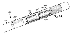
リード100上には、リング電極120とセグメント電極130の任意の組合せを配置することができる。例えば、リードは、第1のリング電極120と、各組が4つのセグメント電極130で構成された2組のセグメント電極と、リードの端部における最終的なリング電極120とを含むことができる。この形態は、単純に1−4−4−1(図3A及び図3E)形態と呼ぶことができる。電極は、この省略表記を用いて呼ぶことが有用となり得る。従って、図3Cの実施形態は1−1−4−4形態と呼ぶことができ、図3Dの実施形態は4−4−1−1形態と呼ぶことができる。図3F及び図3Gの実施形態は、1−3−3−1形態と呼ぶことができる。他の電極形態としては、例えば、4組のセグメント電極をリード上に配置した2−2−2−2形態、各組が4つのセグメント電極230を有する2組のセグメント電極をリード上に配置した4−4形態が挙げられる。図3F及び図3Gの1−3−3−1電極形態は2組のセグメント電極を有し、各組は、リードの円周回り配置された3つの電極を含み、その両側に2つのリング電極(図3F)又はリング電極と先端電極(図3G)が配置される。いくつかの実施形態では、リードが16個の電極を含む。考えられる16電極リードの構成としては、以下に限定されるわけではないが、4−4−4−4、8−8、3−3−3−3−3−1(及びこの形態の全ての再配列)、及び2−2−2−2−2−2−2−2が挙げられる。
An arbitrary combination of the ring electrode 120 and the
図2は、リード200の長さに沿った様々な電極レベルに従う半径方向電流ステアリングを示す概略図である。リング電極を含む在来のリード構成は、リードの長さ(z軸)に沿ってしか電流をステアリングできないが、セグメント電極形態は、x軸、y軸及びz軸に電流をステアリングすることができる。従って、リード200を取り巻く3次元空間の任意の方向に刺激の重心をステアリングすることができる。いくつかの実施形態では、(刺激は、主にカソード近くで発生するが、強いアノードも刺激を引き起こすことができると認識した上で)各電極に導入するアノード電流の割合によって半径方向距離r及びリード200の円周回りの角度θを指示することができる。少なくともいくつかの実施形態では、セグメント電極沿いのアノード及びカソードの形態により、リード200に沿った様々な異なる位置に刺激の重心を変位させることができる。
FIG. 2 is a schematic diagram illustrating radial current steering according to various electrode levels along the length of the
図2から理解できるように、刺激の重心は、リード200の長さに沿って各レベルで変位させることができる。リードの長さに沿って異なるレベルの複数組のセグメント電極を使用することにより、3次元電流ステアリングが可能になる。いくつかの実施形態では、セグメント電極の組が集合的に変位する(すなわち、刺激の重心は、リードの長さに沿った各レベルで同様である)。少なくともいくつかの他の実施形態では、各セグメント電極の組が独立して制御される。各セグメント電極の組は、2つ、3つ、4つ、5つ、6つ、7つ、8つ又はそれ以上のセグメント電極を含む。各レベルのセグメント電極の数を変化させることによって異なる刺激プロファイルが生じることを理解すべきである。例えば、各セグメント電極の組が2つのセグメント電極しか含まない場合、刺激プロファイルには(選択的に刺激できない)均等に分布した間隙が構成される。いくつかの実施形態では、1つの組内で少なくとも3つのセグメント電極230を利用すると、真の360°の選択が可能になる。
As can be seen from FIG. 2, the center of gravity of the stimulus can be displaced at each level along the length of the
上述したように、上記の形態は、記録電極を利用しながら使用することもできる。いくつかの実施形態では、制御ユニット又はマイクロドライブモータシステムに、標的ニューロンによって刺激される筋肉又はその他の組織に結合された測定装置、或いは患者又は臨床医に応答するユニットを結合することができる。測定装置、ユーザ又は臨床医は、標的筋肉又はその他の組織による刺激又は記録電極への応答を示して標的ニューロンをさらに識別し、刺激電極の位置決めを促すことができる。例えば、振戦が生じている筋肉に標的ニューロンを向ける場合には、測定装置を用いて筋肉を観察し、ニューロンの刺激に応答する振戦周波数又は振幅の変化を示すことができる。或いは、患者又は臨床医が筋肉を観察してフィードバックを提供することもできる。 As described above, the above embodiment can also be used while using the recording electrode. In some embodiments, the control unit or microdrive motor system can be coupled to a measurement device coupled to muscle or other tissue stimulated by the target neuron, or a unit responsive to the patient or clinician. A measurement device, user, or clinician can indicate a response to a stimulation or recording electrode by the target muscle or other tissue to further identify the target neuron and prompt the positioning of the stimulation electrode. For example, when a target neuron is directed to a muscle in which tremor is occurring, the measurement device can be used to observe the muscle and indicate changes in tremor frequency or amplitude in response to neuronal stimulation. Alternatively, the patient or clinician can observe the muscle and provide feedback.
リードの信頼性及び耐久性は、設計及び製造法に大きく依存する。後述する製造法は、製造可能な信頼性の高いリードを生産できる方法を提供する。 Lead reliability and durability are highly dependent on design and manufacturing methods. The manufacturing method described later provides a method capable of producing a highly reliable lead that can be manufactured.
再び図1を参照すると、リード100が複数組のセグメント電極130を含む場合には、異なるセグメント電極130の組の対応する電極がリード100の長さに沿って互いに半径方向に整列するようにリード100を構成することが望ましいと考えられる(例えば、図1に示すセグメント電極130を参照)。リード100の長さに沿って異なるセグメント電極130の組の対応する電極同士の半径方向を整列させることにより、異なるセグメント電極の組の対応するセグメント電極同士の位置又は配向に関する不確定要素を減少させることができる。従って、リード100の製造中には、リード100の長さに沿った異なるセグメント電極の組の対応する電極の半径方向を互い整列させるとともに互いに対して半径方向が変位しないように電極アレイを構成することが有利と考えられる。
Referring again to FIG. 1, if the
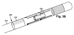
他の実施形態では、2組のセグメント電極130の個々の電極が、リード本体110の長さに沿って互いにずれて配置される(図3Bを参照)。場合によっては、特定用途のために、異なるセグメント電極の組の対応する電極をリード100の長さに沿ってずらして位置付けるように設計することができる。
In other embodiments, the individual electrodes of the two sets of
セグメント電極を使用すると、リング電極を用いて行われるリードの円周回りでの組織の刺激の代わりに、刺激領域を一方向に標的化できるように調整することができる。場合によっては、図2に示すように、リード200の電極を含む平行六面体(又は平板)領域250を標的化することが望ましい。刺激場を平行六面体領域内に向かわせる1つの配列では、リードの両側に配置されたセグメント電極を使用する。
The use of segmented electrodes can be tailored to target the stimulation area in one direction instead of the tissue stimulation around the circumference of the lead performed with a ring electrode. In some cases, it may be desirable to target a parallelepiped (or plate) region 250 containing the electrodes of the
図3A〜図3Gに、セグメント電極330、任意のリング電極320又は先端電極320a、及びリード本体310を含むリード300を示す。セグメント電極330の組は、2つ(図3B)、3つ(図3F及び図3G)、4つ(図3A、図3C及び図3D)、或いは、例えば5つ、6つ又はそれ以上を含む他のいずれかの数の分割電極を含む。
3A-3G show a lead 300 that includes a
他のいずれかの好適なセグメント電極の配列を使用することもできる。一例として、セグメント電極が互いに螺旋状に配置された配列が挙げられる。1つの実施形態は、二重螺旋を含む。 Any other suitable segment electrode arrangement can also be used. As an example, an array in which segment electrodes are arranged in a spiral manner can be given. One embodiment includes a double helix.
半径方向に配置されたセグメント電極の組は、プレ電極から構成することができる。少なくともいくつかの従来のプレ電極は、プレ電極の外周に沿って配置された材料を連結することによって互いに結合された刺激部材を含む。このような従来のプレ電極からセグメント電極を構成する場合には、プレ電極の外周に沿って配置された連結材料を摩滅させて刺激部材を互いに物理的に分離し、電気的に絶縁されたセグメント電極を構成する。 The set of segment electrodes arranged in the radial direction can be composed of pre-electrodes. At least some conventional pre-electrodes include stimulating members that are coupled together by connecting materials disposed along the perimeter of the pre-electrode. When a segment electrode is constructed from such a conventional pre-electrode, the connecting material disposed along the outer periphery of the pre-electrode is worn away to physically separate the stimulating members from each other, thereby electrically insulating segments. Configure the electrode.
本明細書で説明したように、プレ電極は、刺激部材を互いに物理的に分離して電気的に絶縁されたセグメント電極を構成するように、製造中に除去できる中心ハブを介して互いに結合された刺激部材を含む。少なくともいくつかの実施形態では、刺激部材の各々が、中心ハブのみを介して残りの刺激部材の各々に電気的に結合される。換言すれば、少なくともいくつかの実施形態では、プレ電極が、プレ電極の外周に沿って配置された、隣接する刺激部材同士を結合する連結材料を含まない。従って、中心ハブを除去することのみによって刺激部材間の電気的絶縁を得ることができる。 As described herein, the pre-electrodes are coupled together through a central hub that can be removed during manufacturing to physically separate the stimulation members from each other to form an electrically insulated segment electrode. A stimulating member. In at least some embodiments, each of the stimulation members is electrically coupled to each of the remaining stimulation members only through the central hub. In other words, in at least some embodiments, the pre-electrode does not include a linking material that joins adjacent stimulation members disposed along the periphery of the pre-electrode. Therefore, electrical insulation between the stimulating members can be obtained only by removing the central hub.
本明細書で説明するプレ電極、及びこれらのプレ電極から構成されるセグメント電極は、金属、合金、導電性酸化物又はその他のいずれかの好適な導電性材料などの導電体で構成することができる。いくつかの実施形態では、プレ電極が、プラチナ、プラチナイリジウム、イリジウム、616Lステンレス鋼(又はその他のいずれかの好適なステンレス鋼)、タンタル、ニチノール、イリジウムロジウム、又は導電性ポリマーで構成される。 The pre-electrodes described herein and the segment electrodes comprised of these pre-electrodes may be comprised of a conductor such as a metal, alloy, conductive oxide or any other suitable conductive material. it can. In some embodiments, the pre-electrode is comprised of platinum, platinum iridium, iridium, 616L stainless steel (or any other suitable stainless steel), tantalum, nitinol, iridium rhodium, or a conductive polymer.
図4Aに、半径方向に配置されたセグメント電極の組の構成において使用するのに適したプレ電極400の一実施形態を横断面図で概略的に示す。図4Bには、プレ電極400の一実施形態を斜視図で概略的に示す。プレ電極400は、近位端部404、遠位端部406及び長手方向長さ408を有する本体402含む。
FIG. 4A schematically illustrates in cross-sectional view one embodiment of a pre-electrode 400 suitable for use in the configuration of a radially arranged segment electrode set. FIG. 4B schematically illustrates one embodiment of the pre-electrode 400 in a perspective view.
本体402は、長手方向面424を有する中心ハブ414を含む。刺激部材418a、418b、418cはそれぞれ、中心ハブ414の長手方向面424から半径方向に延びる連結要素422a、422b、422cを介して中心ハブ414に結合される。図4A及び図4B(及び他の図)には、単一の連結要素422a、422b、422cによってそれぞれ中心ハブ414に結合された刺激部材418a、418b、418cを示している。少なくともいくつかの実施形態では、刺激部材418a、418b、418cのうちの少なくとも1つは、複数の連結要素422a、422b、422cによって中心ハブ414に結合される。
The
中心ハブ414は、任意の好適な寸法及び形状とすることができる。図4A及び図4Bには、中心ハブ414を、ハブ孔416を含むチューブ形状として示している。中心ハブ414は、中心ハブ414の長手方向面424の周囲に非導電性材料が配置されていて(例えば、図9Aを参照)中心ハブ414を除去した(例えば、図9Bを参照)時に、元々中心ハブ414によって占められていた位置に構成される中心内腔の寸法及び形状が、リードの長手方向長さに沿って延びてリードの埋込み中にスタイレット(図1の140)を受入れる軸方向に配置されたスタイレット内腔(図示せず)に類似するように、管状として又は実質的に管状として構成することが有利と考えられる。
The
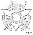
連結要素422a、422b、422cは、本体402の長手方向長さ408全体に沿って延びていてもよいし、長手方向長さ408の一部のみに沿って延びていてもよい。少なくともいくつかの実施形態では、連結要素422a、422b、422cが、中心ハブ414の外周回りで等間隔を空けるように中心ハブ414の長手方向面424に結合される。例えば、図4Aには、連結要素422a、422b、422cを、中心ハブ414の円周回りで、残りの2つの連結要素から各々120°離れたものとして示している。別の例として、図8には、4つの連結要素822a、822b、822c、822dを、中心ハブ814の円周回りで、隣接する2つの連結要素から各々90°離れたものとして示している。
The
プレ電極400の本体402は、任意の好適な形状とすることができる。少なくともいくつかの実施形態では、本体402が実質的に円筒形であり、刺激部材418a、418b、418cが本体402の外周を構成する。いくつかの実施形態では、セグメント電極の動作中に、刺激部材418a、418b、418cの外面426a、426b、426cがセグメント電極の外面を構成する(例えば、図9Cを参照)。他の実施形態では、刺激部材418a、418b、418cの外面426a、426b、426cを、電気的に絶縁されたセグメント電極として動作する前に摩滅させる。
The
プレ電極400の本体402は、任意の好適な寸法とすることができる。少なくともいくつかの実施形態では、本体402が、プレ電極を配置すべきリードの遠位端部分(例えば、図1の110を参照)の直径に等しい、又は実質的に等しい直径を有する。
The
刺激部材418a、418b、418cは、本体402の長手方向長さ408の全体に沿って延びていてもよいし、一部のみに沿って延びていてもよい。刺激部材418a、418b、418cの各々はそれぞれ、外面426a、426b、426cと、内面428a、428b、428cを含む。少なくともいくつかの実施形態では、連結要素422a、422b、422cはそれぞれ、刺激部材418a、418b、418cの内面428a、428b、428cに沿って、それぞれ刺激部材418a、418b、418cに結合される。
The
刺激部材418a、418b、418cの外面426a、426b、426cは、任意の好適な形状とすることができる。少なくともいくつかの実施形態では、刺激部材418a、418b、418cが円弧状であり、外面426a、426b、426cが凸状であり、内面428a、428b、428cが凹状である。少なくともいくつかの実施形態では、プレ電極を配置すべきリードの横断面(例えば、図9B及び図9Cの952を参照)と同様の弧が外面426a、426b、426cによって描かれるように、刺激部材418a、418b、418cが弧を描く。
The
通常、プレ電極400から構成されたセグメント電極(例えば、図9B及び図9Cの918a、918b、918cを参照)を通過する刺激エネルギーは、導体430a、430b、430c等の導体を介してセグメント電極に供給される。導体430a、430b、430cは、プレ電極400の刺激部材418a、418b、418cに、又は刺激部材418a、418b、418cから構成されたセグメント電極(例えば、図9B及び図9Cの918a、918b、918cを参照)に結合することができる。導体430a、430b、430cは、刺激部材418a、418b、418c(又はこれらによって構成されるセグメント電極)にアクセスするために非導電性材料の一部を後から除去しなくて済むように、中心ハブ414の周囲に非導電性材料を配置する前に刺激部材418a、418b、418cに結合することが有利と考えられる。
Usually, the stimulation energy passing through the segment electrode composed of the pre-electrode 400 (see, for example, 918a, 918b, and 918c in FIGS. 9B and 9C) is transmitted to the segment electrode through conductors such as
図4Aには、刺激部材418a、418b、418cの内面428a、428b、428cにそれぞれ結合された導体430a、430b、430cを示している。これとは別に、又はこれに加えて、導体430a、430b、430cのうちの1つ又はそれ以上を、刺激部材418a、418b、418cの内面428a、428b、428cにそれぞれ結合する代わりに、又はこれに加えて、連結要素422a、422b、422cのうちの1つ又はそれ以上にそれぞれ結合することもできる。
FIG. 4A shows
図5〜図7を参照すると、製造工程中、中心ハブの長手方向面の周囲には非導電性材料が配置される。非導電性材料は、刺激部材の内面が非導電性材料で覆われるように中心ハブから刺激部材まで半径方向外向きに広がる。いくつかの実施形態では、非導電性材料が、非導電性材料の外面(長手方向面)が刺激部材の外面と同一平面を成すように中心ハブから刺激部材まで半径方向外向きに広がる。 Referring to FIGS. 5-7, a non-conductive material is disposed around the longitudinal surface of the central hub during the manufacturing process. The non-conductive material extends radially outward from the central hub to the stimulation member such that the inner surface of the stimulation member is covered with the non-conductive material. In some embodiments, the non-conductive material extends radially outward from the central hub to the stimulation member such that the outer surface (longitudinal surface) of the non-conductive material is flush with the outer surface of the stimulation member.
非導電性材料は、例えば射出成形、ポリマー材料のリフローなどを含む任意の好適な方法で中心ハブの長手方向面上に配置することができる。プレ電極は、刺激部材418a、418b、418cのうちの1つ又はそれ以上、連結要素422a、422b、422cのうちの1つ又はそれ以上、或いはこれらの両方に沿って配置された1又はそれ以上のリード保持特徴部を選択的に含む。この1又はそれ以上のリード保持特徴部は、プレ電極(及びプレ電極によって構成されたセグメント電極)に対する非導電性材料の接着を促すために使用することができる。また、プレ電極からセグメント電極が形成されると、1又はそれ以上のリード保持特徴部は、非導電性材料に対するセグメント電極の接着を促すことに加え、セグメント電極間の相対的位置及び物理的分離(及び電気的絶縁)の維持を促すこともできる。
The non-conductive material can be placed on the longitudinal surface of the central hub in any suitable manner including, for example, injection molding, reflow of polymer material, and the like. The pre-electrode may be one or more of the
図5に、プレ電極400に沿って配置されたリード保持特徴部502の一実施形態を横断面図で概略的に示す。図5では、リード保持特徴部502が、刺激部材418a、418b、418cの内面428a、428b、428cからそれぞれ延びる引掛り部506として構成されている。引掛り部506は、刺激部材418a、418b、418cの内面428a、428b、428cの任意の好適な部分に沿って配置することができる。図5には、刺激部材418a、418b、418cの内面428a、428b、428cの両端部から延びる引掛り部506を示している。引掛り部506は、刺激部材418a、418b、418cと同じ材料によって構成されてもよいし、異なる材料によって構成されてもよい。
FIG. 5 schematically illustrates in cross-section one embodiment of a
プレ電極400上には、例えば1、2、3、4、5、6、7、8、9、10、11、12、15又はそれ以上の引掛り部506を含む任意の好適な数の引掛り部506を配置することができる。少なくともいくつかの実施形態では、刺激部材418a、418b、418cの各々に少なくとも1つの引掛り部506が配置される。少なくともいくつかの実施形態では、刺激部材418a、418b、418cの各々に少なくとも2つの引掛り部506が配置される。少なくともいくつかの実施形態では、刺激部材418a、418b、418cの各々に同じ数の引掛り部506が配置される。
Any suitable number of hooks including, for example, 1, 2, 3, 4, 5, 6, 7, 8, 9, 10, 11, 12, 15 or
図6に、プレ電極400に沿って配置されたリード保持特徴部602の別の実施形態を横断面図で概略的に示す。図6では、リード保持特徴部602が、連結要素422a、422b、422cから延びる引掛り部606として構成されている。引掛り部606は、連結要素422a、422b、422cの任意の好適な部分に沿って配置することができる。図6には、連結要素422a、422b、422cの長さに沿って連結要素422a、422b、422cの両側から延びる引掛り部606を示している。引掛り部606は、連結要素422a、422b、422cと同じ材料によって構成されてもよいし、異なる材料によって構成されてもよい。
FIG. 6 schematically illustrates another embodiment of a
プレ電極400上には、例えば1、2、3、4、5、6、7、8、9、10、11、12、15又はそれ以上の引掛り部606を含む任意の好適な数の引掛り部606を配置することができる。少なくともいくつかの実施形態では、連結要素422a、422b、422cの各々に少なくとも1つの引掛り部606が配置される。少なくともいくつかの実施形態では、連結要素422a、422b、422cの各々に少なくとも2つの引掛り部606が配置される。少なくともいくつかの実施形態では、連結要素422a、422b、422cの各々の各側面に少なくとも1つの引掛り部606が配置される。少なくともいくつかの実施形態では、連結要素422a、422b、422cの各々に同じ数の引掛り部606が配置される。
Any suitable number of hooks including, for example, 1, 2, 3, 4, 5, 6, 7, 8, 9, 10, 11, 12, 15 or
図7に、プレ電極400に沿って配置されたリード保持特徴部702の一実施形態を横断面図で概略的に示す。図7では、リード保持特徴部702が、刺激部材418a、418b、418cの少なくとも1つの長手方向縁部に沿って構成されたアンダーカット部706として構成されている。図7には、刺激部材418a、418b、418cの両端部に沿って構成されたアンダーカット部706を示している。
FIG. 7 schematically illustrates one embodiment of a
プレ電極400上には、例えば1つ、2つ、3つ、4つ、5つ、6つ又はそれ以上のアンダーカット部706を含む任意の好適な数のアンダーカット部706を配置することができる。少なくともいくつかの実施形態では、刺激部材418a、418b、418cの各々に少なくとも1つのアンダーカット部706が配置される。少なくともいくつかの実施形態では、刺激部材418a、418b、418cの各々に少なくとも2つのアンダーカット部706が配置される。少なくともいくつかの実施形態では、刺激部材418a、418b、418cの各々に同じ数のアンダーカット部706が配置される。
Any suitable number of
図5〜図7(及び他の図)に示すリード保持特徴部は、任意の好適な組合せで使用できることを理解すべきである。例えば、プレ電極は、(刺激部材のうちの1つ又はそれ以上に沿って配置された、又は連結要素のうちの1つ又はそれ以上に沿って配置された)アンダーカット部及び引掛り部を有することもできる。別の例として、プレ電極は、アンダーカット部を有さずに、刺激部材及び1又はそれ以上の連結要素の両方に沿って配置された引掛り部を有することもできる。 It should be understood that the lead retention features shown in FIGS. 5-7 (and other figures) can be used in any suitable combination. For example, the pre-electrode has undercuts and catches (arranged along one or more of the stimulation members or arranged along one or more of the connecting elements). Can also have. As another example, the pre-electrode may have a hook portion that is disposed along both the stimulating member and one or more connecting elements without having an undercut portion.
図4A〜図7(及び他の図)には、3つの刺激部材を有するプレ電極を示している。プレ電極は、例えば2つ、3つ、4つ、5つ、6つ、7つ、8つ又はそれ以上の刺激部材を含む任意の好適な数の刺激部材を含むことができることを認識すべきである。図8に、4つの刺激部材818a、818b、818c、818dを有する本体802を含むプレ電極400の一実施形態を横断面図で概略的に示す。本体802は、長手方向面824を有する中心ハブ814を含む。刺激部材818a、818b、818c、818dはそれぞれ、中心ハブ814の長手方向面824から半径方向に延びる連結要素822a、822b、822c、822dを介して中心ハブ814に結合される。図示の刺激部材818a、818b、818c、818dの各々は、単一の連結要素822a、822b、822c、822dによって中心ハブ414に結合される。少なくともいくつかの実施形態では、刺激部材818a、818b、818c、818dのうちの少なくとも1つが、複数の連結要素822a、822b、822c、822dによって中心ハブ814に結合される。
4A-7 (and other figures) show a pre-electrode having three stimulation members. It should be appreciated that the pre-electrode can include any suitable number of stimulation members including, for example, two, three, four, five, six, seven, eight or more stimulation members. It is. FIG. 8 schematically illustrates in cross-sectional view one embodiment of a pre-electrode 400 that includes a body 802 having four
図9A〜9Cを参照すると、通常、プレ電極は、リードの遠位端部分に沿って配置され、中心ハブを除去して各刺激部材(及びこれらが取付けられた各連結要素)を互いに電気的に絶縁することにより、セグメント電極が構成される。図9A〜図9Cの各々には、図5のプレ電極を示している。本明細書で説明するプレ電極の各々には、リード上にプレ電極を配置する技術、並びに刺激部材(及びこれらが取付けられた連結要素)を電気的に絶縁してセグメント電極を構成する技術を適用することができることを理解すべきである。 Referring to FIGS. 9A-9C, typically, the pre-electrode is placed along the distal end portion of the lead to remove the central hub and electrically connect each stimulation member (and each connecting element to which they are attached) to each other. The segment electrode is formed by insulating the electrodes. Each of FIGS. 9A to 9C shows the pre-electrode of FIG. Each of the pre-electrodes described in this specification includes a technique for arranging a pre-electrode on a lead, and a technique for forming a segment electrode by electrically insulating a stimulating member (and a connecting element to which these are attached). It should be understood that it can be applied.
図9Aに、プレ電極400の中心ハブ414の周囲に半径方向に配置された非導電性材料902の一実施形態を横断面図で概略的に示す。非導電性材料902は、中心ハブ414の長手方向面424、並びに連結要素422a、422b、422cを覆う。また、非導電性材料902は、刺激部材418a、418b、418cのそれぞれの内面428a、428b、428cに当接する。少なくともいくつかの実施形態では、非導電性材料902が、刺激部材418a、418b、418cのそれぞれの外面426a、426b、426cが非導電性材料902の長手方向面954と同一平面又はほぼ同一平面を成すように中心ハブ414の周囲に配置される。
FIG. 9A schematically illustrates, in cross-sectional view, one embodiment of a
任意の好適な生体適合性のある非導電性材料を使用することができる。少なくともいくつかの実施形態では、非導電性材料はポリマー材料である。少なくともいくつかの実施形態では、非導電性材料は、リード本体を構成するために使用される材料と同じ材料(又は同様の材料)(例えば、ポリウレタン、シリコン、接着剤など、又はこれらの組合せ)である。非導電性材料902は、例えば射出成形、リフローなどを含む任意の好適な方法で中心ハブ414の長手方向面424を覆って配置される。
Any suitable biocompatible non-conductive material can be used. In at least some embodiments, the non-conductive material is a polymeric material. In at least some embodiments, the non-conductive material is the same material (or similar material) as used to construct the lead body (eg, polyurethane, silicone, adhesive, etc., or combinations thereof). It is. The
図9Aには、刺激部材418a、418b、418cにそれぞれ結合された導体430a、430b、430cを示している。上述したように、導体430a、430b、430cは、中心ハブ414の周囲に非導電性材料を配置する前又は後に、刺激部材418a、418b、418c(又はこれらが取付られたけ連結要素)に結合することができる。
FIG. 9A shows
プレ電極は、例えば非導電性材料のリフロー、リード本体の材料のリフロー(又は両方)、非導電性材料及びリード本体の材料の両方のリフロー、接着剤の付与など、又はこれらの組合せを含む任意の好適な方法でリード本体の端部に取付けることができる。或いは、リード本体と、中心ハブの周囲に配置された非導電性材料とが単一構造として構成されるように、セグメント電極の構成と同時にリード本体を構成することもできる。少なくともいくつかの実施形態では、リードが、複数組のセグメント電極(或いはリング電極又は先端電極)を含むことができる。この場合、軸方向に隣接するプレ電極(或いはリング電極又は先端電極)間に非導電性材料を軸方向に配置して、複数のプレ電極を所望の軸構成で配置することができる。 Any pre-electrode includes, for example, non-conductive material reflow, lead body material reflow (or both), non-conductive material and lead body material reflow, adhesive application, etc., or combinations thereof It can be attached to the end of the lead body by a suitable method. Alternatively, the lead body can be configured simultaneously with the segment electrodes so that the lead body and the non-conductive material disposed around the central hub are configured as a single structure. In at least some embodiments, the lead can include multiple sets of segment electrodes (or ring electrodes or tip electrodes). In this case, it is possible to dispose a plurality of pre-electrodes in a desired axial configuration by disposing a non-conductive material in the axial direction between pre-electrodes (or ring electrodes or tip electrodes) adjacent in the axial direction.
中心ハブの周囲に非導電性材料を配置したら、中心ハブを除去することができる。プレ電極の中心ハブを除去したら、残りの電気的に絶縁された刺激部材及びこれらの対応する連結要素は、セグメント電極と呼ばれるようになる。中心ハブを除去することにより、少なくとも1つの連結要素の少なくとも一部も除去することができる。 Once the non-conductive material is placed around the central hub, the central hub can be removed. Once the central hub of the pre-electrode is removed, the remaining electrically isolated stimulation members and their corresponding connecting elements will be referred to as segment electrodes. By removing the central hub, at least a portion of the at least one connecting element can also be removed.
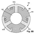
図9Bに、リード952の遠位端部分の一実施形態を横断面図で概略的に示す。リード952は、非導電性材料902と、プレ電極400の中心ハブ414を除去することによってプレ電極400から構成されたセグメント電極918a、918b、918cをと含む。中心ハブ414を除去すると、非導電性材料902内の、中心ハブ414が除去前に存在していたリード952沿いの位置に、中心内腔940が構成されるようになる。
FIG. 9B schematically illustrates one embodiment of the distal end portion of the
中心ハブ414の除去は、任意の好適な方法で行うことができる。少なくともいくつかの実施形態では、(例えばドリルなどで)中心ハブ414に孔をくり抜く。例えば、リード952の中心ハブ414を含む部分にドリルを通過させることができる。少なくともいくつかの実施形態では、リード952の遠位端部にドリルを通し、プレ電極の長手方向長さ(図4Bの408)を貫通させる。このような方法で中心ハブ414に孔をくり抜くことにより、元々中心ハブ414によって占められていた空間に加え、リードの遠位端部分に沿って中心内腔940を構成することができる。リードの遠位端部にドリルを通す少なくともいくつかの実施形態では、その後に遠位端部に蓋をかぶせ、又はその後に遠位端部に沿って先端電極を配置する。
Removal of the
少なくともいくつかの実施形態では、リード本体が、スタイレット(図1の140)を受入れるためのスタイレット内腔を含む。プレ電極は、中心ハブ414がスタイレット内腔と軸方向に整列し、スタイレット内腔に対して開口するようにリード本体上に配置することができる。このような構成により、埋込み中に中心内腔940にスタイレットを導入できるようになる。ドリルによって中心ハブを除去する場合、及び中心ハブをスタイレット内腔と軸方向に整列させ、スタイレット内腔に対して開口させる場合、少なくともいくつかの実施形態では、スタイレット内腔の少なくとも一部に沿ってドリルを通すことができる。
In at least some embodiments, the lead body includes a stylet lumen for receiving a stylet (140 in FIG. 1). The pre-electrode can be placed on the lead body such that the
図9Bに示すように、プレ電極から中心ハブを除去する際には、セグメント電極の1又はそれ以上の部分(例えば、セグメント電極の1又はそれ以上の連結要素部分)が中心内腔940に物理的に露出することがある。例えば、動作中に時間と共に中心内腔に体液が入り込むことによって引き起こされる望ましくない短絡の可能性を防ぐために、セグメント電極の一部が中心内腔940に物理的に露出するのを避けることが望ましいと考えられる。少なくともいくつかの実施形態では、リード本体の遠位端部分において、リードの本体と中心内腔940との間に絶縁材料が配置される。この絶縁材料は非導電性であり、セグメント電極を中心内腔940から電気的に絶縁するように機能する。
As shown in FIG. 9B, when removing the central hub from the pre-electrode, one or more portions of the segment electrode (eg, one or more connecting element portions of the segment electrode) are physically attached to the
図9Cに、リード952の遠位端部分の一実施形態を横断面図で概略的に示す。リード952は、中心内腔940と、プレ電極400から構成されたセグメント電極918a、918b、918cとを含む。図9Cに示すセグメント電極918a、918b、918cは、プレ電極400の刺激部材418a、418b、418cと、これらが取付けられた連結要素422a、422b、422cとを含む。刺激部材418a、418b、418cは、(図9Aに示す)外面426a、426b、426cと、その反対側の内面428a、428b、428cとを含む。
FIG. 9C schematically illustrates one embodiment of the distal end portion of the
セグメント電極918a、918b、918cのそれぞれの外面426a、426b、426cは、非導電性材料902の長手方向面954に沿って露出する。少なくともいくつかの実施形態では、セグメント電極918a、918b、918cの外面426a、426b、426c、及び/又は非導電性材料902の長手方向面954を、これらが互いに同一平面を成すように摩滅させることができる。
The respective
少なくともいくつかの実施形態では、プレ電極の中心ハブを除去した後、セグメント電極の連結要素部分の各々が、リードの半径の少なくとも20%、30%、40%、50%、60%、70%又はそれ以上に沿って延びる。上述したように、中心ハブを除去すると、セグメント電極の連結要素部分が中心内腔940に物理的に露出することがある。
In at least some embodiments, after removing the central hub of the pre-electrode, each of the segment electrode connecting element portions is at least 20%, 30%, 40%, 50%, 60%, 70% of the radius of the lead. Or extend beyond. As described above, removal of the central hub may physically expose the segment electrode coupling element portion to the
少なくともいくつかの実施形態では、セグメント電極918a、918b、918cを中心内腔940から電気的に絶縁するために、中心内腔940の長手方向壁の少なくとも一部に沿って絶縁材料960を配置する。少なくともいくつかの実施形態では、中心内腔940の長手方向壁の少なくとも一部に沿って絶縁材料960を配置すると、セグメント電極918a、918b、918cの連結要素部分が、絶縁材料960に物理的に当接する。
In at least some embodiments, an insulating
絶縁材料960は、例えばポリウレタン、シリコン、接着剤など、又はこれらの組合せを含む任意の好適な非導電性材料によって構成される。少なくともいくつかの実施形態では、絶縁材料960は、非導電性材料902と異なる材料によって構成される。少なくともいくつかの実施形態では、絶縁材料960は、リード本体を構成するために使用される非導電性材料と異なる材料によって構成される。少なくともいくつかの実施形態では、絶縁材料960が、非導電性材料902又はリード本体を構成するために使用される材料とは異なる材料によって構成される。
Insulating
絶縁材料960は、任意の好適な技術を用いて中心内腔940の長手方向壁に適用することができる。少なくともいくつかの実施形態では、絶縁材料960が、中心内腔940に挿入されて中心内腔940の壁と共にリフローされたライナとして構成される。絶縁材料960を適用するための他の技術としては、例えば射出成形、化学蒸着などを挙げることができる。
Insulating
上記の明細書、実施例及びデータは、本発明の構成の製造及び使用を説明するものである。本発明の思想及び範囲から逸脱することなく多くの実施形態を構成できるので、本発明は、以下に添付する特許請求の範囲に帰する。 The above specification, examples and data illustrate the manufacture and use of the composition of the invention. Since many embodiments can be made without departing from the spirit and scope of the invention, the invention resides in the claims hereinafter appended.
Claims (20)
少なくとも1つのプレ電極をリード本体の遠位端部分に沿って配置するステップを含み、前記少なくとも1つのプレ電極は、プレ電極本体を含み、前記プレ電極本体は、近位端部と、遠位端部と、導電性の中心ハブと、前記中心ハブに個別に結合され且つ前記中心ハブから半径方向外向きに延びる複数の導電性刺激部材とを有し、前記複数の導電性刺激部材の各々は、残りの前記複数の導電性刺激部材の各々に前記中心ハブのみを介して電気的に結合され、
更に、前記リード本体の近位端部分に沿って配置された複数の端子から延びる複数の導体のうちの少なくとも1つの導体を前記複数の刺激部材の各々に電気的に結合させるステップと、
非導電性材料を前記中心ハブの長手方向面の周囲に配置して、前記非導電性材料を前記複数の導電性刺激部材の内面に当接させるステップと、
前記中心ハブを前記プレ電極本体から除去して前記複数の導電性刺激部材の各々を互いに電気的に絶縁し、それにより、前記複数の導電性刺激部材を、前記非導電性材料に沿って配置され且つ電気的に絶縁された複数のセグメント電極に変換するステップと、を含む方法。 A method of creating a stimulation lead,
Disposing at least one pre-electrode along a distal end portion of the lead body, the at least one pre-electrode including a pre-electrode body, the pre-electrode body including a proximal end and a distal end; Each of the plurality of conductive stimulation members having an end portion, a conductive central hub, and a plurality of conductive stimulation members individually coupled to the central hub and extending radially outward from the central hub. Is electrically coupled to each of the remaining plurality of conductive stimulation members only through the central hub,
Electrically coupling at least one of a plurality of conductors extending from a plurality of terminals disposed along a proximal end portion of the lead body to each of the plurality of stimulation members;
Placing a non-conductive material around a longitudinal surface of the central hub to abut the non-conductive material against the inner surfaces of the plurality of conductive stimulation members;
The central hub is removed from the pre-electrode body to electrically insulate each of the plurality of conductive stimulation members from each other, thereby disposing the plurality of conductive stimulation members along the non-conductive material And converting to a plurality of electrically insulated segment electrodes.
実質的に円筒形のプレ電極本体を有し、
前記プレ電極本体は、近位端部と、遠位端部と、長手方向面を有する導電性の中心ハブと、前記中心ハブの長手方向面から半径方向外向きに延びる複数の連結要素と、を有し、前記複数の連結要素の各々は、前記中心ハブに結合された内側端部と、その両側の外側端部を有し、
前記プレ電極本体は、更に、複数の刺激部材を有し、前記複数の刺激部材の各々は、内面と、外面を有し、前記複数の刺激部材の各々の内面は、前記複数の連結要素のうちの少なくとも1つの連結要素の内側端部に結合され、前記複数の刺激部材の各々は、前記複数の刺激部材のうちの残りの刺激部材の各々に前記中心ハブのみを介して電気的に結合される、プレ電極。 A pre-electrode for the stimulation lead,
Having a substantially cylindrical pre-electrode body;
The pre-electrode body includes a proximal end, a distal end, a conductive central hub having a longitudinal surface, and a plurality of connecting elements extending radially outward from the longitudinal surface of the central hub; Each of the plurality of connecting elements has an inner end coupled to the central hub and outer ends on opposite sides thereof.
The pre-electrode body further includes a plurality of stimulation members, each of the plurality of stimulation members includes an inner surface and an outer surface, and each inner surface of the plurality of stimulation members includes the plurality of connection elements. Coupled to the inner end of at least one of the coupling elements, each of the plurality of stimulation members electrically coupled to each of the remaining stimulation members of the plurality of stimulation members only through the central hub A pre-electrode.
リード本体材料によって構成されたリード本体を有し、前記リード本体は、長手方向面と、遠位端部分と、近位端部分と、長手方向長さを含み、
更に、前記リード本体の長手方向長さに沿って延び、且つ、長手方向壁によって境界が定められる中心内腔と、
前記リード本体の前記遠位端部分に且つ前記リード本体と前記中心内腔との間に配置され、且つ、前記リード本体材料と異なる材料である絶縁材料と、
前記リード本体の近位端部分に沿って配置された複数の端子と、
前記リード本体の遠位端部分に沿って配置された複数の電極と、
前記複数の端子を前記複数の電極に電気的に結合させる複数の導体と、を有し、
前記複数の電極は、複数のセグメント電極を含み、前記複数のセグメント電極の各々は、外面及びその反対側の内面を有する刺激部材と、前記刺激部材の内面に結合され且つ前記絶縁材料まで半径方向内向きに延びる連結要素と、を含む刺激リード。 A stimulation lead,
A lead body made of a lead body material, the lead body including a longitudinal surface, a distal end portion, a proximal end portion, and a longitudinal length;
A central lumen extending along a longitudinal length of the lead body and delimited by a longitudinal wall;
An insulating material disposed at the distal end portion of the lead body and between the lead body and the central lumen and being a different material from the lead body material;
A plurality of terminals disposed along a proximal end portion of the lead body;
A plurality of electrodes disposed along a distal end portion of the lead body;
A plurality of conductors that electrically couple the plurality of terminals to the plurality of electrodes;
The plurality of electrodes includes a plurality of segment electrodes, each of the plurality of segment electrodes being coupled to the stimulation member inner surface and a stimulation member having an outer surface and an inner surface opposite thereto, and radially to the insulating material A stimulating lead comprising an inwardly extending connecting element.
Applications Claiming Priority (3)
| Application Number | Priority Date | Filing Date | Title |
|---|---|---|---|
| US201361845739P | 2013-07-12 | 2013-07-12 | |
| US61/845,739 | 2013-07-12 | ||
| PCT/US2014/045618 WO2015006239A1 (en) | 2013-07-12 | 2014-07-07 | Leads with segmented electrodes and methods of making and using the leads |
Publications (2)
| Publication Number | Publication Date |
|---|---|
| JP2016524960A JP2016524960A (en) | 2016-08-22 |
| JP6072986B2 true JP6072986B2 (en) | 2017-02-01 |
Family
ID=51230206
Family Applications (1)
| Application Number | Title | Priority Date | Filing Date |
|---|---|---|---|
| JP2016525405A Expired - Fee Related JP6072986B2 (en) | 2013-07-12 | 2014-07-07 | Lead having segment electrode and method of manufacturing and using lead |
Country Status (6)
| Country | Link |
|---|---|
| US (1) | US9289596B2 (en) |
| EP (1) | EP3019232B1 (en) |
| JP (1) | JP6072986B2 (en) |
| CN (1) | CN105377360A (en) |
| AU (1) | AU2014287516A1 (en) |
| WO (1) | WO2015006239A1 (en) |
Families Citing this family (114)
| Publication number | Priority date | Publication date | Assignee | Title |
|---|---|---|---|---|
| US7860570B2 (en) | 2002-06-20 | 2010-12-28 | Boston Scientific Neuromodulation Corporation | Implantable microstimulators and methods for unidirectional propagation of action potentials |
| US8321025B2 (en) | 2006-07-31 | 2012-11-27 | Cranial Medical Systems, Inc. | Lead and methods for brain monitoring and modulation |
| EP2313148B1 (en) | 2008-07-30 | 2013-08-21 | Ecole Polytechnique Fédérale de Lausanne | Apparatus for optimized stimulation of a neurological target |
| CA2743575C (en) | 2008-11-12 | 2017-01-31 | Ecole Polytechnique Federale De Lausanne | Microfabricated neurostimulation device |
| EP2552536B1 (en) | 2010-04-01 | 2016-06-08 | Ecole Polytechnique Fédérale de Lausanne (EPFL) | Device for interacting with neurological tissue |
| US9919148B2 (en) | 2012-05-25 | 2018-03-20 | Boston Scientific Neuromodulation Corporation | Distally curved electrical stimulation lead and methods of making and using |
| WO2014145222A2 (en) | 2013-03-15 | 2014-09-18 | Boston Scientific Neuromodulation Corporation | Systems and methods for delivering sub-threshold therapy to a patient |
| AU2014265854A1 (en) | 2013-05-15 | 2015-11-12 | Boston Scientific Neuromodulation Corporation | Systems and methods for making tip electrodes for leads of electrical stimulation systems |
| US9775988B2 (en) | 2013-12-02 | 2017-10-03 | Boston Scientific Neuromodulation Corporation | Electrical stimulation leads with helically arranged electrodes and methods of making and using |
| CN106455985B (en) | 2014-05-16 | 2019-09-17 | 阿莱瓦神经治疗股份有限公司 | With the device and production and preparation method thereof of nerve fiber interaction |
| US11311718B2 (en) | 2014-05-16 | 2022-04-26 | Aleva Neurotherapeutics Sa | Device for interacting with neurological tissue and methods of making and using the same |
| JP2017517374A (en) | 2014-06-13 | 2017-06-29 | ボストン サイエンティフィック ニューロモデュレイション コーポレイション | Lead having an electrode carrier for a segment electrode and method for manufacturing and using the same |
| US9474894B2 (en) | 2014-08-27 | 2016-10-25 | Aleva Neurotherapeutics | Deep brain stimulation lead |
| US9770598B2 (en) | 2014-08-29 | 2017-09-26 | Boston Scientific Neuromodulation Corporation | Systems and methods for making and using improved connector contacts for electrical stimulation systems |
| US10569039B2 (en) | 2014-09-17 | 2020-02-25 | Richard M. Levitan | Introducer for tracheal tube intubation |
| US9604068B2 (en) | 2014-11-10 | 2017-03-28 | Boston Scientific Neuromodulation Corporation | Systems and methods for making and using improved connector contacts for electrical stimulation systems |
| US9561362B2 (en) | 2014-11-10 | 2017-02-07 | Boston Scientific Neuromodulation Corporation | Systems and methods for making and using improved contact arrays for electrical stimulation systems |
| US10286205B2 (en) | 2015-02-06 | 2019-05-14 | Boston Scientific Neuromodulation Corporation | Systems and methods for making and using improved contact arrays for electrical stimulation systems |
| WO2016164361A1 (en) | 2015-04-10 | 2016-10-13 | Boston Scientific Neuromodulation Corporation | Systems and methods for making and using improved contact arrays for electrical stimulation systems |
| WO2017003947A1 (en) | 2015-06-29 | 2017-01-05 | Boston Scientific Neuromodulation Corporation | Systems and methods for selecting stimulation parameters by targeting and steering |
| EP3280490B1 (en) | 2015-06-29 | 2021-09-01 | Boston Scientific Neuromodulation Corporation | Systems for selecting stimulation parameters based on stimulation target region, effects, or side effects |
| US9656093B2 (en) * | 2015-07-16 | 2017-05-23 | Boston Scientific Neuromodulation Corporation | Systems and methods for making and using connector contact arrays for electrical stimulation systems |
| EP3307382A1 (en) | 2015-08-24 | 2018-04-18 | Boston Scientific Neuromodulation Corporation | Systems and methods for determining orientation of an electrical stimulation lead |
| WO2017040573A1 (en) | 2015-09-01 | 2017-03-09 | Boston Scientific Neuromodulation Corporation | Detection of lead orientation |
| US9956394B2 (en) | 2015-09-10 | 2018-05-01 | Boston Scientific Neuromodulation Corporation | Connectors for electrical stimulation systems and methods of making and using |
| US10413737B2 (en) | 2015-09-25 | 2019-09-17 | Boston Scientific Neuromodulation Corporation | Systems and methods for providing therapy using electrical stimulation to disrupt neuronal activity |
| WO2017062378A1 (en) | 2015-10-09 | 2017-04-13 | Boston Scientific Neuromodulation Corporation | System and methods for clinical effects mapping for directional stimulations leads |
| GB201519582D0 (en) * | 2015-11-05 | 2015-12-23 | Intersurgical Ag | Improvements relating to the manufacture of medical devices |
| US10342983B2 (en) | 2016-01-14 | 2019-07-09 | Boston Scientific Neuromodulation Corporation | Systems and methods for making and using connector contact arrays for electrical stimulation systems |
| WO2017134587A1 (en) | 2016-02-02 | 2017-08-10 | Aleva Neurotherapeutics, Sa | Treatment of autoimmune diseases with deep brain stimulation |
| AU2017214317B2 (en) | 2016-02-05 | 2019-08-22 | Boston Scientfic Neuromodulation Corporation | Implantable optical stimulation lead |
| US10814127B2 (en) | 2016-02-05 | 2020-10-27 | Boston Scientific Neuromodulation Corporation | Slotted sleeve neurostimulation device |
| EP3389763B1 (en) | 2016-02-19 | 2023-06-28 | Boston Scientific Neuromodulation Corporation | Electrical stimulation cuff devices and systems |
| US10716942B2 (en) | 2016-04-25 | 2020-07-21 | Boston Scientific Neuromodulation Corporation | System and methods for directional steering of electrical stimulation |
| US10369354B2 (en) | 2016-05-17 | 2019-08-06 | Boston Scientific Neuromodulation Corporation | Systems and method for anchoring a lead for neurostimulation of a target anatomy |
| US10493269B2 (en) | 2016-06-02 | 2019-12-03 | Boston Scientific Neuromodulation Corporation | Leads for electrostimulation of peripheral nerves and other targets |
| US10201713B2 (en) | 2016-06-20 | 2019-02-12 | Boston Scientific Neuromodulation Corporation | Threaded connector assembly and methods of making and using the same |
| US10776456B2 (en) | 2016-06-24 | 2020-09-15 | Boston Scientific Neuromodulation Corporation | Systems and methods for visual analytics of clinical effects |
| US10307602B2 (en) | 2016-07-08 | 2019-06-04 | Boston Scientific Neuromodulation Corporation | Threaded connector assembly and methods of making and using the same |
| EP3452163A1 (en) | 2016-07-29 | 2019-03-13 | Boston Scientific Neuromodulation Corporation | Systems and methods for making and using an electrical stimulation system for peripheral nerve stimulation |
| EP3284509B1 (en) * | 2016-08-15 | 2020-10-07 | Heraeus Medical Components, LLC | Segmented electrode and method |
| WO2018039117A1 (en) | 2016-08-22 | 2018-03-01 | Boston Scientific Neuromodulation Corporation | Neuromodulation system for providing paresthesia and analgesia and a system with leads and with electrodes |
| WO2018044881A1 (en) | 2016-09-02 | 2018-03-08 | Boston Scientific Neuromodulation Corporation | Systems and methods for visualizing and directing stimulation of neural elements |
| US10780282B2 (en) | 2016-09-20 | 2020-09-22 | Boston Scientific Neuromodulation Corporation | Systems and methods for steering electrical stimulation of patient tissue and determining stimulation parameters |
| US10543374B2 (en) | 2016-09-30 | 2020-01-28 | Boston Scientific Neuromodulation Corporation | Connector assemblies with bending limiters for electrical stimulation systems and methods of making and using same |
| CN109803719B (en) | 2016-10-14 | 2023-05-26 | 波士顿科学神经调制公司 | System and method for closed loop determination of stimulation parameter settings for an electrical simulation system |
| US10525257B2 (en) | 2016-10-14 | 2020-01-07 | Boston Scientific Neuromodulation Corporation | Orientation marker for implantable leads and leads, systems, and methods utilizing the orientation marker |
| EP3493875B1 (en) | 2016-10-14 | 2020-05-27 | Boston Scientific Neuromodulation Corporation | Systems and methods for determining orientation of an implanted lead |
| US10625072B2 (en) | 2016-10-21 | 2020-04-21 | Boston Scientific Neuromodulation Corporation | Electrical stimulation methods with optical observation and devices therefor |
| US10716935B2 (en) | 2016-11-04 | 2020-07-21 | Boston Scientific Neuromodulation Corporation | Electrical stimulation leads, systems and methods for stimulation of dorsal root ganglia |
| US10603485B2 (en) | 2016-11-28 | 2020-03-31 | Boston Scientific Neuromodulation Corporation | Features in increased surface area on neuromodulation leads |
| WO2018102773A1 (en) | 2016-12-02 | 2018-06-07 | Boston Scientific Neuromodulation Corporation | Methods and systems for selecting stimulation parameters for electrical stimulation devices |
| US10610680B2 (en) * | 2016-12-16 | 2020-04-07 | Medtronic, Inc. | Modular lead |
| US10722684B2 (en) | 2016-12-27 | 2020-07-28 | Cardiac Pacemakers, Inc. | Leadless delivery catheter with conductive pathway |
| US10576269B2 (en) | 2017-01-03 | 2020-03-03 | Boston Scientific Neuromodulation Corporation | Force-decoupled and strain relieving lead and methods of making and using |
| JP6834005B2 (en) | 2017-01-03 | 2021-02-24 | ボストン サイエンティフィック ニューロモデュレイション コーポレイション | Systems and methods for selecting MRI-matched stimulus parameters |
| US20180193653A1 (en) | 2017-01-10 | 2018-07-12 | Boston Scientific Neuromodulation Corporation | Patterned stimulation for deep brain stimulation |
| EP3519043B1 (en) | 2017-01-10 | 2020-08-12 | Boston Scientific Neuromodulation Corporation | Systems and methods for creating stimulation programs based on user-defined areas or volumes |
| US10905871B2 (en) | 2017-01-27 | 2021-02-02 | Boston Scientific Neuromodulation Corporation | Lead assemblies with arrangements to confirm alignment between terminals and contacts |
| US10709886B2 (en) | 2017-02-28 | 2020-07-14 | Boston Scientific Neuromodulation Corporation | Electrical stimulation leads and systems with elongate anchoring elements and methods of making and using |
| US10814136B2 (en) | 2017-02-28 | 2020-10-27 | Boston Scientific Neuromodulation Corporation | Toolless connector for latching stimulation leads and methods of making and using |
| US10625082B2 (en) | 2017-03-15 | 2020-04-21 | Boston Scientific Neuromodulation Corporation | Visualization of deep brain stimulation efficacy |
| US10835739B2 (en) | 2017-03-24 | 2020-11-17 | Boston Scientific Neuromodulation Corporation | Electrical stimulation leads and systems with elongate anchoring elements and methods of making and using |
| WO2018187090A1 (en) | 2017-04-03 | 2018-10-11 | Boston Scientific Neuromodulation Corporation | Systems and methods for estimating a volume of activation using a compressed database of threshold values |
| US10603499B2 (en) | 2017-04-07 | 2020-03-31 | Boston Scientific Neuromodulation Corporation | Tapered implantable lead and connector interface and methods of making and using |
| US10631937B2 (en) | 2017-04-14 | 2020-04-28 | Boston Scientific Neuromodulation Corporation | Systems and methods for determining orientation of an implanted electrical stimulation lead |
| WO2019005689A1 (en) | 2017-06-26 | 2019-01-03 | Boston Scientific Neuromodulation Corporation | Systems and methods for visualizing and controlling optogenetic stimulation using optical stimulation systems |
| EP3651849B1 (en) | 2017-07-14 | 2023-05-31 | Boston Scientific Neuromodulation Corporation | Estimating clinical effects of electrical stimulation |
| US20190015660A1 (en) | 2017-07-14 | 2019-01-17 | Boston Scientific Neuromodulation Corporation | Systems and methods for planning and programming electrical stimulation |
| WO2019023067A1 (en) | 2017-07-25 | 2019-01-31 | Boston Scientific Neuromodulation Corporation | Systems and methods for making and using an enhanced connector of an electrical stimulation system |
| US10960214B2 (en) | 2017-08-15 | 2021-03-30 | Boston Scientific Neuromodulation Corporation | Systems and methods for controlling electrical stimulation using multiple stimulation fields |
| AU2018331512B2 (en) | 2017-09-15 | 2021-06-24 | Boston Scientific Neuromodulation Corporation | Actuatable lead connector for an operating room cable assembly and methods of making and using |
| AU2018331521B2 (en) | 2017-09-15 | 2021-07-22 | Boston Scientific Neuromodulation Corporation | Biased lead connector for operating room cable assembly and methods of making and using |
| US11139603B2 (en) | 2017-10-03 | 2021-10-05 | Boston Scientific Neuromodulation Corporation | Connectors with spring contacts for electrical stimulation systems and methods of making and using same |
| EP3710105B1 (en) | 2017-11-13 | 2023-10-04 | Boston Scientific Neuromodulation Corporation | Systems for making and using a low-profile control module for an electrical stimulation system |
| WO2019099887A1 (en) | 2017-11-17 | 2019-05-23 | Boston Scientific Neuromodulation Corporation | Systems and methods for generating intermittent stimulation using electrical stimulation systems |
| EP3737464A1 (en) | 2018-01-11 | 2020-11-18 | Boston Scientific Neuromodulation Corporation | Methods and systems for stimulation for glial modulation |
| US11103712B2 (en) | 2018-01-16 | 2021-08-31 | Boston Scientific Neuromodulation Corporation | Connector assemblies with novel spacers for electrical stimulation systems and methods of making and using same |
| WO2019143574A1 (en) | 2018-01-16 | 2019-07-25 | Boston Scientific Neuromodulation Corporation | An electrical stimulation system with a case-neutral battery and a control module for such a system |
| US10702692B2 (en) | 2018-03-02 | 2020-07-07 | Aleva Neurotherapeutics | Neurostimulation device |
| EP3762087B1 (en) | 2018-03-09 | 2023-04-26 | Boston Scientific Neuromodulation Corporation | Burr hole plugs for electrical stimulation systems |
| WO2019178145A1 (en) | 2018-03-16 | 2019-09-19 | Boston Scientific Neuromodulation Corporation | Kits and methods for securing a burr hole plugs for stimulation systems |
| WO2019183054A1 (en) | 2018-03-23 | 2019-09-26 | Boston Scientific Neuromodulation Corporation | Optical stimulation systems with calibration and methods of making and using |
| US20190290924A1 (en) | 2018-03-23 | 2019-09-26 | Boston Scientific Neuromodulation Corporation | Implantable prostheses for reducing visibility of bulging from implanted medical devices |
| US11524174B2 (en) | 2018-03-23 | 2022-12-13 | Boston Scientific Neuromodulation Corporation | Optical stimulation system with on-demand monitoring and methods of making and using |
| EP3784331B1 (en) | 2018-04-27 | 2023-01-18 | Boston Scientific Neuromodulation Corporation | Multi-mode electrical stimulation systems and methods of making and using |
| WO2019210214A1 (en) | 2018-04-27 | 2019-10-31 | Boston Scientific Neuromodulation Corporation | Systems for visualizing and programming electrical stimulation |
| US11172959B2 (en) | 2018-05-02 | 2021-11-16 | Boston Scientific Neuromodulation Corporation | Long, flexible sheath and lead blank and systems and methods of making and using |
| EP3790623B1 (en) | 2018-05-11 | 2023-07-05 | Boston Scientific Neuromodulation Corporation | Connector assembly for an electrical stimulation system |
| AU2019302442B2 (en) | 2018-07-09 | 2022-06-30 | Boston Scientific Neuromodulation Corporation | Directional electrical stimulation leads and systems for spinal cord stimulation |
| EP3603721B1 (en) | 2018-07-31 | 2022-05-11 | Heraeus Deutschland GmbH & Co. KG | Catheter with segmented electrodes and methods of making same |
| US11224743B2 (en) | 2018-09-21 | 2022-01-18 | Boston Scientific Neuromodulation Corporation | Systems and methods for making and using modular leads for electrical stimulation systems |
| US11167128B2 (en) | 2018-11-16 | 2021-11-09 | Boston Scientific Neuromodulation Corporation | Directional electrical stimulation leads, systems and methods for spinal cord stimulation |
| AU2019378702B2 (en) | 2018-11-16 | 2022-09-01 | Boston Scientific Neuromodulation Corporation | An optical stimulation system with on-demand monitoring and methods of making |
| US11458300B2 (en) | 2018-12-28 | 2022-10-04 | Heraeus Medical Components Llc | Overmolded segmented electrode |
| WO2020172071A2 (en) | 2019-02-19 | 2020-08-27 | Boston Scientific Neuromodulation Corporation | Lead introducers and systems and methods including the lead introducers |
| WO2020205843A1 (en) | 2019-04-01 | 2020-10-08 | Boston Scientific Neuromodulation Corporation | Systems and methods for making and using a low-profile control module for an electrical stimulation system |
| US11357992B2 (en) | 2019-05-03 | 2022-06-14 | Boston Scientific Neuromodulation Corporation | Connector assembly for an electrical stimulation system and methods of making and using |
| DE102019211689A1 (en) | 2019-08-05 | 2021-02-11 | Heraeus Deutschland GmbH & Co. KG | Segmented ring electrode (polymer-metal composite) |
| US20220362560A1 (en) | 2019-10-28 | 2022-11-17 | Boston Scientific Neuromodulation Corporation | Systems and methods for measuring temperature on or near an implantable medical device |
| DE102019218477B4 (en) * | 2019-11-28 | 2022-01-05 | Heraeus Deutschland GmbH & Co. KG | Micro-lead for directional stimulation |
| US20210252251A1 (en) | 2020-02-19 | 2021-08-19 | Boston Scientific Neuromodulation Corporation | Methods and systems for treatment of insomnia using deep brain stimulation |
| WO2022051295A1 (en) | 2020-09-04 | 2022-03-10 | Boston Scientific Neuromodulation Corporation | Stimulation systems with a lens arrangement for light coupling and methods of making and using |
| WO2022103590A1 (en) | 2020-11-11 | 2022-05-19 | Boston Scientific Neuromodulation Corporation | Voice command handler for programming stimulation systems and methods of using |
| US20220266014A1 (en) | 2021-02-25 | 2022-08-25 | Boston Scientific Neuromodulation Corporation | Methods and systems for deep brain stimulation of the nucleus basalis of meynert |
| US11484327B2 (en) * | 2021-02-26 | 2022-11-01 | Fastwave Medical Inc. | Intravascular lithotripsy |
| EP4291294A1 (en) | 2021-04-27 | 2023-12-20 | Boston Scientific Neuromodulation Corporation | Systems and methods for automated programming of electrical stimulation |
| US20230181906A1 (en) | 2021-12-09 | 2023-06-15 | Boston Scientific Neuromodulation Corporation | Methods and systems for monitoring or assessing movement disorders or other physiological parameters using a stimulation system |
| US20230181089A1 (en) | 2021-12-10 | 2023-06-15 | Boston Scientific Neuromodulation Corporation | Methods and systems for determining and using an intensity index for electrical stimulation |
| WO2023107449A2 (en) | 2021-12-10 | 2023-06-15 | Boston Scientific Neuromodulation Corporation | Systems and methods for generating and using response maps for electrical stimulation |
| WO2023154346A1 (en) | 2022-02-10 | 2023-08-17 | Boston Scientific Neuromodulation Corporation | Automatic therapy adjustment based on sensors |
| WO2023163882A1 (en) | 2022-02-24 | 2023-08-31 | Boston Scientific Neuromodulation Corporation | Systems and methods for using cost parameters for programming electrical stimulation |
| WO2023167872A1 (en) | 2022-03-02 | 2023-09-07 | Boston Scientific Neuromodulation Corporation | Systems and methods for monitoring stimulation drift in an electrical stimulation system |
| CN116473551B (en) * | 2023-06-19 | 2023-08-29 | 中南大学 | Blood ion concentration sensing chip and detection device based on hollow microneedle array |
Family Cites Families (127)
| Publication number | Priority date | Publication date | Assignee | Title |
|---|---|---|---|---|
| US4630611A (en) | 1981-02-02 | 1986-12-23 | Medtronic, Inc. | Orthogonally-sensing lead |
| US4602624A (en) | 1984-10-11 | 1986-07-29 | Case Western Reserve University | Implantable cuff, method of manufacture, and method of installation |
| US4744370A (en) | 1987-04-27 | 1988-05-17 | Cordis Leads, Inc. | Lead assembly with selectable electrode connection |
| US5000194A (en) | 1988-08-25 | 1991-03-19 | Cochlear Corporation | Array of bipolar electrodes |
| US5135001A (en) | 1990-12-05 | 1992-08-04 | C. R. Bard, Inc. | Ultrasound sheath for medical diagnostic instruments |
| EP0580928A1 (en) | 1992-07-31 | 1994-02-02 | ARIES S.r.l. | A spinal electrode catheter |
| ZA948393B (en) | 1993-11-01 | 1995-06-26 | Polartechnics Ltd | Method and apparatus for tissue type recognition |
| US5458629A (en) | 1994-02-18 | 1995-10-17 | Medtronic, Inc. | Implantable lead ring electrode and method of making |
| US5522874A (en) | 1994-07-28 | 1996-06-04 | Gates; James T. | Medical lead having segmented electrode |
| EP0868146B1 (en) * | 1995-10-06 | 2004-02-25 | Cordis Webster, Inc. | Split tip electrode catheter |
| US5824030A (en) * | 1995-12-21 | 1998-10-20 | Pacesetter, Inc. | Lead with inter-electrode spacing adjustment |
| AU2067597A (en) | 1996-03-07 | 1997-09-22 | Axon Engineering, Inc. | Polymer-metal foil structure for neural stimulating electrodes |
| US5713922A (en) | 1996-04-25 | 1998-02-03 | Medtronic, Inc. | Techniques for adjusting the locus of excitation of neural tissue in the spinal cord or brain |
| US5711316A (en) | 1996-04-30 | 1998-01-27 | Medtronic, Inc. | Method of treating movement disorders by brain infusion |
| US5843148A (en) | 1996-09-27 | 1998-12-01 | Medtronic, Inc. | High resolution brain stimulation lead and method of use |
| US5938688A (en) | 1997-10-22 | 1999-08-17 | Cornell Research Foundation, Inc. | Deep brain stimulation method |
| US6161047A (en) | 1998-04-30 | 2000-12-12 | Medtronic Inc. | Apparatus and method for expanding a stimulation lead body in situ |
| US6134478A (en) | 1998-06-05 | 2000-10-17 | Intermedics Inc. | Method for making cardiac leads with zone insulated electrodes |
| US6181969B1 (en) | 1998-06-26 | 2001-01-30 | Advanced Bionics Corporation | Programmable current output stimulus stage for implantable device |
| US6322559B1 (en) | 1998-07-06 | 2001-11-27 | Vnus Medical Technologies, Inc. | Electrode catheter having coil structure |
| US6018684A (en) | 1998-07-30 | 2000-01-25 | Cardiac Pacemakers, Inc. | Slotted pacing/shocking electrode |
| US6564078B1 (en) | 1998-12-23 | 2003-05-13 | Nuvasive, Inc. | Nerve surveillance cannula systems |
| ATE306213T1 (en) | 1998-12-23 | 2005-10-15 | Nuvasive Inc | DEVICES FOR CANNULATION AND NERVE MONITORING |
| US6393325B1 (en) | 1999-01-07 | 2002-05-21 | Advanced Bionics Corporation | Directional programming for implantable electrode arrays |
| US6216045B1 (en) | 1999-04-26 | 2001-04-10 | Advanced Neuromodulation Systems, Inc. | Implantable lead and method of manufacture |
| US6167311A (en) | 1999-06-14 | 2000-12-26 | Electro Core Techniques, Llc | Method of treating psychological disorders by brain stimulation within the thalamus |
| US6516227B1 (en) | 1999-07-27 | 2003-02-04 | Advanced Bionics Corporation | Rechargeable spinal cord stimulator system |
| US7949395B2 (en) | 1999-10-01 | 2011-05-24 | Boston Scientific Neuromodulation Corporation | Implantable microdevice with extended lead and remote electrode |
| US6556873B1 (en) | 1999-11-29 | 2003-04-29 | Medtronic, Inc. | Medical electrical lead having variable bending stiffness |
| US6609029B1 (en) | 2000-02-04 | 2003-08-19 | Advanced Bionics Corporation | Clip lock mechanism for retaining lead |
| WO2001058520A1 (en) | 2000-02-09 | 2001-08-16 | Transneuronix, Inc. | Medical implant device for electrostimulation using discrete micro-electrodes |
| US6741892B1 (en) | 2000-03-10 | 2004-05-25 | Advanced Bionics Corporation | Movable contact locking mechanism for spinal cord stimulator lead connector |
| US6510347B2 (en) | 2000-08-17 | 2003-01-21 | William N. Borkan | Spinal cord stimulation leads |
| US6757970B1 (en) | 2000-11-07 | 2004-07-06 | Advanced Bionics Corporation | Method of making multi-contact electrode array |
| US7212867B2 (en) | 2000-12-07 | 2007-05-01 | Medtronic, Inc. | Directional brain stimulation and recording leads |
| US7033326B1 (en) | 2000-12-29 | 2006-04-25 | Advanced Bionics Corporation | Systems and methods of implanting a lead for brain stimulation |
| GB0104982D0 (en) | 2001-02-28 | 2001-04-18 | Gill Steven | Electrode |
| US6678564B2 (en) | 2001-12-06 | 2004-01-13 | Advanced Cochlear Systems, Inc. | Bio-implant and method of making the same |
| WO2003063951A1 (en) | 2002-01-29 | 2003-08-07 | Advanced Bionics Corporation | Lead assembly for implantable microstimulator |
| US8000802B2 (en) | 2002-04-22 | 2011-08-16 | Medtronic, Inc. | Implantable lead with coplanar contact coupling |
| US7027852B2 (en) | 2002-05-21 | 2006-04-11 | Pacesetter, Inc. | Lead with distal tip surface electrodes connected in parallel |
| US7292890B2 (en) | 2002-06-20 | 2007-11-06 | Advanced Bionics Corporation | Vagus nerve stimulation via unidirectional propagation of action potentials |
| US7203548B2 (en) | 2002-06-20 | 2007-04-10 | Advanced Bionics Corporation | Cavernous nerve stimulation via unidirectional propagation of action potentials |
| US7860570B2 (en) | 2002-06-20 | 2010-12-28 | Boston Scientific Neuromodulation Corporation | Implantable microstimulators and methods for unidirectional propagation of action potentials |
| US7047084B2 (en) | 2002-11-20 | 2006-05-16 | Advanced Neuromodulation Systems, Inc. | Apparatus for directionally stimulating nerve tissue |
| US20050038489A1 (en) | 2003-08-14 | 2005-02-17 | Grill Warren M. | Electrode array for use in medical stimulation and methods thereof |
| US8147486B2 (en) | 2003-09-22 | 2012-04-03 | St. Jude Medical, Atrial Fibrillation Division, Inc. | Medical device with flexible printed circuit |
| WO2005053789A2 (en) | 2003-11-25 | 2005-06-16 | Advanced Neuromodulation Systems, Inc. | Directional stimulation lead and orientation system, and improved percutaneous-insertion needle and method of implanting a lead |
| US7489971B1 (en) | 2004-06-05 | 2009-02-10 | Advanced Neuromodulation Systems, Inc. | Notched electrode for electrostimulation lead |
| WO2006015087A2 (en) | 2004-07-27 | 2006-02-09 | The Cleveland Clinic Foundation | Thalamic stimulation device |
| WO2006069322A2 (en) | 2004-12-22 | 2006-06-29 | Proteus Biomedical, Inc. | Implantable addressable segmented electrodes |
| US20080077186A1 (en) | 2006-04-18 | 2008-03-27 | Proteus Biomedical, Inc. | High phrenic, low capture threshold pacing devices and methods |
| US7783359B2 (en) | 2005-01-05 | 2010-08-24 | Boston Scientific Neuromodulation Corporation | Devices and methods using an implantable pulse generator for brain stimulation |
| US7809446B2 (en) | 2005-01-05 | 2010-10-05 | Boston Scientific Neuromodulation Corporation | Devices and methods for brain stimulation |
| US8066702B2 (en) | 2005-01-11 | 2011-11-29 | Rittman Iii William J | Combination electrical stimulating and infusion medical device and method |
| US8019439B2 (en) | 2005-01-11 | 2011-09-13 | Boston Scientific Neuromodulation Corporation | Lead assembly and method of making same |
| WO2006083881A1 (en) | 2005-01-31 | 2006-08-10 | Medtronic, Inc. | Method of manufacturing a medical lead |
| US8565898B2 (en) | 2005-04-28 | 2013-10-22 | Medtronic, Inc. | Rate control during AF using cellular intervention to modulate AV node |
| US7822482B2 (en) | 2005-07-29 | 2010-10-26 | Medtronic, Inc. | Electrical stimulation lead with rounded array of electrodes |
| US7761165B1 (en) | 2005-09-29 | 2010-07-20 | Boston Scientific Neuromodulation Corporation | Implantable stimulator with integrated plastic housing/metal contacts and manufacture and use |
| US8271094B1 (en) | 2005-09-30 | 2012-09-18 | Boston Scientific Neuromodulation Corporation | Devices with cannula and electrode lead for brain stimulation and methods of use and manufacture |
| US7672734B2 (en) | 2005-12-27 | 2010-03-02 | Boston Scientific Neuromodulation Corporation | Non-linear electrode array |
| US8700178B2 (en) | 2005-12-27 | 2014-04-15 | Boston Scientific Neuromodulation Corporation | Stimulator leads and methods for lead fabrication |
| US7244150B1 (en) | 2006-01-09 | 2007-07-17 | Advanced Bionics Corporation | Connector and methods of fabrication |
| US7822483B2 (en) | 2006-02-24 | 2010-10-26 | Medtronic, Inc. | Electrical and activation field models for configuring stimulation therapy |
| US7848802B2 (en) | 2006-02-24 | 2010-12-07 | Medtronic, Inc. | Programming interface with a concentric axial view of a stimulation lead with complex electrode array geometry |
| ATE444776T1 (en) | 2006-03-02 | 2009-10-15 | St Jude Medical | MEDICAL IMPLANTABLE CONDUIT AND METHOD FOR PRODUCING SAME |
| US8175710B2 (en) | 2006-03-14 | 2012-05-08 | Boston Scientific Neuromodulation Corporation | Stimulator system with electrode array and the method of making the same |
| US7974706B2 (en) | 2006-03-30 | 2011-07-05 | Boston Scientific Neuromodulation Corporation | Electrode contact configurations for cuff leads |
| US8321025B2 (en) | 2006-07-31 | 2012-11-27 | Cranial Medical Systems, Inc. | Lead and methods for brain monitoring and modulation |
| ES2699474T3 (en) | 2006-08-07 | 2019-02-11 | Alpha Omega Neuro Tech Ltd | Brain electrodes |
| US8224450B2 (en) | 2006-09-18 | 2012-07-17 | Boston Scientific Neuromodulation Corporation | Feed through interconnect assembly for an implantable stimulation system and methods of making and using |
| EP2559454A1 (en) | 2006-09-26 | 2013-02-20 | Sapiens Steering Brain Stimulation B.V. | Tissue stimulation apparatus |
| EP2078263B1 (en) | 2006-10-31 | 2019-06-12 | Semiconductor Energy Laboratory Co, Ltd. | Semiconductor device |
| US20080103580A1 (en) | 2006-10-31 | 2008-05-01 | Medtronic, Inc. | Implantable medical elongated member with dual purpose conduit |
| US7684873B2 (en) | 2006-10-31 | 2010-03-23 | Medtronic, Inc. | Implantable medical lead including a directional electrode and fixation elements along an interior surface |
| US20080114230A1 (en) | 2006-11-14 | 2008-05-15 | Bruce Addis | Electrode support |
| US7979140B2 (en) | 2006-12-12 | 2011-07-12 | Alfred E. Mann Foundation For Scientific Research | Segmented electrode |
| CN101557856B (en) | 2006-12-13 | 2013-11-06 | 沙皮恩斯脑部刺激控制有限公司 | First time right placement of a DBS lead |
| US20100100152A1 (en) | 2007-03-02 | 2010-04-22 | Koninklijke Philips Electronics N.V. | Electrode system for deep brain stimulation |
| US7668601B2 (en) | 2007-04-26 | 2010-02-23 | Medtronic, Inc. | Implantable medical lead with multiple electrode configurations |
| WO2009025816A1 (en) | 2007-08-20 | 2009-02-26 | Medtronic, Inc. | Electrode configurations for directional leads |
| US9192409B2 (en) | 2008-01-23 | 2015-11-24 | Boston Scientific Neuromodulation Corporation | Steerable stylet handle assembly |
| US9220889B2 (en) | 2008-02-11 | 2015-12-29 | Intelect Medical, Inc. | Directional electrode devices with locating features |
| US8019440B2 (en) | 2008-02-12 | 2011-09-13 | Intelect Medical, Inc. | Directional lead assembly |
| US8600518B2 (en) | 2008-04-30 | 2013-12-03 | Boston Scientific Neuromodulation Corporation | Electrodes for stimulation leads and methods of manufacture and use |
| US8688235B1 (en) | 2008-07-22 | 2014-04-01 | Boston Scientific Neuromodulation Corporation | Lead with transition and methods of manufacture and use |
| US20100076535A1 (en) | 2008-09-25 | 2010-03-25 | Boston Scientific Neuromodulation Corporation | Leads with non-circular-shaped distal ends for brain stimulation systems and methods of making and using |
| US8335551B2 (en) | 2008-09-29 | 2012-12-18 | Chong Il Lee | Method and means for connecting a large number of electrodes to a measuring device |
| US8359107B2 (en) | 2008-10-09 | 2013-01-22 | Boston Scientific Neuromodulation Corporation | Electrode design for leads of implantable electric stimulation systems and methods of making and using |
| CA2743575C (en) * | 2008-11-12 | 2017-01-31 | Ecole Polytechnique Federale De Lausanne | Microfabricated neurostimulation device |
| JP2012508624A (en) | 2008-11-13 | 2012-04-12 | プロテウス バイオメディカル インコーポレイテッド | Multiplexed multiple electrode nerve stimulator |
| EP2419168B1 (en) * | 2009-04-16 | 2019-02-20 | Boston Scientific Neuromodulation Corporation | Deep brain stimulation current steering with split electrodes |
| US8225504B2 (en) * | 2009-04-24 | 2012-07-24 | Advanced Neuromodulation Systems, Inc. | Medical leads with segmented electrodes and methods of fabrication thereof |
| US8046909B2 (en) | 2009-04-24 | 2011-11-01 | Advanced Neuromodulation Systems, Inc. | Method of fabricating stimulation lead |
| US8250755B2 (en) | 2009-04-24 | 2012-08-28 | Advanced Neuromodulation Systems, Inc. | Process for fabricating a medical lead |
| US20100287770A1 (en) | 2009-05-14 | 2010-11-18 | Cochlear Limited | Manufacturing an electrode carrier for an implantable medical device |
| US8887387B2 (en) | 2009-07-07 | 2014-11-18 | Boston Scientific Neuromodulation Corporation | Methods of manufacture of leads with a radially segmented electrode array |
| US8875391B2 (en) | 2009-07-07 | 2014-11-04 | Boston Scientific Neuromodulation Corporation | Methods for making leads with radially-aligned segmented electrodes for electrical stimulation systems |
| US20110047795A1 (en) * | 2009-09-01 | 2011-03-03 | Kevin Turner | Medical leads with segmented electrodes and methods of fabrication thereof |
| US20110077699A1 (en) | 2009-09-30 | 2011-03-31 | John Swanson | Medical leads with segmented electrodes and methods of fabrication thereof |
| US8874232B2 (en) | 2009-11-30 | 2014-10-28 | Boston Scientific Neuromodulation Corporation | Electrode array having concentric split ring electrodes and methods of making the same |
| US8788063B2 (en) | 2009-11-30 | 2014-07-22 | Boston Scientific Neuromodulation Corporation | Electrode array having a rail system and methods of manufacturing the same |
| US8391985B2 (en) | 2009-11-30 | 2013-03-05 | Boston Scientific Neuromodulation Corporation | Electrode array having concentric windowed cylinder electrodes and methods of making the same |
| US8295944B2 (en) | 2009-11-30 | 2012-10-23 | Boston Scientific Neuromodulation Corporation | Electrode array with electrodes having cutout portions and methods of making the same |
| EP2550059B1 (en) | 2010-03-23 | 2016-01-06 | Boston Scientific Neuromodulation Corporation | Helical radial spacing of contacts on a cylindrical lead |
| AU2011235161B2 (en) | 2010-04-02 | 2016-05-26 | Boston Scientific Neuromodulation Corporation | Directional lead assembly |
| US8868206B2 (en) | 2010-06-18 | 2014-10-21 | Boston Scientific Neuromodulation Corporation | Electrode array having embedded electrodes and methods of making the same |
| US9675795B2 (en) | 2010-07-16 | 2017-06-13 | Boston Scientific Neuromodulation Corporation | Systems and methods for radial steering of electrode arrays |
| US20120046710A1 (en) | 2010-08-18 | 2012-02-23 | Boston Scientific Neuromodulation Corporation | Methods, systems, and devices for deep brain stimulation using helical movement of the centroid of stimulation |
| US8583237B2 (en) | 2010-09-13 | 2013-11-12 | Cranial Medical Systems, Inc. | Devices and methods for tissue modulation and monitoring |
| US8694127B2 (en) | 2010-09-21 | 2014-04-08 | Boston Scientific Neuromodulation Corporation | Systems and methods for making and using radially-aligned segmented electrodes for leads of electrical stimulation systems |
| CA2822343A1 (en) | 2010-12-23 | 2012-06-28 | Boston Scientific Neuromodulation Corporation | Methods for making leads with segmented electrodes for electrical stimulation systems |
| US8700179B2 (en) | 2011-02-02 | 2014-04-15 | Boston Scientific Neuromodulation Corporation | Leads with spiral of helical segmented electrode arrays and methods of making and using the leads |
| US8560085B2 (en) | 2011-02-08 | 2013-10-15 | Boston Scientific Neuromodulation Corporation | Methods for making leads with segmented electrodes for electrical stimulation systems |
| JP6005667B2 (en) * | 2011-02-08 | 2016-10-12 | ボストン サイエンティフィック ニューロモデュレイション コーポレイション | Lead having segment electrodes arranged in a spiral and method for making and using the lead |
| US20120203316A1 (en) | 2011-02-08 | 2012-08-09 | Boston Scientific Neuromodulation Corporation | Leads with segmented electrodes for electrical stimulation of planar regions and methods of making and using |
| EP2717961B1 (en) | 2011-06-07 | 2017-10-04 | Boston Scientific Neuromodulation Corporation | Systems and methods for making and using improved leads for electrical stimulation systems |
| US9138576B2 (en) | 2011-10-28 | 2015-09-22 | Medtronic, Inc. | Lead end having inner support |
| US9079013B2 (en) | 2011-11-02 | 2015-07-14 | Boston Scientific Neuromodulation Corporation | Methods for making and using improved leads with pre-formed relief sections |
| AU2013211923B2 (en) | 2012-01-26 | 2015-04-02 | Boston Scientific Neuromodulation Corporation | Systems and methods for identifying the circumferential positioning of electrodes of leads for electrical stimulation systems |
| EP2830700B1 (en) | 2012-03-30 | 2017-09-27 | Boston Scientific Neuromodulation Corporation | Leads with x-ray fluorescent capsules for electrode identification and methods of manufacture and use |
| WO2013162775A2 (en) | 2012-04-27 | 2013-10-31 | Medtronic, Inc. | Structures and techniques for medical lead fabrication |
| WO2013177145A1 (en) | 2012-05-25 | 2013-11-28 | Boston Scientific Neuromodulation Corporation | Methods for stimulating the dorsal root ganglion with a lead having segmented electrodes |
| WO2013181519A2 (en) | 2012-06-01 | 2013-12-05 | Boston Scientific Neuromodulation Corporation | Leads with tip electrode for electrical stimulation systems and methods of making and using |
| US9555234B2 (en) | 2012-07-26 | 2017-01-31 | Medtronic, Inc. | Implantable medical leads |
| US8897891B2 (en) | 2012-08-03 | 2014-11-25 | Boston Scientific Neuromodulation Corporation | Leads with electrode carrier for segmented electrodes and methods of making and using |
-
2014
- 2014-07-07 AU AU2014287516A patent/AU2014287516A1/en not_active Abandoned
- 2014-07-07 JP JP2016525405A patent/JP6072986B2/en not_active Expired - Fee Related
- 2014-07-07 EP EP14744704.9A patent/EP3019232B1/en active Active
- 2014-07-07 CN CN201480039644.XA patent/CN105377360A/en active Pending
- 2014-07-07 WO PCT/US2014/045618 patent/WO2015006239A1/en active Application Filing
- 2014-07-07 US US14/325,249 patent/US9289596B2/en active Active
Also Published As
| Publication number | Publication date |
|---|---|
| EP3019232B1 (en) | 2019-08-21 |
| US9289596B2 (en) | 2016-03-22 |
| EP3019232A1 (en) | 2016-05-18 |
| AU2014287516A1 (en) | 2016-01-21 |
| WO2015006239A1 (en) | 2015-01-15 |
| CN105377360A (en) | 2016-03-02 |
| US20150018915A1 (en) | 2015-01-15 |
| JP2016524960A (en) | 2016-08-22 |
Similar Documents
| Publication | Publication Date | Title |
|---|---|---|
| JP6072986B2 (en) | Lead having segment electrode and method of manufacturing and using lead | |
| JP5830107B2 (en) | Method for manufacturing a lead having radially aligned segment electrodes for an electrical stimulation system | |
| US9566747B2 (en) | Method of making an electrical stimulation lead | |
| US9427567B2 (en) | Leads with electrode carrier for segmented electrodes and methods of making and using | |
| US9775988B2 (en) | Electrical stimulation leads with helically arranged electrodes and methods of making and using | |
| JP5889917B2 (en) | Method of manufacturing a lead having segmented electrodes for an electrical stimulation system | |
| JP5808813B2 (en) | Electrical stimulation lead and method for forming a lead for a stimulation device | |
| US9498620B2 (en) | Leads containing segmented electrodes with non-perpendicular legs and methods of making and using | |
| US9283375B2 (en) | Leads with segmented electrodes for electrical stimulation of planar regions and methods of making and using | |
| EP2673042B1 (en) | Leads with segmented electrodes having a channel and methods of making the leads | |
| JP2016527054A (en) | System and method for manufacturing and using segmented tip electrodes for electrical stimulation system leads | |
| JP2016519987A (en) | Method for manufacturing split electrode leads using removable rings and leads formed thereby |
Legal Events
| Date | Code | Title | Description |
|---|---|---|---|
| TRDD | Decision of grant or rejection written | ||
| A977 | Report on retrieval |
Free format text: JAPANESE INTERMEDIATE CODE: A971007 Effective date: 20161121 |
|
| A01 | Written decision to grant a patent or to grant a registration (utility model) |
Free format text: JAPANESE INTERMEDIATE CODE: A01 Effective date: 20161128 |
|
| A61 | First payment of annual fees (during grant procedure) |
Free format text: JAPANESE INTERMEDIATE CODE: A61 Effective date: 20161228 |
|
| R150 | Certificate of patent or registration of utility model |
Ref document number: 6072986 Country of ref document: JP Free format text: JAPANESE INTERMEDIATE CODE: R150 |
|
| R250 | Receipt of annual fees |
Free format text: JAPANESE INTERMEDIATE CODE: R250 |
|
| R250 | Receipt of annual fees |
Free format text: JAPANESE INTERMEDIATE CODE: R250 |
|
| R250 | Receipt of annual fees |
Free format text: JAPANESE INTERMEDIATE CODE: R250 |
|
| LAPS | Cancellation because of no payment of annual fees |