CN111661945A - Sewage treatment device with floater collecting and treating functions - Google Patents
Sewage treatment device with floater collecting and treating functions Download PDFInfo
- Publication number
- CN111661945A CN111661945A CN202010563446.0A CN202010563446A CN111661945A CN 111661945 A CN111661945 A CN 111661945A CN 202010563446 A CN202010563446 A CN 202010563446A CN 111661945 A CN111661945 A CN 111661945A
- Authority
- CN
- China
- Prior art keywords
- sewage treatment
- motor
- treatment apparatus
- process according
- rotating shaft
- Prior art date
- Legal status (The legal status is an assumption and is not a legal conclusion. Google has not performed a legal analysis and makes no representation as to the accuracy of the status listed.)
- Pending
Links
Images


Classifications
-
- C—CHEMISTRY; METALLURGY
- C02—TREATMENT OF WATER, WASTE WATER, SEWAGE, OR SLUDGE
- C02F—TREATMENT OF WATER, WASTE WATER, SEWAGE, OR SLUDGE
- C02F1/00—Treatment of water, waste water, or sewage
- C02F1/40—Devices for separating or removing fatty or oily substances or similar floating material
-
- C—CHEMISTRY; METALLURGY
- C02—TREATMENT OF WATER, WASTE WATER, SEWAGE, OR SLUDGE
- C02F—TREATMENT OF WATER, WASTE WATER, SEWAGE, OR SLUDGE
- C02F1/00—Treatment of water, waste water, or sewage
- C02F2001/007—Processes including a sedimentation step
-
- C—CHEMISTRY; METALLURGY
- C02—TREATMENT OF WATER, WASTE WATER, SEWAGE, OR SLUDGE
- C02F—TREATMENT OF WATER, WASTE WATER, SEWAGE, OR SLUDGE
- C02F2303/00—Specific treatment goals
- C02F2303/14—Maintenance of water treatment installations
Abstract
The invention relates to a sewage treatment device with floater collecting and treating functions, which comprises a device shell, a sludge discharging mechanism and a positioning sleeve, wherein a supporting mechanism is arranged outside the device shell, a screw is arranged on one side of a fixing plate, a chain is connected above a first motor, the sludge discharging mechanism is positioned on the other side of a rotating shaft, a water level monitoring pipe is arranged behind the device shell, a water inlet is arranged on one side of the water level monitoring pipe, a valve is arranged above the water inlet, a water outlet is fixed below the water inlet, and a wheel shaft is arranged outside the rotating shaft. This sewage treatment device with floater collection processing adjusts the height of salvaging the fill through the second motor, and the floater is salvaged in the rotation through salvaging the fill, collects the floater through cell-phone mechanism, through the height of supporting mechanism adjusting device to the staff of being convenient for collects the precipitate, washs the internal surface of equipment through clearance mechanism.
Description
Technical Field
The invention relates to the technical field of sewage treatment, in particular to sewage treatment equipment with floater collecting and treating functions.
Background
The sewage treatment equipment mainly aims to treat domestic sewage and similar industrial organic wastewater to meet the requirement of recycling water quality, so that the wastewater is recycled after treatment, and the improvement is continuously made on the basis of summarizing advanced experiences at home and abroadWaste water Treatment processAnd the development of sewage treatment equipment is promoted.
Current sewage treatment device is not convenient for clear up the floater on sewage surface, leads to sewage liquid level floater to pile up easily, influences the work of equipment, and current sewage treatment device's highly fixed trolley of being not convenient for simultaneously pushes away to the equipment below and collects the precipitate, and current sewage treatment device is not convenient for clear up the inside surface of equipment, leads to a large amount of debris to adsorb the problem on equipment surface.
Disclosure of Invention
The invention aims to provide sewage treatment equipment with floater collecting and treating functions, and aims to solve the problems that the existing sewage treatment equipment in the background art is inconvenient to clean floaters on the surface of sewage, the floaters on the sewage level are easy to accumulate, and the work of the equipment is influenced, meanwhile, the existing sewage treatment equipment is fixed in height, is inconvenient to push to the lower part of the equipment to collect sediments, and the existing sewage treatment device is inconvenient to clean the inner surface of the equipment, so that a large amount of impurities are adsorbed on the surface of the equipment.
In order to achieve the purpose, the invention provides the following technical scheme: a sewage treatment device with floater collecting and treating function comprises a device shell, a mud discharging mechanism and a positioning sleeve, wherein a supporting mechanism is arranged outside the device shell, a fixing plate is fixed below the device shell, a screw is arranged on one side of the fixing plate, a first motor is installed on the other side of the screw, a chain is connected above the first motor, a rotating shaft is connected on one side of the chain, the mud discharging mechanism is located on the other side of the rotating shaft, a water level monitoring pipe is installed behind the device shell, a water inlet is formed in one side of the water level monitoring pipe, a valve is installed above the water inlet, a water outlet is fixed below the water inlet, a wheel shaft is arranged outside the rotating shaft, a positioning rod is connected outside the wheel shaft, a cleaning mechanism is arranged above the rotating shaft, the positioning sleeve is located above the wheel shaft, and a second motor is installed above the positioning sleeve, one side of second motor is provided with the gear, and the rear of gear is fixed with the rack, the left and right sides of position sleeve is fixed with fixed loop bar, and one side that pivot axis was kept away from to fixed loop bar installs the third motor, the internally mounted of fixed loop bar has the dwang, and the below of dwang is fixed with drags for the fill, both ends are provided with the runner about the dwang, the rear of fixed loop bar is provided with collection mechanism.
Preferably, the supporting mechanism comprises a connecting rod, a cylinder, a supporting rod, a connecting pin and a supporting foot, the cylinder is connected to the lower portion of the connecting rod, the supporting rod is arranged on the left side of the cylinder, the connecting pin is connected to the lower portion of the supporting rod, and the supporting foot is arranged below the connecting pin.
Preferably, the support rod is connected with the arm brace through a connecting pin, and the support rod is movably connected with the connecting rod.
Preferably, the rotating shaft is connected with the first motor through a chain, and the rotating shaft and the equipment shell form a rotating structure through a wheel shaft.
Preferably, the mud discharging mechanism comprises a sealing cover and a mud discharging pipe, and the mud discharging pipe is arranged above the sealing cover.
Preferably, threaded connection is adopted between the sealing cover and the sludge discharge pipe, and a welding integrated structure is formed between the sludge discharge pipe and the equipment shell.
Preferably, a conductor structure is formed between the water level monitoring pipe and the equipment shell, and the equipment shell is bonded with the water level monitoring pipe.
Preferably, the outer surface of the gear is meshed with the rack, and the rack is welded with the rotating shaft.
Preferably, the collecting mechanism comprises a collecting box, a hook and a hanging ring, the hook is fixed above the collecting box, and the hanging ring is arranged in front of the hook.
Preferably, clearance mechanism includes clearance pole and clearance brush, and the one side that just the clearance pole kept away from equipment shell axis is provided with the clearance brush.
Compared with the prior art, the invention has the following beneficial effects:
1. according to the invention, the included angle between the connecting rod and the supporting rod is controlled by the air cylinder, so that the equipment shell is lifted, workers can collect sediments by using the cart conveniently, the height of the equipment shell is reduced when the equipment works normally, the gravity center of the equipment is moved downwards, and the stability of the equipment is improved.
2. According to the invention, the first motor drives the rotating shaft to rotate through the chain, so that the fishing bucket is driven to rotate, floaters on the surface of sewage are fished, and the sewage treatment effect of the equipment is improved.
3. According to the invention, the water level inside the equipment is observed through the conducting device structure formed between the water level monitoring pipe and the equipment shell, and then the gear is controlled to rotate through the second motor and is matched with the rack to control the height of the fixed loop bar, so that the fishing bucket can be level to the liquid level, and the floating objects can be conveniently fished.
4. The third motor controls the rotating rod to rotate, so that the rotation of the fishing bucket can be controlled, the fishing bucket can conveniently pour fished floaters into the collecting box, the collecting box is hinged with the hanging ring through the hook, and workers can conveniently detach the collecting box to clean the floaters.
5. The cleaning rod is driven to rotate through the rotating shaft, the cleaning brush is driven to rotate easily, the cleaning brush can clean the inner surface of equipment, the equipment can work in a cleaner environment, and the problem of incomplete sewage treatment is solved.
Drawings
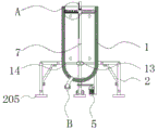
FIG. 1 is a schematic view of a front cross-sectional structure of a sewage treatment apparatus having a floating material collecting treatment according to the present invention;
FIG. 2 is a schematic side view showing a sewage treatment apparatus with flotage collection treatment according to the present invention;
FIG. 3 is a schematic rear view of a sewage treatment apparatus having a floating material collecting treatment according to the present invention;
FIG. 4 is an enlarged schematic view of a sewage treatment apparatus having a floating material collecting treatment according to the present invention at A in FIG. 1;
FIG. 5 is an enlarged view of the sewage treatment apparatus having a floating material collecting treatment according to the present invention at B of FIG. 1;
FIG. 6 is a schematic view of an enlarged top view of a collecting mechanism of a sewage treatment apparatus having a floating material collecting treatment according to the present invention.
In the figure: 1. an equipment housing; 2. a support mechanism; 201. a connecting rod; 202. a cylinder; 203. a support bar; 204. a connecting pin; 205. a brace; 3. a fixing plate; 4. a screw; 5. a first motor; 6. a chain; 7. a rotating shaft; 8. a sludge discharge mechanism; 801. a sealing cover; 802. a sludge discharge pipe; 9. a water level monitoring pipe; 10. a water inlet; 11. a valve; 12. a water outlet; 13. a wheel axle; 14. positioning a rod; 15. a positioning sleeve; 16. a second motor; 17. a gear; 18. a rack; 19. fixing the loop bar; 20. a third motor; 21. rotating the rod; 22. a fishing bucket; 23. a rotating wheel; 24. a collection mechanism; 2401. a collection box; 2402. hooking; 2403. hanging a ring; 25. a cleaning mechanism; 2501. cleaning the rod; 2502. and cleaning the brush.
Detailed Description
The technical solutions in the embodiments of the present invention will be clearly and completely described below with reference to the drawings in the embodiments of the present invention, and it is obvious that the described embodiments are only a part of the embodiments of the present invention, and not all of the embodiments.
In the description of the present invention, "a plurality" means two or more unless otherwise specified; the terms "upper", "lower", "left", "right", "inner", "outer", "front", "rear", "head", "tail", and the like, indicate orientations or positional relationships based on the orientations or positional relationships shown in the drawings, are only for convenience in describing and simplifying the description, and do not indicate or imply that the referred devices or elements must have a specific orientation, be constructed in a specific orientation, and be operated, and thus are not to be construed as limiting the present invention, and furthermore, the terms "first", "second", "third", and the like are only used for descriptive purposes and are not to be construed as indicating or implying relative importance.
In the description of the present invention, it is to be noted that, unless otherwise explicitly specified or limited, the terms "connected" and "connected" are to be interpreted broadly, e.g., as being fixed or detachable or integrally connected; can be mechanically or electrically connected; they may be directly connected or indirectly connected through an intermediate, and those skilled in the art will understand the specific meaning of the above terms in the present invention in specific situations.
Referring to fig. 1-6, the present invention provides a technical solution: a sewage treatment device with floater collecting and treating function comprises a device shell 1, a sludge discharging mechanism 8 and a positioning sleeve 15, wherein a supporting mechanism 2 is arranged outside the device shell 1, a fixing plate 3 is fixed below the device shell 1, the supporting mechanism 2 comprises a connecting rod 201, an air cylinder 202, a supporting rod 203, a connecting pin 204 and a supporting foot 205, the air cylinder 202 is connected below the connecting rod 201, the supporting rod 203 is arranged on the left side of the air cylinder 202, the connecting pin 204 is connected below the supporting rod 203, the supporting foot 205 is arranged below the connecting pin 204, the supporting rod 203 is connected with the supporting foot 205 through the connecting pin 204, the supporting rod 203 is movably connected with the connecting rod 201, the included angle between the connecting rod 201 and the supporting rod 203 is controlled through the air cylinder 202, so that the device shell 1 is lifted, a worker can collect sediments by a trolley conveniently, the height of the device shell 1 is reduced when the device normally works, the gravity center of the equipment is moved downwards, and the stability of the equipment is improved.
One side of fixed plate 3 is provided with screw 4, and first motor 5 is installed to the opposite side of screw 4, the top of first motor 5 is connected with chain 6, and one side of chain 6 is connected with pivot 7, pivot 7 is connected with first motor 5 through chain 6, and pivot 7 constitutes revolution mechanic through between shaft 13 and the equipment shell 1, it is rotatory to drive pivot 7 through chain 6 through first motor 5, thereby it is rotatory to drive to salvage and fight 22, salvage the floater on sewage surface, improve equipment's sewage treatment effect.
The mud discharging mechanism 8 is located on the other side of the rotating shaft 7, the mud discharging mechanism 8 comprises a sealing cover 801 and a mud discharging pipe 802, the mud discharging pipe 802 is arranged above the sealing cover 801, the sealing cover 801 is in threaded connection with the mud discharging pipe 802, a welding integrated structure is formed between the mud discharging pipe 802 and the equipment shell 1, a water level monitoring pipe 9 is installed behind the equipment shell 1, a water inlet 10 is formed in one side of the water level monitoring pipe 9, a conductor structure is formed between the water level monitoring pipe 9 and the equipment shell 1, the equipment shell 1 is bonded with the water level monitoring pipe 9, the water level inside the equipment is observed through the conductor structure formed between the water level monitoring pipe 9 and the equipment shell 1, then the gear 17 is controlled to rotate through a second motor 16, the gear 17 is matched with the rack 18 to control the height of the fixed loop bar 19, so that the fishing bucket 22 can be flush with the liquid level, and floating objects can be conveniently fished.
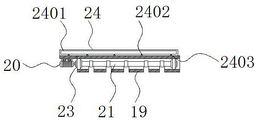
The positioning sleeve 15 is positioned above the wheel shaft 13, the second motor 16 is arranged above the positioning sleeve 15, a gear 17 is arranged on one side of the second motor 16, a rack 18 is fixed behind the gear 17, the outer surface of the gear 17 is meshed with the rack 18, the rack 18 is welded with the rotating shaft 7, fixed loop bars 19 are fixed on the left side and the right side of the positioning sleeve 15, a third motor 20 is arranged on one side, far away from the central axis of the rotating shaft 7, of the fixed loop bars 19, a rotating bar 21 is arranged inside the fixed loop bars 19, a fishing bucket 22 is fixed below the rotating bar 21, rotating wheels 23 are arranged at the left end and the right end of the rotating bar 21, a collecting mechanism 24 is arranged behind the fixed loop bars 19, the collecting mechanism 24 comprises a collecting box 2401, a hook 2402 and a hanging ring 2403, a hook 2402 is fixed above the collecting box 2401, a hanging ring 2403 is arranged in front of the hook 2402, the rotating bar 21 is controlled to rotate, thereby can control the rotation of fishing fill 22, be convenient for fishing fill 22 pour the floater of fishing into collecting box 2401, collecting box 2401 is articulated through couple 2402 and link 2403, is convenient for the staff to pull down collecting box 2401, clears up the floater.
To sum up, the sewage treatment device with floater collecting and treating function is characterized in that when in use, sewage is added into the device shell 1 through the water inlet 10, then the device is placed still to precipitate the sediments, the sediments float upwards, the liquid level in the device is observed through the water level monitoring pipe 9, then the second motor 16 is started to drive the gear 17 to rotate and the rack 18 to control the position of the fishing bucket 22, the fishing bucket 22 is convenient to fish the sediments, then the first motor 5 is started to drive the rotating shaft 7 to rotate through the chain 6, the shaft 7 is supported and positioned through the wheel shaft 13, the rotating shaft 7 rotates to drive the fixed sleeve rod 19 to rotate, the fishing bucket 22 is further driven to rotate to fish the sediments, meanwhile, the cleaning rod 2501 also rotates along with the rotating shaft 7, the cleaning brush 2502 is driven to clean the inner surface of the device shell 1, then the third motor 20 is started to control the rotating rod 23 to rotate 21 which forms a rotating structure with the fixed sleeve rod 19 through the rotating wheel 23, thereby it is rotatory to drive and to drag for the inside of pouring the floater of dragging for the fill 22 and pour collecting box 2401, collecting box 2401 is articulated through couple 2402 and link 2403, the inside sewage of depositing the completion of equipment is discharged through outlet 12 after the equipment work finishes, open cylinder 202, the contained angle between control bracing piece 203 and the connecting rod 201 to promote equipment shell 1, then open and the sealed lid 801 discharge apparatus inside precipitate of threaded connection between mud pipe 802.
The above description is only for the preferred embodiment of the present invention, but the scope of the present invention is not limited thereto, and any person skilled in the art should be considered to be within the technical scope of the present invention, and the technical solutions and the inventive concepts thereof according to the present invention should be equivalent or changed within the scope of the present invention.
Claims (10)
1. The utility model provides a sewage treatment device with floater collection handles, includes equipment shell (1), row's mud mechanism (8) and position sleeve (15), its characterized in that: the device comprises a device shell (1), a supporting mechanism (2) is arranged outside the device shell (1), a fixing plate (3) is fixed below the device shell (1), a screw (4) is arranged on one side of the fixing plate (3), a first motor (5) is installed on the other side of the screw (4), a chain (6) is connected above the first motor (5), a rotating shaft (7) is connected on one side of the chain (6), a sludge discharge mechanism (8) is located on the other side of the rotating shaft (7), a water level monitoring pipe (9) is installed behind the device shell (1), a water inlet (10) is arranged on one side of the water level monitoring pipe (9), a valve (11) is installed above the water inlet (10), a water outlet (12) is fixed below the water inlet (10), a wheel shaft (13) is arranged outside the rotating shaft (7), and a positioning rod (14) is connected outside the wheel shaft (13), the top of pivot (7) is provided with clearance mechanism (25), position sleeve (15) are located the top of shaft (13), and the top of position sleeve (15) installs second motor (16), one side of second motor (16) is provided with gear (17), and the rear of gear (17) is fixed with rack (18), the left and right sides of position sleeve (15) is fixed with fixed loop bar (19), and one side of keeping away from pivot (7) axis in fixed loop bar (19) installs third motor (20), the internally mounted of fixed loop bar (19) has dwang (21), and the below of dwang (21) is fixed with drags for and fights (22), both ends are provided with runner (23) about dwang (21), the rear of fixed loop bar (19) is provided with collection mechanism (24).
2. The sewage treatment apparatus having a floating material collecting process according to claim 1, wherein: the supporting mechanism (2) comprises a connecting rod (201), a cylinder (202), a supporting rod (203), a connecting pin (204) and a supporting foot (205), the cylinder (202) is connected to the lower portion of the connecting rod (201), the supporting rod (203) is arranged on the left side of the cylinder (202), the connecting pin (204) is connected to the lower portion of the supporting rod (203), and the supporting foot (205) is arranged below the connecting pin (204).
3. The sewage treatment apparatus having a floating material collecting process according to claim 2, wherein: the supporting rod (203) is connected with the supporting foot (205) through a connecting pin (204), and the supporting rod (203) is movably connected with the connecting rod (201).
4. The sewage treatment apparatus having a floating material collecting process according to claim 1, wherein: the rotating shaft (7) is connected with the first motor (5) through a chain (6), and the rotating shaft (7) forms a rotating structure with the equipment shell (1) through a wheel shaft (13).
5. The sewage treatment apparatus having a floating material collecting process according to claim 1, wherein: the sludge discharge mechanism (8) comprises a sealing cover (801) and a sludge discharge pipe (802), and the sludge discharge pipe (802) is arranged above the sealing cover (801).
6. The sewage treatment apparatus having a floating material collecting process according to claim 5, wherein: the sealing cover (801) is in threaded connection with the sludge discharge pipe (802), and the sludge discharge pipe (802) and the equipment shell (1) form a welding integrated structure.
7. The sewage treatment apparatus having a floating material collecting process according to claim 1, wherein: a conduction device structure is formed between the water level monitoring pipe (9) and the equipment shell (1), and the equipment shell (1) is bonded with the water level monitoring pipe (9).
8. The sewage treatment apparatus having a floating material collecting process according to claim 1, wherein: the outer surface of the gear (17) is meshed with the rack (18), and the rack (18) is welded with the rotating shaft (7).
9. The sewage treatment apparatus having a floating material collecting process according to claim 1, wherein: the collecting mechanism (24) comprises a collecting box (2401), a hook (2402) and a hanging ring (2403), the hook (2402) is fixed above the collecting box (2401), and the hanging ring (2403) is arranged in front of the hook (2402).
10. The sewage treatment apparatus having a floating material collecting process according to claim 1, wherein: clearance mechanism (25) are including clearance pole (2501) and clearance brush (2502), and one side that equipment shell (1) axis was kept away from in clearance pole (2501) is provided with clearance brush (2502).
Priority Applications (1)
| Application Number | Priority Date | Filing Date | Title |
|---|---|---|---|
| CN202010563446.0A CN111661945A (en) | 2020-06-19 | 2020-06-19 | Sewage treatment device with floater collecting and treating functions |
Applications Claiming Priority (1)
| Application Number | Priority Date | Filing Date | Title |
|---|---|---|---|
| CN202010563446.0A CN111661945A (en) | 2020-06-19 | 2020-06-19 | Sewage treatment device with floater collecting and treating functions |
Publications (1)
| Publication Number | Publication Date |
|---|---|
| CN111661945A true CN111661945A (en) | 2020-09-15 |
Family
ID=72388893
Family Applications (1)
| Application Number | Title | Priority Date | Filing Date |
|---|---|---|---|
| CN202010563446.0A Pending CN111661945A (en) | 2020-06-19 | 2020-06-19 | Sewage treatment device with floater collecting and treating functions |
Country Status (1)
| Country | Link |
|---|---|
| CN (1) | CN111661945A (en) |
Cited By (1)
| Publication number | Priority date | Publication date | Assignee | Title |
|---|---|---|---|---|
| CN112340868A (en) * | 2020-11-24 | 2021-02-09 | 贵州师范学院 | Industrial sewage treatment and purification equipment |
Citations (17)
| Publication number | Priority date | Publication date | Assignee | Title |
|---|---|---|---|---|
| CN101182053A (en) * | 2007-11-12 | 2008-05-21 | 中国海洋石油总公司 | Backflow air-floating device for water-arrangement optimization multi-phase flow pump |
| JP2011005435A (en) * | 2009-06-26 | 2011-01-13 | Sumiju Kankyo Engineering Kk | Scum scraping device and sedimentation tank |
| WO2011095674A1 (en) * | 2010-02-04 | 2011-08-11 | Finnketju Invest Oy | Apparatus for removal of surface scum |
| CN202007147U (en) * | 2011-02-25 | 2011-10-12 | 宝山钢铁股份有限公司 | Scum collector |
| CN103301658A (en) * | 2013-04-27 | 2013-09-18 | 江苏中超环保有限公司 | Efficient micro-resistance pulsating vortex sedimentation device |
| CN106621491A (en) * | 2017-01-12 | 2017-05-10 | 河海大学常州校区 | Suspended center-transmission sludge scraper |
| CN107520361A (en) * | 2017-10-20 | 2017-12-29 | 南京泓凯动力系统科技有限公司 | A kind of diel cylinder discharging structure for stamping parts of automobile |
| CN107697980A (en) * | 2017-11-29 | 2018-02-16 | 成都市世纪花园家庭农场 | A kind of sewage float fishing device |
| CN207361841U (en) * | 2017-09-01 | 2018-05-15 | 冯权识 | A kind of oil removing skimmer device for sewage treatment plant |
| CN108619763A (en) * | 2018-07-02 | 2018-10-09 | 江苏自强环保科技有限公司 | Mud-sucking device is scraped in a kind of rotation of periphery |
| CN109368964A (en) * | 2018-11-29 | 2019-02-22 | 杭州渗源环境科技有限公司 | A kind of mud conditioning device |
| CN208911522U (en) * | 2018-08-24 | 2019-05-31 | 嘉兴市金乐染织有限公司 | A kind of secondary settling tank |
| CN110255779A (en) * | 2019-07-23 | 2019-09-20 | 东莞理工学院 | A kind of intelligent industrial sewage treatment mechanism of qi device |
| CN209900778U (en) * | 2019-03-20 | 2020-01-07 | 北京远浪潮生态建设有限公司 | Floater processing apparatus for sewage treatment |
| CN210313636U (en) * | 2019-07-08 | 2020-04-14 | 福建省钜港环保科技有限公司 | Oil-removing and slag-removing device for sewage treatment |
| CN210528528U (en) * | 2019-07-05 | 2020-05-15 | 绍兴市高砚智生物科技有限公司 | Sewage treatment pond mud scum collection device |
| CN210728769U (en) * | 2019-07-16 | 2020-06-12 | 重庆金瑞图环保科技有限公司 | Scum collecting device |
-
2020
- 2020-06-19 CN CN202010563446.0A patent/CN111661945A/en active Pending
Patent Citations (17)
| Publication number | Priority date | Publication date | Assignee | Title |
|---|---|---|---|---|
| CN101182053A (en) * | 2007-11-12 | 2008-05-21 | 中国海洋石油总公司 | Backflow air-floating device for water-arrangement optimization multi-phase flow pump |
| JP2011005435A (en) * | 2009-06-26 | 2011-01-13 | Sumiju Kankyo Engineering Kk | Scum scraping device and sedimentation tank |
| WO2011095674A1 (en) * | 2010-02-04 | 2011-08-11 | Finnketju Invest Oy | Apparatus for removal of surface scum |
| CN202007147U (en) * | 2011-02-25 | 2011-10-12 | 宝山钢铁股份有限公司 | Scum collector |
| CN103301658A (en) * | 2013-04-27 | 2013-09-18 | 江苏中超环保有限公司 | Efficient micro-resistance pulsating vortex sedimentation device |
| CN106621491A (en) * | 2017-01-12 | 2017-05-10 | 河海大学常州校区 | Suspended center-transmission sludge scraper |
| CN207361841U (en) * | 2017-09-01 | 2018-05-15 | 冯权识 | A kind of oil removing skimmer device for sewage treatment plant |
| CN107520361A (en) * | 2017-10-20 | 2017-12-29 | 南京泓凯动力系统科技有限公司 | A kind of diel cylinder discharging structure for stamping parts of automobile |
| CN107697980A (en) * | 2017-11-29 | 2018-02-16 | 成都市世纪花园家庭农场 | A kind of sewage float fishing device |
| CN108619763A (en) * | 2018-07-02 | 2018-10-09 | 江苏自强环保科技有限公司 | Mud-sucking device is scraped in a kind of rotation of periphery |
| CN208911522U (en) * | 2018-08-24 | 2019-05-31 | 嘉兴市金乐染织有限公司 | A kind of secondary settling tank |
| CN109368964A (en) * | 2018-11-29 | 2019-02-22 | 杭州渗源环境科技有限公司 | A kind of mud conditioning device |
| CN209900778U (en) * | 2019-03-20 | 2020-01-07 | 北京远浪潮生态建设有限公司 | Floater processing apparatus for sewage treatment |
| CN210528528U (en) * | 2019-07-05 | 2020-05-15 | 绍兴市高砚智生物科技有限公司 | Sewage treatment pond mud scum collection device |
| CN210313636U (en) * | 2019-07-08 | 2020-04-14 | 福建省钜港环保科技有限公司 | Oil-removing and slag-removing device for sewage treatment |
| CN210728769U (en) * | 2019-07-16 | 2020-06-12 | 重庆金瑞图环保科技有限公司 | Scum collecting device |
| CN110255779A (en) * | 2019-07-23 | 2019-09-20 | 东莞理工学院 | A kind of intelligent industrial sewage treatment mechanism of qi device |
Non-Patent Citations (1)
| Title |
|---|
| D.R.伍德利等: "《物料搬运》", 30 June 1975, 机械工业出版社 * |
Cited By (1)
| Publication number | Priority date | Publication date | Assignee | Title |
|---|---|---|---|---|
| CN112340868A (en) * | 2020-11-24 | 2021-02-09 | 贵州师范学院 | Industrial sewage treatment and purification equipment |
Similar Documents
| Publication | Publication Date | Title |
|---|---|---|
| CN207144001U (en) | A kind of inspection shaft easy to clean | |
| CN109853502B (en) | Water surface garbage transverse interception fishing device for hydraulic engineering | |
| CN111661945A (en) | Sewage treatment device with floater collecting and treating functions | |
| CN111794199A (en) | Automatic fishing device of surface of water rubbish for hydraulic engineering | |
| CN211646673U (en) | Municipal administration road drainage structure | |
| CN211773484U (en) | Tower type water conservancy trash remover | |
| CN112090893A (en) | Underwater cleaning robot | |
| CN211172339U (en) | Integrated sewage treatment pump station | |
| CN209575861U (en) | A kind for the treatment of tank mud scum slag collection side removal device | |
| CN218011319U (en) | Mechanical chemical industry equipment circulating water equipment | |
| CN110841523A (en) | Multifunctional loam matrix spray-seeding equipment for mine restoration | |
| CN216584304U (en) | Sewage suspended solid fishing device | |
| CN212957842U (en) | Underwater dirt suction device for swimming pool | |
| CN214829408U (en) | Oil-water filtering device in sewage | |
| CN210495402U (en) | Sewage filtering device | |
| CN209924012U (en) | Park is silt cleaning device for lake | |
| CN112221234A (en) | Mining is sewage treatment plant for scene | |
| CN214344618U (en) | Small-size sewage treatment boat form sedimentation tank device | |
| CN214130433U (en) | Sand setting device for sewage treatment | |
| CN220847759U (en) | Water conservancy desilting mechanism | |
| CN213221104U (en) | Sewage treatment device for livestock farm | |
| CN216574821U (en) | Water treatment equipment for solid waste | |
| CN212926225U (en) | Efficient water conservancy construction sediment removal device | |
| CN213885250U (en) | Sewage treatment filter equipment | |
| CN215901034U (en) | Waste water treatment desilting device for hydraulic engineering |
Legal Events
| Date | Code | Title | Description |
|---|---|---|---|
| PB01 | Publication | ||
| PB01 | Publication | ||
| SE01 | Entry into force of request for substantive examination | ||
| SE01 | Entry into force of request for substantive examination | ||
| RJ01 | Rejection of invention patent application after publication | ||
| RJ01 | Rejection of invention patent application after publication |
Application publication date: 20200915 |