CN111545813A - Machining process for cross cutter groove of front disc part of reaming machine winch - Google Patents
Machining process for cross cutter groove of front disc part of reaming machine winch Download PDFInfo
- Publication number
- CN111545813A CN111545813A CN202010495583.5A CN202010495583A CN111545813A CN 111545813 A CN111545813 A CN 111545813A CN 202010495583 A CN202010495583 A CN 202010495583A CN 111545813 A CN111545813 A CN 111545813A
- Authority
- CN
- China
- Prior art keywords
- positioning
- front disc
- disc part
- plate
- milling
- Prior art date
- Legal status (The legal status is an assumption and is not a legal conclusion. Google has not performed a legal analysis and makes no representation as to the accuracy of the status listed.)
- Granted
Links
Images


Classifications
-
- B—PERFORMING OPERATIONS; TRANSPORTING
- B23—MACHINE TOOLS; METAL-WORKING NOT OTHERWISE PROVIDED FOR
- B23C—MILLING
- B23C3/00—Milling particular work; Special milling operations; Machines therefor
- B23C3/28—Grooving workpieces
-
- B—PERFORMING OPERATIONS; TRANSPORTING
- B23—MACHINE TOOLS; METAL-WORKING NOT OTHERWISE PROVIDED FOR
- B23C—MILLING
- B23C9/00—Details or accessories so far as specially adapted to milling machines or cutter
-
- B—PERFORMING OPERATIONS; TRANSPORTING
- B23—MACHINE TOOLS; METAL-WORKING NOT OTHERWISE PROVIDED FOR
- B23Q—DETAILS, COMPONENTS, OR ACCESSORIES FOR MACHINE TOOLS, e.g. ARRANGEMENTS FOR COPYING OR CONTROLLING; MACHINE TOOLS IN GENERAL CHARACTERISED BY THE CONSTRUCTION OF PARTICULAR DETAILS OR COMPONENTS; COMBINATIONS OR ASSOCIATIONS OF METAL-WORKING MACHINES, NOT DIRECTED TO A PARTICULAR RESULT
- B23Q1/00—Members which are comprised in the general build-up of a form of machine, particularly relatively large fixed members
- B23Q1/25—Movable or adjustable work or tool supports
-
- B—PERFORMING OPERATIONS; TRANSPORTING
- B23—MACHINE TOOLS; METAL-WORKING NOT OTHERWISE PROVIDED FOR
- B23Q—DETAILS, COMPONENTS, OR ACCESSORIES FOR MACHINE TOOLS, e.g. ARRANGEMENTS FOR COPYING OR CONTROLLING; MACHINE TOOLS IN GENERAL CHARACTERISED BY THE CONSTRUCTION OF PARTICULAR DETAILS OR COMPONENTS; COMBINATIONS OR ASSOCIATIONS OF METAL-WORKING MACHINES, NOT DIRECTED TO A PARTICULAR RESULT
- B23Q3/00—Devices holding, supporting, or positioning work or tools, of a kind normally removable from the machine
- B23Q3/02—Devices holding, supporting, or positioning work or tools, of a kind normally removable from the machine for mounting on a work-table, tool-slide, or analogous part
- B23Q3/06—Work-clamping means
- B23Q3/062—Work-clamping means adapted for holding workpieces having a special form or being made from a special material
-
- B—PERFORMING OPERATIONS; TRANSPORTING
- B23—MACHINE TOOLS; METAL-WORKING NOT OTHERWISE PROVIDED FOR
- B23Q—DETAILS, COMPONENTS, OR ACCESSORIES FOR MACHINE TOOLS, e.g. ARRANGEMENTS FOR COPYING OR CONTROLLING; MACHINE TOOLS IN GENERAL CHARACTERISED BY THE CONSTRUCTION OF PARTICULAR DETAILS OR COMPONENTS; COMBINATIONS OR ASSOCIATIONS OF METAL-WORKING MACHINES, NOT DIRECTED TO A PARTICULAR RESULT
- B23Q5/00—Driving or feeding mechanisms; Control arrangements therefor
- B23Q5/22—Feeding members carrying tools or work
Abstract
The invention relates to a machining process of a cross cutter groove of a front disc part of a hinge plate of a threading machine, wherein a rotary worktable is arranged on a machine tool bedplate, a clamp is arranged on the rotary worktable, four positioning shafts B are arranged on the clamp, a corresponding front disc part is arranged on each positioning shaft B, a zero scale mark of the rotary worktable is consistent with the longitudinal direction of the machine tool bedplate when machining is carried out, and when machining is carried out, every 90-degree rotation is carried out for milling along the longitudinal direction of the machine tool bedplate, all cutter grooves can be machined only by rotating 90 degrees for four times. The invention achieves the following beneficial effects: low cost, high processing efficiency, high processing precision and easy realization.
Description
Technical Field
The invention relates to the technical field of machining of a front disc of a pipe cutting and threading machine, in particular to a machining process of a cross cutter groove of a front disc part of a hinge plate of a threading machine.
Background
The front disc is a key part of a key part hinge plate of a pipe cutting and threading machine, influences the stability and high quality of threading operation and is a common nodular iron casting. On the front disc, four knife grooves (threading die moving grooves or cross knife grooves) are designed to be filled with four threading dies and move, so that the precision of the knife grooves is a key structure influencing the installation of the front disc. However, the milling of the four cutter grooves of the front disc is one of the difficulties in the processing of the part, which not only has high technical requirements on machine tool operators, but also has difficulty in clamping, calibrating and aligning.
The existing processing method of the cross cutter groove is to process by using a disc milling cutter on a common horizontal milling machine, and design a special milling clamp into an indexing rotary milling clamp for single-piece processing. And after the first groove is milled, the positioning pin is taken out, the transition plate is rotated to the 90-degree indexing position, and then the positioning pin is inserted to mill the second groove. In the milling process, the clamping time is long, the centering size and alignment are difficult, and the problems that the size precision of the groove width, the groove depth, the center indexing of four cutter grooves, the centering degree of the groove width relative to the center line of the groove width and the like are poor, and the size consistency of different parts is poor exist; the cantilever type machining is adopted on a common horizontal milling machine, and due to the limitation of the specification and the model of the machine tool, the adopted cutter bar is thin, the strength and the rigidity are insufficient, the labor intensity is high, the machining efficiency is reduced, the machining time is long, the whole production rhythm of batch production cannot be met, and the bottleneck of production is formed. However, if a numerical control machine tool is adopted, the numerical control machine tool is very expensive and very high in cost.
Disclosure of Invention
The invention aims to overcome the defects of the prior art and provides a machining process of a cross cutter groove of a front disc part of a reaming machine winch, which has the advantages of low cost, high machining efficiency, high machining precision and easiness in realization.
The purpose of the invention is realized by the following technical scheme: a kind of mantle fiber machine hinge plate part cross cutter groove machining process, the processing step is:
s1, arranging a rotary workbench on the bedplate of the machine tool, and aligning by marking a meter to ensure the position precision and ensure that the 0-degree scale mark of the rotary workbench is parallel to the longitudinal movement direction of the bedplate of the machine tool;
s2, arranging a clamp at the center of the rotary workbench, wherein the clamp comprises a positioning plate, the positioning plate is arranged at the center of the rotary workbench through a positioning shaft A, four positioning shafts B are arranged along the circumferential direction of the positioning shaft A, the upper end of each positioning shaft B is provided with an installation head for installing a front disc part, and the positioning plate is also provided with a positioning pin for positioning the front disc part and a pressing plate for pressing the front disc part;
s3, mounting, namely mounting the front disc part on a mounting head of a positioning shaft B, positioning the front disc part on a positioning plate through a positioning pin, and fixing the front disc part through a pressing plate, wherein the front disc part is named as a front disc part A, a front disc part B, a front disc part C and a front disc part D respectively and corresponds to one positioning shaft B respectively;
s4, milling;
s41, starting the machine tool, operating the machine tool to enable the machine tool platen under the table top to move longitudinally, and milling the cutter grooves on the front disc part A and the front disc part B along the longitudinal axis;
s42, operating the machine tool platen to withdraw the milling cutter to a starting position, rotating the rotary workbench by 90 degrees, and milling the cutter grooves on the front disc part D and the front disc part A along the transverse axis;
s43, operating the machine tool platen to withdraw the milling cutter to the starting position, rotating the rotary workbench by 90 degrees, and milling the cutter grooves on the front disc part C and the front disc part D along the longitudinal axis;
s44, operating the machine tool platen to withdraw the milling cutter to the starting position, rotating the rotary workbench by 90 degrees, and milling the cutter grooves on the front disc part B and the front disc part C along the transverse axis;
s5, loosening the positioning pin and the pressing plate, and taking down the four processed front disc parts;
s6, resetting the rotary workbench, and repeating the steps S3, S4 and S5.
Further, in step S4, before the formal milling, trial machining adjustment is required, that is, the transverse position of the disc milling cutter is adjusted by the movement of the machine tool spindle, and trial machining is performed by centering and aligning the central dimension of the part of the front disc to be machined and the position of the cross-shaped tool groove; then, the parts are detected, and the machining parameters are adjusted.
Furthermore, in the four positioning shafts B, adjacent positioning shafts B are symmetrical back and forth or left and right, and nonadjacent positioning shafts B are symmetrical along the positioning shaft A.
Furthermore, the upper surface of swivel work head open and to have T type groove, the locating plate lower surface of anchor clamps is opened and is had U type groove, realizes fixing of anchor clamps direction of rotation through placing the key in T type groove and U type groove.
Preferably, the positioning shaft A and the positioning shaft B are stepped shafts.
Preferably, the rotary worktable and the positioning plate are both provided with positioning holes A matched with the positioning shaft A, and the matching of the two positioning holes A and the positioning shaft A adopts H7/H6.
Preferably, the positioning plate is provided with a positioning hole B corresponding to the positioning pin, the upper deviation of the positioning hole B is +0.018, and the lower deviation is 0.
Furthermore, a backing plate is circumferentially fixed on the positioning shaft B on the positioning plate, and the backing plate is used for lining a front plate part which is arranged on the positioning plate and positioned by the mounting head.
Furthermore, the pressing plate is of an open hook type and is fixed on the positioning plate through a compression nut.
Furthermore, the positioning plate is provided with positioning pin holes and base plate mounting bolt holes corresponding to different front disc part models.
The invention has the following advantages:
(1) compared with the traditional method that only one front disc part is installed, and the positioning pin, the transition plate on the rotary tool and the fixed positioning pin need to be disassembled again after each cutter groove in a certain direction is machined, the clamp and the rotary workbench are structurally arranged, so that four front disc parts can be machined at one time after one-time installation, and the cross cutter grooves of the four front disc parts only need to rotate the rotary workbench for four times for milling, so that repeated disassembly of the front disc parts is avoided, the installation error is reduced, the machining efficiency is improved, and the machining size precision is improved in multiples;
(2) the rotary workbench and the clamp in the scheme have simple structures, are convenient to design and manufacture, and are beneficial to reducing the equipment cost of a factory;
(3) the structural design of the positioning pin, the pressing plate and the T-shaped groove and the U-shaped groove ensures the installation precision.
Drawings
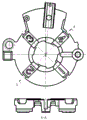
FIG. 1 is a top view of a front disk part;
FIG. 2 is a bottom view of the front disk part;
FIG. 3 is a schematic view of the structure of the fixture of the present invention mounted on a rotary table;
FIG. 4 is a schematic view of the structure of the front plate part mounted on the fixture;
FIG. 5 is a structural view of a platen;
in the figure: in the figure: 1-rotary workbench, 2-clamp, 201-positioning plate, 202-positioning shafts A and 203-positioning shafts B, 3-front disc part, 4-positioning pin, 5-pressing plate and 6-backing plate.
Detailed Description
The invention will be further described with reference to the accompanying drawings, but the scope of the invention is not limited to the following.
As shown in fig. 1 to 5, a machining process of a cross cutter groove of a front disc part of a reaming plate of a threading machine is based on a rotary worktable 1, a clamp 2 and a precise horizontal milling machine with the characteristics of high power, large cutter handle and thick cutter bar.
Specifically, a rotary workbench 1 is arranged on a bedplate of the machine tool, the position precision is ensured by the calibration of a meter, and the 0-degree scale mark of the rotary workbench 1 is ensured to be parallel to the longitudinal movement direction of the bedplate of the machine tool; a jig 2 is installed and provided at the center of the rotary table 1 through a positioning shaft a202, and a plurality of front disc parts 3 are installed on the jig 2. In the embodiment, the BT50 cutter handle and the cutter rod with the diameter of 80mm are preferably selected by the precision horizontal milling machine.
The fixture 2, as shown in fig. 3, includes a positioning plate 201, the positioning plate 201 is disposed at the center of the rotary table 1 through a positioning shaft a202, four positioning shafts B203 are disposed along the circumference of the positioning shaft a202, the upper end of the positioning shafts B203 is a mounting head for mounting the front disc part, and the positioning plate 201 is further provided with a positioning pin 4 for positioning the front disc part 3 and a pressing plate 5 for pressing the front disc part.
The method comprises the following steps: of the four positioning axes B203, adjacent positioning axes B203 are symmetrical in the front-back or left-right direction, and nonadjacent positioning axes B203 are symmetrical in the positioning axis a 202.
In FIG. 2, the cross-shaped tool slot to be processed is formed at the J-J section.
When the scheme is processed, the processing technology comprises the following steps:
s1, arranging a rotary workbench 1 on a bedplate of the machine tool, and aligning by marking a meter to ensure the position precision and ensure that the 0-degree scale mark of the rotary workbench 1 is parallel to the longitudinal movement direction of the bedplate of the machine tool;
s2, arranging a clamp 2 at the center of the rotary workbench 1, wherein the rotary workbench 1 and the positioning plate 201 are both provided with positioning holes A matched with the positioning shafts A202, and the matching of the two positioning holes A and the positioning shafts A202 adopts H7/H6; moreover, a T-shaped groove is formed in the upper surface of the rotary workbench 1, a U-shaped groove is formed in the lower surface of the positioning plate 201 of the clamp 2, and the fixing of the clamp 2 in the rotating direction is realized by placing keys in the T-shaped groove and the U-shaped groove;
s3, mounting, namely mounting the front disc part 3 on a mounting head of a positioning shaft B203, positioning the front disc part 3 on the positioning plate 201 through the positioning pin 4, fixing the front disc part 3 through the pressing plate 5, and respectively naming the front disc part 3 as a front disc part A, a front disc part B, a front disc part C and a front disc part D and respectively corresponding to one positioning shaft B203; wherein, a positioning hole B corresponding to the positioning pin 4 is arranged on the positioning plate 201, the upper deviation of the positioning hole B is +0.018, and the lower deviation is 0;
s4, milling;
s41, starting the machine tool, operating the machine tool to enable the machine tool platen under the table top to move longitudinally, and milling the cutter grooves on the front disc part A and the front disc part B along the longitudinal axis;
s42, operating the machine tool platen to withdraw the milling cutter to a starting position, rotating the rotary workbench 1 by 90 degrees, and milling the cutter grooves on the front disc part D and the front disc part A along the transverse axis;
s43, operating the machine tool platen to withdraw the milling cutter to the starting position, rotating the rotary workbench 1 by 90 degrees, and milling the cutter grooves on the front disc part C and the front disc part D along the longitudinal axis;
s44, operating the machine tool platen to withdraw the milling cutter to the starting position, rotating the rotary workbench 1 by 90 degrees, and milling the cutter grooves on the front disc part B and the front disc part C along the transverse axis;
s5, loosening the positioning pin 4 and the pressing plate 5, and taking down the four machined front disc parts;
s6, resetting the rotary table 1, and repeating the steps S3, S4 and S5.
Before formal milling in step S4, trial machining adjustment is required, that is, the transverse position of the disc milling cutter is adjusted through movement of the machine tool spindle, and trial machining is performed by centering and aligning the central dimension of the part to be machined of the front disc part 3 and the position of the cross tool slot; then, the parts are detected, and the machining parameters are adjusted.
Preferably, the positioning axis a202 and the positioning axis B203 are stepped axes.
In this embodiment, the positioning shaft B203 of the positioning plate 201 has a cushion plate 6 fixed to the circumference thereof, and the cushion plate 6 is fastened to the positioning plate 201 by a countersunk bolt to cushion the front disc part 3 mounted on the positioning plate 201 and positioned by the mounting head. The backing plate 6 combines the positioning pin 4 and the pressing plate 5 to realize firm and accurate positioning of the front disc part 3.
As shown in fig. 5, the pressing plate 5 is of an open hook type: the hook-shaped parts at the upper part are two parallel hook-shaped structures which are beneficial to being contacted with the front disc part 3 at multiple points and pressed downwards; the lower part is a horizontal plate, a waist-shaped hole is arranged on the horizontal plate, and the pressing plate 6 is fixed on the positioning plate 201 through a compression nut arranged at the waist-shaped hole.
In this scheme, in order to adapt to the front plate part 3 of different models, be provided with different series's location pinhole, backing plate mounting bolt hole on locating plate 201, location round pin hole installs locating pin 4 correspondingly, and backing plate mounting bolt hole installs the backing plate correspondingly.
The foregoing is merely a preferred embodiment of the invention, it is to be understood that the invention is not limited to the forms disclosed herein, but is not intended to be exhaustive or to limit the invention to other embodiments, and to various other combinations, modifications, and environments and may be modified within the scope of the inventive concept as described herein by the teachings or the skill or knowledge of the relevant art. And that modifications and variations may be effected by those skilled in the art without departing from the spirit and scope of the invention as defined by the appended claims.
Claims (10)
1. A kind of mantle fiber machine capstan front plate part cross cutter slot machine processing craft, characterized by that:
the processing steps are as follows:
s1, arranging a rotary workbench (1) on a bedplate of the machine tool, and aligning by marking a meter to ensure the position precision and ensure that the 0-degree scale mark of the rotary workbench (1) is parallel to the longitudinal movement direction of the bedplate of the machine tool;
s2, arranging a clamp (2) at the center of a rotary workbench (1), wherein the clamp (2) comprises a positioning plate (201), the positioning plate (201) is arranged at the center of the rotary workbench (1) through a positioning shaft A (202), four positioning shafts B (203) are arranged along the circumferential direction of the positioning shaft A (202), the upper end of each positioning shaft B (203) is provided with an installation head for installing a front disc part, and the positioning plate (201) is also provided with a positioning pin (4) for positioning the front disc part (3) and a pressing plate (5) for pressing the front disc part;
s3, mounting, namely mounting the front disc part (3) on a mounting head of a positioning shaft B (203), positioning the front disc part (3) on a positioning plate (201) through a positioning pin (4), fixing the front disc part (3) through a pressing plate (5), wherein the front disc part (3) is named as a front disc part A, a front disc part B, a front disc part C and a front disc part D respectively and corresponds to one positioning shaft B (203);
s4, milling;
s41, starting the machine tool, operating the machine tool to enable the machine tool platen under the table top to move longitudinally, and milling the cutter grooves on the front disc part A and the front disc part B along the longitudinal axis;
s42, operating the machine tool platen to withdraw the milling cutter to a starting position, rotating the rotary workbench (1) by 90 degrees, and milling the cutter grooves on the front disc part D and the front disc part A along the transverse axis;
s43, operating the machine tool platen to withdraw the milling cutter to the starting position, rotating the rotary workbench (1) by 90 degrees, and milling the cutter grooves on the front disc part C and the front disc part D along the longitudinal axis;
s44, operating the machine tool platen to withdraw the milling cutter to the starting position, rotating the rotary workbench (1) by 90 degrees, and milling the cutter grooves on the front disc part B and the front disc part C along the transverse axis;
s5, loosening the positioning pin (4) and the pressing plate (5), and taking down the four processed front disc parts (3);
s6, resetting the rotary table (1), and repeating the steps S3, S4 and S5.
2. The machining process of the cross cutter groove of the front disc part of the reaming machine hinge plate according to claim 1, characterized in that: in the step S4, before formal milling, trial machining adjustment is required, that is, the transverse position of the disc milling cutter is adjusted through movement of the machine tool spindle, and trial machining is performed by centering and aligning the central dimension of the part to be machined of the front disc part (3) and the position of the cross tool slot; then, the parts are detected, and the machining parameters are adjusted.
3. The machining process of the cross cutter groove of the front disc part of the reaming machine hinge plate according to claim 2, characterized in that: in the four positioning shafts B (203), adjacent positioning shafts B (203) are symmetrical back and forth or left and right, and nonadjacent positioning shafts B (203) are symmetrical along a positioning shaft A (202).
4. The machining process of the cross cutter groove of the front disc part of the reaming machine hinge plate according to claim 3, characterized in that: the upper surface of swivel work head (1) open and to have T type groove, locating plate (201) lower surface of anchor clamps (2) is opened and is had U type groove, realizes anchor clamps (2) direction of rotation's fixed through placing the key in T type groove and U type groove.
5. The machining process of the cross cutter groove of the front disc part of the reaming machine hinge plate according to claim 4, characterized in that: the positioning shaft A (202) and the positioning shaft B (203) are stepped shafts.
6. The machining process of the cross cutter groove of the front disc part of the reaming machine hinge plate according to claim 5, characterized in that: the rotary worktable (1) and the positioning plate (201) are respectively provided with a positioning hole A matched with the positioning shaft A (202), and the two positioning holes A are matched with the positioning shaft A (202) by H7/H6.
7. The machining process of the cross cutter groove of the front disc part of the reaming machine hinge plate according to claim 6, characterized in that: the positioning plate (201) is provided with a positioning hole B corresponding to the positioning pin (4), the upper deviation of the positioning hole B is +0.018, and the lower deviation of the positioning hole B is 0.
8. The machining process of the cross cutter groove of the front disc part of the reaming machine hinge plate according to claim 7, characterized in that: the positioning plate (201) is provided with a positioning shaft B (203) which is circumferentially fixed with a backing plate (6), and the backing plate (6) is used for lining a front plate part (3) which is arranged on the positioning plate (201) and positioned by a mounting head.
9. The machining process of the cross cutter groove of the front disc part of the reaming machine hinge plate according to claim 8, characterized in that: the pressing plate (5) is in an open hook shape and is fixed on the positioning plate (201) through a compression nut.
10. The machining process of the cross cutter groove of the front disc part of the reaming machine hinge plate according to any one of claims 1 to 9, characterized by comprising the following steps of: the positioning plate (201) is provided with positioning pin holes and base plate mounting bolt holes corresponding to different front disc part models.
Priority Applications (1)
| Application Number | Priority Date | Filing Date | Title |
|---|---|---|---|
| CN202010495583.5A CN111545813B (en) | 2020-06-03 | 2020-06-03 | Machining process of cross cutter groove of front disc part of reaming machine winch |
Applications Claiming Priority (1)
| Application Number | Priority Date | Filing Date | Title |
|---|---|---|---|
| CN202010495583.5A CN111545813B (en) | 2020-06-03 | 2020-06-03 | Machining process of cross cutter groove of front disc part of reaming machine winch |
Publications (2)
| Publication Number | Publication Date |
|---|---|
| CN111545813A true CN111545813A (en) | 2020-08-18 |
| CN111545813B CN111545813B (en) | 2022-10-28 |
Family
ID=71999318
Family Applications (1)
| Application Number | Title | Priority Date | Filing Date |
|---|---|---|---|
| CN202010495583.5A Active CN111545813B (en) | 2020-06-03 | 2020-06-03 | Machining process of cross cutter groove of front disc part of reaming machine winch |
Country Status (1)
| Country | Link |
|---|---|
| CN (1) | CN111545813B (en) |
Citations (19)
| Publication number | Priority date | Publication date | Assignee | Title |
|---|---|---|---|---|
| CN200988137Y (en) * | 2006-09-28 | 2007-12-12 | 柳绍平 | Automatic assembling device for cross key blank |
| CN102000982A (en) * | 2010-12-21 | 2011-04-06 | 重庆江利圣特机械制造有限责任公司 | Combined machine tool for processing screw holes |
| CN102019456A (en) * | 2009-09-15 | 2011-04-20 | 郑有太 | Universal joint oil groove milling machine of machine tool |
| CN102189425A (en) * | 2011-03-22 | 2011-09-21 | 南车戚墅堰机车有限公司 | Universal joint pin machining fixture |
| US20130192059A1 (en) * | 2012-01-30 | 2013-08-01 | Heinrich Steger | Machining apparatus for grinding, milling, polishing or the like of a dental workpiece |
| CN203665167U (en) * | 2014-01-23 | 2014-06-25 | 十堰鼎业工贸有限公司 | Horizontal milling machine pneumatic fixture device for cutting cross shaft oil grooves |
| CN203863344U (en) * | 2014-05-29 | 2014-10-08 | 四川工程职业技术学院 | Connecting rod bolt hole and step face finishing machine |
| CN104148834A (en) * | 2014-08-01 | 2014-11-19 | 广州市明森机电设备有限公司 | Equipment and method for efficiently welding chips of double-interface intelligent cards |
| CN104354026A (en) * | 2014-10-28 | 2015-02-18 | 安费诺(常州)电子有限公司 | Indexing fixture of horizontal milling machine for processing cross groove of water pump impeller |
| CN104400473A (en) * | 2014-10-17 | 2015-03-11 | 汤顺 | Special fixture for processing cross groove |
| CN104668961A (en) * | 2015-01-16 | 2015-06-03 | 刘磊 | Turning and milling composite machine and operation method |
| CN204771699U (en) * | 2015-06-24 | 2015-11-18 | 南京梅山冶金发展有限公司 | Adaptation is in fan -shaped breach milling fixture of vertical milling machine's disc part |
| CN205600528U (en) * | 2016-04-27 | 2016-09-28 | 平罗县华隆炭素有限公司 | Difunctional decline angular milling dish of whetting a knife |
| US20170028524A1 (en) * | 2015-07-31 | 2017-02-02 | Satisloh Ag | Method for Machining Optical Workpieces, In Particular, Plastic Spectacle Lenses |
| CN107649711A (en) * | 2017-09-18 | 2018-02-02 | 嘉善翱鹰五金制品厂 | A kind of cross of bolt twists the processing unit (plant) and processing method of groove |
| CN110524019A (en) * | 2019-07-31 | 2019-12-03 | 重庆机电职业技术学院 | A kind of new-type numerical control drilling machine of multistation for processing Model For The Bush-axle Type Parts radial hole |
| CN110560765A (en) * | 2019-09-27 | 2019-12-13 | 洛阳恒诺锚固技术有限公司 | efficient milling method for alloy groove of cross-shaped alloy drill bit |
| CN209792701U (en) * | 2018-11-13 | 2019-12-17 | 南通利联机床制造有限公司 | Double-station special machine tool |
| CN209830925U (en) * | 2019-01-03 | 2019-12-24 | 天润智能科技(昆山)有限公司 | Adjustable clamp with protection mechanism |
-
2020
- 2020-06-03 CN CN202010495583.5A patent/CN111545813B/en active Active
Patent Citations (19)
| Publication number | Priority date | Publication date | Assignee | Title |
|---|---|---|---|---|
| CN200988137Y (en) * | 2006-09-28 | 2007-12-12 | 柳绍平 | Automatic assembling device for cross key blank |
| CN102019456A (en) * | 2009-09-15 | 2011-04-20 | 郑有太 | Universal joint oil groove milling machine of machine tool |
| CN102000982A (en) * | 2010-12-21 | 2011-04-06 | 重庆江利圣特机械制造有限责任公司 | Combined machine tool for processing screw holes |
| CN102189425A (en) * | 2011-03-22 | 2011-09-21 | 南车戚墅堰机车有限公司 | Universal joint pin machining fixture |
| US20130192059A1 (en) * | 2012-01-30 | 2013-08-01 | Heinrich Steger | Machining apparatus for grinding, milling, polishing or the like of a dental workpiece |
| CN203665167U (en) * | 2014-01-23 | 2014-06-25 | 十堰鼎业工贸有限公司 | Horizontal milling machine pneumatic fixture device for cutting cross shaft oil grooves |
| CN203863344U (en) * | 2014-05-29 | 2014-10-08 | 四川工程职业技术学院 | Connecting rod bolt hole and step face finishing machine |
| CN104148834A (en) * | 2014-08-01 | 2014-11-19 | 广州市明森机电设备有限公司 | Equipment and method for efficiently welding chips of double-interface intelligent cards |
| CN104400473A (en) * | 2014-10-17 | 2015-03-11 | 汤顺 | Special fixture for processing cross groove |
| CN104354026A (en) * | 2014-10-28 | 2015-02-18 | 安费诺(常州)电子有限公司 | Indexing fixture of horizontal milling machine for processing cross groove of water pump impeller |
| CN104668961A (en) * | 2015-01-16 | 2015-06-03 | 刘磊 | Turning and milling composite machine and operation method |
| CN204771699U (en) * | 2015-06-24 | 2015-11-18 | 南京梅山冶金发展有限公司 | Adaptation is in fan -shaped breach milling fixture of vertical milling machine's disc part |
| US20170028524A1 (en) * | 2015-07-31 | 2017-02-02 | Satisloh Ag | Method for Machining Optical Workpieces, In Particular, Plastic Spectacle Lenses |
| CN205600528U (en) * | 2016-04-27 | 2016-09-28 | 平罗县华隆炭素有限公司 | Difunctional decline angular milling dish of whetting a knife |
| CN107649711A (en) * | 2017-09-18 | 2018-02-02 | 嘉善翱鹰五金制品厂 | A kind of cross of bolt twists the processing unit (plant) and processing method of groove |
| CN209792701U (en) * | 2018-11-13 | 2019-12-17 | 南通利联机床制造有限公司 | Double-station special machine tool |
| CN209830925U (en) * | 2019-01-03 | 2019-12-24 | 天润智能科技(昆山)有限公司 | Adjustable clamp with protection mechanism |
| CN110524019A (en) * | 2019-07-31 | 2019-12-03 | 重庆机电职业技术学院 | A kind of new-type numerical control drilling machine of multistation for processing Model For The Bush-axle Type Parts radial hole |
| CN110560765A (en) * | 2019-09-27 | 2019-12-13 | 洛阳恒诺锚固技术有限公司 | efficient milling method for alloy groove of cross-shaped alloy drill bit |
Also Published As
| Publication number | Publication date |
|---|---|
| CN111545813B (en) | 2022-10-28 |
Similar Documents
| Publication | Publication Date | Title |
|---|---|---|
| CN102009212B (en) | Rotary fixture special for drilling automobile flywheel shell and machining method | |
| CN108857518B (en) | Boring fixture for machining two space intersecting holes in special-shaped piece and machining method | |
| CN110170875B (en) | Broaching tool for turbine disc and disc parts | |
| CN201862819U (en) | Special rotary fixture for drilling holes on flywheel shells of automobiles | |
| CN103769908A (en) | Universal type drilling jig | |
| CN112658735A (en) | Clamp for linear cutting and forming grinding of turbine disc inclined tenon groove and mounting method | |
| CN112276571B (en) | Inclined hole machining method | |
| CN111545813B (en) | Machining process of cross cutter groove of front disc part of reaming machine winch | |
| CN212734929U (en) | Drilling and tapping integrated tool for bottom foot mounting hole of generator shell | |
| CN102126139B (en) | Tilting-type operating platform used for processing three-dimensional hole of die | |
| CN219336058U (en) | Pin shaft drilling tool | |
| CN210475699U (en) | Clamp for broaching mortise sample block | |
| CN110238443A (en) | The fixture of broaching tongue-and-groove coupon | |
| CN206677251U (en) | A kind of drilling jig tool for boring Flywheel disc angle hole | |
| CN113020923B (en) | Processing technique for convex key on slender shaft of high-capacity high-rotating-speed generating motor | |
| CN211162955U (en) | Drilling clamp | |
| CN210615874U (en) | Broaching machining tool for turbine disc and disc parts | |
| CN210587290U (en) | Frock clamp to eccentric cover processing of metallurgical class | |
| CN211966044U (en) | Universal flange drill jig | |
| CN202752879U (en) | Sliding valve tool of double screw rod compressor | |
| CN108747510B (en) | Machining tool for herringbone magnetic steel mounting groove of rotor shaft of large synchronous motor | |
| CN102909580B (en) | Sliding valve tool for twin-screw compressor and sliding valve processing method | |
| CN112743125A (en) | Universal flange drill jig | |
| CN218964692U (en) | Mould rotary fixture that carves characters | |
| CN219336868U (en) | Positioning device for milling long and thin stepped shaft key groove with length-diameter ratio |
Legal Events
| Date | Code | Title | Description |
|---|---|---|---|
| PB01 | Publication | ||
| PB01 | Publication | ||
| SE01 | Entry into force of request for substantive examination | ||
| SE01 | Entry into force of request for substantive examination | ||
| GR01 | Patent grant | ||
| GR01 | Patent grant |