CN111456105B - Construction method of post-pouring belt of underground garage bottom plate - Google Patents
Construction method of post-pouring belt of underground garage bottom plate Download PDFInfo
- Publication number
- CN111456105B CN111456105B CN202010365866.8A CN202010365866A CN111456105B CN 111456105 B CN111456105 B CN 111456105B CN 202010365866 A CN202010365866 A CN 202010365866A CN 111456105 B CN111456105 B CN 111456105B
- Authority
- CN
- China
- Prior art keywords
- post
- cast strip
- steel bars
- support
- concrete
- Prior art date
- Legal status (The legal status is an assumption and is not a legal conclusion. Google has not performed a legal analysis and makes no representation as to the accuracy of the status listed.)
- Active
Links
Images

Classifications
-
- E—FIXED CONSTRUCTIONS
- E02—HYDRAULIC ENGINEERING; FOUNDATIONS; SOIL SHIFTING
- E02D—FOUNDATIONS; EXCAVATIONS; EMBANKMENTS; UNDERGROUND OR UNDERWATER STRUCTURES
- E02D29/00—Independent underground or underwater structures; Retaining walls
- E02D29/16—Arrangement or construction of joints in foundation structures
-
- E—FIXED CONSTRUCTIONS
- E04—BUILDING
- E04H—BUILDINGS OR LIKE STRUCTURES FOR PARTICULAR PURPOSES; SWIMMING OR SPLASH BATHS OR POOLS; MASTS; FENCING; TENTS OR CANOPIES, IN GENERAL
- E04H6/00—Buildings for parking cars, rolling-stock, aircraft, vessels or like vehicles, e.g. garages
Abstract
The invention discloses a construction method of an underground garage bottom plate post-cast strip, which comprises the following steps: s1, excavating earthwork, pouring a concrete cushion layer and a protective layer, and prefabricating a plurality of template supports, wherein the template supports are integrally rectangular; s2, measuring and setting out; s3, embedding steel bars; s4, fixing the prefabricated formwork supports on the bottom layer steel bars one by one, and fixing at least one connecting steel bar at the upper ends of the formwork supports, wherein the connecting steel bar connects all the formwork supports together to form a post-cast strip formwork support; s5, installing water stop plates on the left side and the right side of the template bracket, and installing a steel plate net on the upper part and the lower part of each water stop plate on each side respectively; s6, binding plate surface steel bars; s7, pouring concrete on the basement bottom plate; s8, removing the post-cast strip formwork support and the steel plate net, and pouring post-cast strip concrete. The construction method of the underground garage floor post-cast strip is simple and convenient to construct and operate, and can effectively shorten the construction period.
Description
Technical Field
The invention relates to a garage bottom plate construction process, in particular to a construction method of an underground garage bottom plate post-cast strip.
Background
In the design of a construction engineering structure, a post-cast strip is often required to be arranged due to the consideration of uneven settlement and casting shrinkage of a building. Specifically, the post-cast strip breaks the original plane of the super-long plane into whole parts, so that the contraction of the concrete can be completed in a short time, and the restraint stress generated by deformation due to overlarge vertical load difference can be released. After the post-cast strip is constructed, the structure is 'broken into whole', the influence of the stress on the structure is greatly reduced, and the sedimentation and the cracking generated after the large-area concrete is poured are avoided.
The area of the underground garage is large, the number of post-cast strips arranged in the construction process is large, and the construction amount of the garage bottom plate is correspondingly large. The conventional construction process of the garage bottom plate post-cast strip comprises the following steps: pouring a basement cushion layer → binding bottom steel bars of a bottom plate → spot welding the lower sides of the steel plate water stops at two sides of the post-pouring belt by using short steel bar heads and bottom plate steel bars → binding a double-layer steel wire mesh on the steel bar heads → arranging the steel plate water stops → spot welding the short steel bar heads at the upper sides of the steel plate water stops and binding the double-layer steel wire mesh on the steel bar heads → concrete construction and maintenance at two sides of the post-pouring belt → concrete pouring of the post-pouring belt. Therefore, in the existing construction, the installation of the steel plate waterstop is troublesome, the reinforcing steel bar heads required to be supported by the double-layer steel wire meshes (side templates) need to be constructed on site, the construction environment is complex, the labor intensity is high, the construction period is long, and the quality is not easy to guarantee.
Disclosure of Invention
Aiming at the defects of the prior art, the technical problems to be solved by the invention are as follows: how to provide a construction method of a post-cast strip of a bottom plate of an underground garage, which is simple and convenient in construction operation and can effectively shorten the construction period.
In order to solve the technical problems, the invention adopts the following technical scheme:
a construction method of a post-cast strip of a bottom plate of an underground garage is characterized by comprising the following steps: s1, excavating the earthwork, and pouring a concrete cushion layer and a protective layer on the excavated earthwork after the earthwork is excavated to the designed elevation; the method comprises the following steps that when a concrete cushion is poured, a plurality of template supports are prefabricated outside a construction site, the template supports are integrally rectangular, the width of each support is smaller than the preset width of a post-cast strip, each template support comprises an upper cross rod, a lower cross rod and two side rods fixed on the left side and the right side of the upper cross rod and the lower cross rod, the middle of each side rod is bent towards the inner side direction of the template support to form a water stop plate clamping groove, and two vertically arranged sleeves are arranged below the lower cross rod at intervals; s2, measuring and paying off on the protective layer, and marking the position of the post-cast strip by a line; s3, binding bottom-layer steel bars on the protective layer, fixing a plurality of embedded steel bars on the bottom-layer steel bars at intervals at the positions indicated by the post-cast strip after the bottom-layer steel bars are bound, wherein the embedded steel bars are vertically arranged and arranged along the preset length direction of the post-cast strip, each post-cast strip corresponds to two rows of embedded steel bars, the embedded steel bars on the left side and the right side correspond to each other one by one, and the distance between the two embedded steel bars correspondingly arranged on the left side and the right side is consistent with the distance between two sleeves on the template support; s4, fixing the prefabricated formwork supports on bottom layer steel bars one by one, fixing at least one connecting steel bar at the upper ends of the formwork supports, connecting all the formwork supports together by the connecting steel bar to form a post-cast strip formwork support, and forming a water stop plate mounting space on the left side and the right side of the post-cast strip formwork support by water stop plate clamping grooves on the left side and the right side of the formwork supports in the post-cast strip formwork support; s5, the water stop plates are clamped in the water stop plate installation spaces on the left side and the right side, a steel plate net is fixedly installed on the upper portion and the lower portion of each water stop plate on each side, and the steel plate nets are tightly attached to the formwork supports; s6, binding plate surface steel bars; s7, pouring concrete on the basement bottom plate; and S8, removing the post-cast strip formwork support and the steel plate net after the basement bottom plate concrete is cured and meets the design requirement, and pouring the post-cast strip concrete. Therefore, the formwork support is prefabricated firstly when the cushion layer is poured, the formwork support is erected at the position of the post-cast strip preset position in a splicing mode after the bottom layer steel bars are bound, and then the connecting steel bars are used for connecting all the formwork supports to form a post-cast strip formwork support. Because prefabricated formwork support is close with the width and the degree of depth of post-cast strip, the post-cast strip after the later stage is pour and bottom plate reach design thickness and width effectively can be ensured to prefabricated formwork support, and simultaneously, the stagnant water board draw-in groove on the prefabricated formwork support can play the supporting role to the stagnant water board, the stagnant water board installation and the location of being convenient for, can also provide support and fixed for the steel sheet net, prevent that concrete lateral pressure is with steel sheet net extrusion deformation when pouring the bottom plate concrete, and influence concrete shaping quality, can also effectively increase the intensity of steel sheet net. In addition, after the prefabricated formwork support is adopted, the installation of the steel plate net support on site can be effectively reduced, a water stopping plate is provided with a better installation and fixing position, and the construction amount and the operation difficulty can be effectively reduced. The formwork support and the bottom layer steel bars are fixed in a sleeved mode through the sleeves and the embedded steel bars, installation is simple and convenient, and later-stage disassembly is convenient.
Furthermore, two inclined rods are arranged between the two side rods of the template support, the upper ends and the lower ends of the two inclined rods are respectively welded and fixed with the upper cross rod and the lower cross rod, and the side rod bending parts and the middle parts of the adjacent inclined rods are fixed through welding. Like this, the down tube that sets up can provide the support for the side lever to effectively increase formwork support's compressive capacity, share other member with the pressure that the side lever portion of bending received.
Furthermore, a reinforcing inclined rod is arranged below the bending part of the side rod, and the upper end and the lower end of the reinforcing inclined rod are fixed to the bending part of the side rod and the lower end of the side rod respectively through welding. Thus, the reinforcing diagonal member can further increase the compressive strength of the bent portions of the side bars.
Furthermore, two limiting grooves are formed in the upper cross rod at intervals, and the connecting steel bars are clamped in the limiting grooves and fixed on the formwork support in a binding mode. Like this, the spacing groove that sets up can provide the joint position for the joint bar, carries on spacingly to the joint bar, simultaneously, adopts the mode that ligature and joint combine to effectively ensure the connection steadiness of joint bar and formwork support, still is convenient for the later stage to the dismantlement of connecting the member.
Furthermore, a support rod is fixed on the outer sides of the two side rods and below the water stop plate, and the upper end of the support rod is positioned below the water stop plate and can support the extending part of the water stop plate. Like this, the bracing piece can carry out the top to holding in the palm to the sealing plate extension, prevents to pour the fixed of process suspending water board influence template support after receiving the concrete extrusion.
Further, a waterproof layer is laid between the concrete cushion layer and the protective layer; a steel plate water stop belt which is transversely arranged is arranged in the bottom layer reinforcing steel bar and below the preset position of the post-pouring belt. Therefore, the operation of advanced water stop can effectively prevent the basement from influencing the pouring and forming of the bottom plate concrete in the later period due to the immersion of underground water.
Further, when the steel bars on the plate surface are bound, the steel bars which are parallel to the length direction of the post-cast strip and correspond to the post-cast strip are not bound temporarily; and after the post-cast strip template support and the steel plate net are removed, binding and fixing the steel bars which are not bound at the corresponding positions of the post-cast strip according to the design requirements. Like this, after some reinforcing bars were not banded, the post-cast strip corresponds the position gap great, and is rectangular form gap, can not influence the dismantlement of later stage template support and connecting reinforcement and steel sheet net.
Furthermore, when the post-cast strip formwork support is detached, the connecting steel bars on each post-cast strip formwork are detached and taken out from the gaps of the plate face steel bars, then the formwork support and the steel plate net are released, and the formwork support is rotated by a certain angle and taken out. Like this, the mode of dismantling one by one can support post-cast strip template and all take out, makes things convenient for later stage reuse.
Furthermore, when the basement bottom plate concrete is poured, pouring is carried out twice, the concrete is poured to the position flush with the upper end face of the bottom plate reinforcing steel bar, and then the concrete at the other positions is poured. Like this, divide twice to pour, can effectively ensure that the bottom plate pours closely knit, simultaneously, ensure to pour the in-process and lie in the concrete of post-cast strip side and can not flow in the post-cast strip to influence taking out of post-cast strip template support.
Further, after the post-cast strip is poured, covering is carried out within 12 hours, moisture preservation and maintenance are carried out, the maintenance time is not less than 28 days, and watering is not required when the daily average temperature is lower than 5 ℃. Therefore, the post-cast strip after maintenance can be good in forming quality and can be well fused with the bottom plate concrete poured in the early stage.
Drawings
FIG. 1 is a schematic structural view of a formwork support in an embodiment;
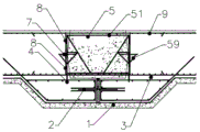
FIG. 2 is a schematic structural diagram of a basement floor post-cast strip in the embodiment before pouring;
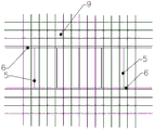
FIG. 3 is a schematic view of the mounting structure of the post-cast strip formwork support in the embodiment.
In the figure: concrete cushion 1, steel plate waterstop 2, bottom reinforcing bar 3, embedded reinforcing bar 4, template support 5, last horizontal pole 51, sheer pole 52, side lever 53, stagnant water board draw-in groove 54, down tube 55, consolidate down tube 56, sleeve 57, spacing groove 58, bracing piece 59, connecting reinforcement 6, stagnant water board 7, steel sheet mesh 8, face reinforcing bar 9.
Detailed Description
The invention is further illustrated with reference to the following figures and examples.
Example (b):
the construction method of the post-cast strip of the underground garage floor provided by the embodiment comprises the following steps: s1, excavating the earthwork, and pouring a concrete cushion layer 1 and a protective layer on the excavated earthwork after the earthwork is excavated to a designed elevation (as shown in figure 1, when the earthwork is excavated, the excavation is continued downwards corresponding to the preset position of the post-cast strip, so that the post-cast strip and the peripheral earthwork form a concave shape, and the poured concrete cushion layer and the protective layer are consistent with the shape of the excavated earthwork); when the concrete cushion layer 1 is poured, a plurality of template supports 5 are prefabricated outside a construction site, the template supports 5 are integrally rectangular, the width of each support is smaller than the preset width of a post-cast strip, each template support comprises an upper cross rod 51, a lower cross rod 52 and two side rods 53 fixed on the left side and the right side of the upper cross rod 51 and the lower cross rod 52, the middle of each side rod 53 is bent towards the inner side direction of the template support to form a water stop plate clamping groove 54, and two vertically arranged sleeves 57 are arranged below the lower cross rod 52 at intervals; s2, measuring and paying off on the protective layer, and marking the position of the post-cast strip by a line; s3, binding bottom-layer steel bars 3 on the protective layer, fixing a plurality of embedded steel bars 4 at intervals on the bottom-layer steel bars 3 at positions indicated by the post-cast strip after the bottom-layer steel bars 3 are bound, wherein the embedded steel bars 4 are vertically arranged and arranged along the preset length direction of the post-cast strip, each post-cast strip corresponds to two rows of embedded steel bars 4, the embedded steel bars 4 on the left side and the right side correspond to each other one by one, and the distance between the two correspondingly arranged embedded steel bars 4 on the left side and the right side is consistent with the distance between two sleeves 57 on the formwork support; s4, fixing the prefabricated formwork support 5 on the bottom layer steel bar 3 one by one (when fixing, aligning the sleeve 57 at the lower end of the formwork support 5 with the embedded steel bar 4, then inserting downwards with force to make the sleeve cover the embedded steel bar), and fixing at least one connecting steel bar 6 at the upper end of the formwork support 5, wherein the connecting steel bar 6 connects all the formwork supports 5 together to form a post-cast strip formwork support, and the water stop plate slots 54 at the left and right sides of the formwork support 5 in the post-cast strip formwork support form a water stop plate installation space at the left and right sides of the post-cast strip formwork support; s5, the water stop plates 7 are clamped in the water stop plate mounting spaces on the left side and the right side, a steel plate net 8 is fixedly mounted on each of the upper side and the lower side of each of the water stop plates 7, the steel plate nets 8 are tightly attached to each of the template supports 5, the water stop plates 7 can be flexible water stop plates or rigid water stop plates, and the flexible water stop plates are more convenient for taking out the template supports; s6, binding plate surface steel bars 9; s7, pouring the basement bottom plate concrete, wherein the pouring is divided into two times during pouring, the pouring is firstly carried out on the position flush with the upper end surfaces of the bottom plate reinforcing steel bars, and then the concrete at the rest positions is poured; and S8, removing the post-cast strip formwork support and the steel plate net 8 after the basement bottom plate concrete is cured and meets the design requirement, and pouring the post-cast strip concrete.
As shown in fig. 2, two diagonal rods 55 are further arranged between the two side rods 53 of the formwork support 5, the upper and lower ends of the two diagonal rods 55 are respectively welded and fixed with the upper cross rod 51 and the lower cross rod 52, and the bent parts of the side rods 53 are welded and fixed with the middle parts of the diagonal rods 55 adjacent to the bent parts. A reinforcing inclined rod 56 is further arranged below the bending part of the side rod 53, and the upper end and the lower end of the reinforcing inclined rod 56 are respectively fixed at the bending part of the side rod and the lower end of the side rod 53 through welding. Two limiting grooves 58 are arranged on the upper cross rod 51 at intervals, and the connecting steel bars 6 are clamped in the limiting grooves 58 and fixed on the formwork support 5 in a binding mode. A support rod 59 is further fixed on the outer sides of the two side rods 53 and below the water stop plate 7, and the upper end of the support rod 59 is positioned below the water stop plate and can support the extending part of the water stop plate.
In specific implementation, in order to have better water stopping effect, a waterproof layer is laid between the concrete cushion layer 1 and the protective layer; a steel plate water stop 2 which is transversely arranged is arranged in the bottom layer reinforcing steel bar 3 and below the preset position of the post-pouring strip.
When the plate surface reinforcing steel bars 9 are bound, the reinforcing steel bars which are parallel to the length direction of the post-cast strip and correspond to the post-cast strip are temporarily not bound; and after the post-cast strip template support and the steel plate net are removed, binding and fixing the steel bars which are not bound at the corresponding positions of the post-cast strip according to the design requirements.
When the post-cast strip formwork support is detached, the connecting steel bars 6 on each post-cast strip formwork are detached and taken out from the gaps of the plate face steel bars 9, then the formwork support 5 and the steel plate net 8 are released from being fixed, and the formwork support 5 is rotated by a certain angle and taken out.
The concrete adopted for pouring the basement bottom plate concrete uses commercial concrete, and pumping is used, so that continuous pouring is ensured without leaving construction joints, the poured concrete reinforcing steel bars, the embedded iron and the like are completely installed, the design requirements are met, and concrete construction can be carried out after acceptance. The pouring is carried out in a layered mode, the thickness of each layer is not more than 400mm, and the initial setting time of the concrete is not more than between the upper layer and the lower layer. Concrete should be reinforced and vibrated, and a special person carries out a side station to avoid concrete from overflowing into a post-cast strip. Covering within 12h after the post-cast strip is poured, maintaining moisture for no less than 28d, and not watering when the daily average temperature is lower than 5 ℃.
Finally, it should be noted that the above embodiments are only used for illustrating the technical solutions of the present invention and not for limiting the technical solutions, and although the present invention has been described in detail by referring to the preferred embodiments, those skilled in the art should understand that modifications or equivalent substitutions to the technical solutions of the present invention can be made without departing from the spirit and scope of the technical solutions, and all the modifications and equivalent substitutions should be covered by the claims of the present invention.
Claims (7)
1. A construction method of a post-cast strip of a bottom plate of an underground garage is characterized by comprising the following steps: s1, excavating the earthwork, and pouring a concrete cushion (1) and a protective layer on the excavated earthwork after the earthwork is excavated to the designed elevation; the method comprises the steps that when a concrete cushion (1) is poured, a plurality of formwork supports (5) are prefabricated outside a construction site, the formwork supports (5) are integrally rectangular, the width of each support is smaller than the preset width of a post-cast strip, each formwork support comprises an upper cross rod (51), a lower cross rod (52) and two side rods (53) fixed to the left side and the right side of the upper cross rod (51) and the lower cross rod (52), the middle of each side rod (53) is bent towards the inner side direction of the formwork support to form a water stop clamping groove (54), and two vertically arranged sleeves (57) are arranged below the lower cross rod (52) at intervals; s2, measuring and paying off on the protective layer, and marking the position of the post-cast strip by a line; s3, binding bottom-layer steel bars (3) on the protective layer, fixing a plurality of embedded steel bars (4) on the bottom-layer steel bars (3) at intervals at the indication positions of the post-cast strip after the bottom-layer steel bars (3) are bound, wherein the embedded steel bars (4) are vertically arranged and arranged along the preset length direction of the post-cast strip, each post-cast strip corresponds to two rows of embedded steel bars (4), the embedded steel bars (4) on the left side and the right side correspond to each other one by one, and the distance between the two correspondingly arranged embedded steel bars (4) on the left side and the right side is consistent with the distance between two sleeves (57) on the template support; s4, fixing the prefabricated formwork supports (5) on the bottom layer steel bars (3) one by one, fixing at least one connecting steel bar (6) at the upper ends of the formwork supports (5), and connecting all the formwork supports (5) together through the connecting steel bar (6) to form a post-cast strip formwork support; the water stop plate clamping grooves (54) on the left side and the right side of the template support (5) in the post-cast strip template support form a water stop plate mounting space on the left side and the right side of the post-cast strip template support, two limiting grooves (58) are arranged on the upper cross rod (51) at intervals, and the connecting steel bars (6) are clamped in the limiting grooves (58) and fixed on the template support (5) in a binding mode; s5, the water stop plates (7) are clamped in the water stop plate mounting spaces on the left side and the right side, a steel plate net (8) is fixedly mounted on the upper portion and the lower portion of each water stop plate (7) respectively, and the steel plate net (8) is tightly attached to each template support (5); s6, binding plate surface steel bars (9); s7, pouring concrete on the basement bottom plate; s8, after the basement bottom plate concrete is cured and meets the design requirements, the post-cast strip formwork support and the steel plate net (8) are dismantled, and then the post-cast strip concrete is poured; when the plate surface steel bars (9) are bound, the steel bars which are parallel to the length direction of the post-cast strip and correspond to the post-cast strip are temporarily not bound; after the formwork support of the post-cast strip and the steel plate net are removed, binding and fixing the steel bars which are not bound at the corresponding position of the post-cast strip according to the design requirement; when the post-cast strip template support is detached, the connecting steel bars (6) on each post-cast strip template need to be detached and taken out from the gaps of the plate face steel bars (9), then the template support (5) and the steel plate net (8) are released from fixation, and the template support (5) is rotated by a certain angle and taken out.
2. The underground garage floor post-cast strip construction method according to claim 1, characterized in that two inclined rods (55) are further arranged between two side rods (53) of the formwork support (5), the upper ends and the lower ends of the two inclined rods (55) are respectively welded and fixed with the upper cross rod (51) and the lower cross rod (52), and the bent parts of the side rods (53) and the middle parts of the adjacent inclined rods (55) are fixed through welding.
3. The underground garage floor post-cast strip construction method according to claim 2, wherein a reinforcing diagonal bar (56) is further arranged below the bent part of the side bar (53), and the upper end and the lower end of the reinforcing diagonal bar (56) are respectively fixed to the bent part of the side bar and the lower end of the side bar (53) through welding.
4. The underground garage floor post-cast strip construction method according to claim 1, characterized in that a support rod (59) is further fixed under the water stop plate (7) outside the two side rods (53), and the upper end of the support rod (59) is positioned under the water stop plate and can support the extending part of the water stop plate.
5. The underground garage floor post-cast strip construction method according to claim 1, characterized in that a waterproof layer is laid between the concrete cushion (1) and the protective layer; a steel plate water stop (2) which is transversely arranged is arranged in the bottom layer steel bar (3) and below the preset position of the post-cast strip.
6. The underground garage floor post-cast strip construction method according to claim 1, wherein the concrete of the basement floor is cast in two times, namely, the concrete is cast to a position flush with the upper end surfaces of the reinforcing steel bars of the floor, and then the concrete is cast to the rest positions.
7. The underground garage floor post-cast strip construction method according to claim 1, wherein the post-cast strip is covered within 12 hours after being poured, is maintained in a moisture-preserving mode for a period of no less than 28 days, and is not watered when the daily average temperature is lower than 5 ℃.
Priority Applications (1)
| Application Number | Priority Date | Filing Date | Title |
|---|---|---|---|
| CN202010365866.8A CN111456105B (en) | 2020-04-30 | 2020-04-30 | Construction method of post-pouring belt of underground garage bottom plate |
Applications Claiming Priority (1)
| Application Number | Priority Date | Filing Date | Title |
|---|---|---|---|
| CN202010365866.8A CN111456105B (en) | 2020-04-30 | 2020-04-30 | Construction method of post-pouring belt of underground garage bottom plate |
Publications (2)
| Publication Number | Publication Date |
|---|---|
| CN111456105A CN111456105A (en) | 2020-07-28 |
| CN111456105B true CN111456105B (en) | 2021-10-08 |
Family
ID=71676991
Family Applications (1)
| Application Number | Title | Priority Date | Filing Date |
|---|---|---|---|
| CN202010365866.8A Active CN111456105B (en) | 2020-04-30 | 2020-04-30 | Construction method of post-pouring belt of underground garage bottom plate |
Country Status (1)
| Country | Link |
|---|---|
| CN (1) | CN111456105B (en) |
Families Citing this family (2)
| Publication number | Priority date | Publication date | Assignee | Title |
|---|---|---|---|---|
| CN114032968B (en) * | 2021-11-25 | 2023-02-14 | 福建永宏建设工程有限公司 | Template component of underground chamber bottom plate post-cast strip |
| CN117230738B (en) * | 2023-11-14 | 2024-02-02 | 山西八建集团有限公司 | Construction device and method for supporting-free disassembly-free formwork of trench cover plate |
Family Cites Families (6)
| Publication number | Priority date | Publication date | Assignee | Title |
|---|---|---|---|---|
| CN202530744U (en) * | 2012-03-27 | 2012-11-14 | 虞建放 | Post-cast strip template structure |
| KR101649904B1 (en) * | 2015-01-26 | 2016-08-22 | 김영조 | Waterstop connector and fabrication method of thereof |
| CN204645615U (en) * | 2015-05-25 | 2015-09-16 | 济南黄河路桥工程公司 | Top board rubber watertight strip fixed mould |
| CN107574842A (en) * | 2016-07-04 | 2018-01-12 | 五冶集团上海有限公司 | Basement post-pouring zone advance water stop construction method |
| CN206599798U (en) * | 2016-12-19 | 2017-10-31 | 江苏龙腾工程设计股份有限公司 | Advanced water-stop post-pouring belt of foundation slab structure |
| CN208009494U (en) * | 2018-01-16 | 2018-10-26 | 江苏中森建筑设计有限公司 | A kind of sole plate pouring after settlement construction |
-
2020
- 2020-04-30 CN CN202010365866.8A patent/CN111456105B/en active Active
Also Published As
| Publication number | Publication date |
|---|---|
| CN111456105A (en) | 2020-07-28 |
Similar Documents
| Publication | Publication Date | Title |
|---|---|---|
| CN109252875B (en) | Existing tunnel lining reinforcing structure and reinforcing method | |
| CN104790302B (en) | A kind of high pier continuous rigid frame bridge end bay straightway Hanging Basket coordinates bent cap support integral construction method | |
| CN110777983A (en) | Synchronous construction structure and method for concrete filled wall and cast-in-place structure | |
| CN103410317A (en) | Construction method for site assembly and casting integral wall body by adopting wall body prefabricated part | |
| CN105649113A (en) | Structure and construction method of basement post-cast strip | |
| CN111456105B (en) | Construction method of post-pouring belt of underground garage bottom plate | |
| CN105275097A (en) | A post-cast strip water-stop steel plate and demolition-free template net installing method | |
| CN205669281U (en) | A kind of cast-in-place integral concrete frame wall filled with masonry system | |
| CN106968692B (en) | Tunnel excavation supporting structure and construction method thereof | |
| CN110284729A (en) | A kind of historical building wall sectional type cutting disassembling method | |
| CN209989847U (en) | Shear force wall post-cast strip prefabricated plate closing device | |
| KR101120588B1 (en) | Vertical joint frame for improving monolithic concrete | |
| CN110847065A (en) | Prefabricated assembled box channel and construction method | |
| CN202509530U (en) | Post-cast strip water stopping steel plate combined structure of foundation bottom plate | |
| CN214530768U (en) | Cast-in-place utility tunnel template bearing structure | |
| CN212388856U (en) | Cast-in-place clear water concrete batter post structure of prestressing force | |
| CN213979911U (en) | Basement outer wall post-cast strip template structure | |
| CN211499326U (en) | Synchronous construction structures of concrete infilled wall and cast-in-place structure | |
| CN212452334U (en) | Arch structure for culvert and reinforced concrete arch plate thereof | |
| CN212053745U (en) | Formwork support frame for post-cast strip construction | |
| CN212223971U (en) | Post-cast strip side-fixing inner-supporting steel plate combined template | |
| CN210508475U (en) | History building unitized wall body with waterproof function | |
| KR102212818B1 (en) | Barrier for concrete pouring | |
| CN113062236A (en) | Wall protection integrated pipe culvert and construction method thereof | |
| CN208717969U (en) | A kind of novel alter-pouring strips mould plate installs structure |
Legal Events
| Date | Code | Title | Description |
|---|---|---|---|
| PB01 | Publication | ||
| PB01 | Publication | ||
| SE01 | Entry into force of request for substantive examination | ||
| SE01 | Entry into force of request for substantive examination | ||
| GR01 | Patent grant | ||
| GR01 | Patent grant |