CN111417481B - Milling cutter tool body with internal offset insert receiving slot, rotary grooving tool with such tool body and cutting insert - Google Patents
Milling cutter tool body with internal offset insert receiving slot, rotary grooving tool with such tool body and cutting insert Download PDFInfo
- Publication number
- CN111417481B CN111417481B CN201880077145.8A CN201880077145A CN111417481B CN 111417481 B CN111417481 B CN 111417481B CN 201880077145 A CN201880077145 A CN 201880077145A CN 111417481 B CN111417481 B CN 111417481B
- Authority
- CN
- China
- Prior art keywords
- blade
- insert
- shank
- cutting
- recess
- Prior art date
- Legal status (The legal status is an assumption and is not a legal conclusion. Google has not performed a legal analysis and makes no representation as to the accuracy of the status listed.)
- Active
Links
Images


Classifications
-
- B—PERFORMING OPERATIONS; TRANSPORTING
- B23—MACHINE TOOLS; METAL-WORKING NOT OTHERWISE PROVIDED FOR
- B23C—MILLING
- B23C5/00—Milling-cutters
- B23C5/02—Milling-cutters characterised by the shape of the cutter
- B23C5/10—Shank-type cutters, i.e. with an integral shaft
- B23C5/109—Shank-type cutters, i.e. with an integral shaft with removable cutting inserts
-
- B—PERFORMING OPERATIONS; TRANSPORTING
- B23—MACHINE TOOLS; METAL-WORKING NOT OTHERWISE PROVIDED FOR
- B23C—MILLING
- B23C5/00—Milling-cutters
- B23C5/006—Details of the milling cutter body
-
- B—PERFORMING OPERATIONS; TRANSPORTING
- B23—MACHINE TOOLS; METAL-WORKING NOT OTHERWISE PROVIDED FOR
- B23C—MILLING
- B23C5/00—Milling-cutters
- B23C5/02—Milling-cutters characterised by the shape of the cutter
- B23C5/08—Disc-type cutters
-
- B—PERFORMING OPERATIONS; TRANSPORTING
- B23—MACHINE TOOLS; METAL-WORKING NOT OTHERWISE PROVIDED FOR
- B23C—MILLING
- B23C5/00—Milling-cutters
- B23C5/16—Milling-cutters characterised by physical features other than shape
- B23C5/20—Milling-cutters characterised by physical features other than shape with removable cutter bits or teeth or cutting inserts
- B23C5/22—Securing arrangements for bits or teeth or cutting inserts
- B23C5/2239—Securing arrangements for bits or teeth or cutting inserts with cutting inserts clamped by a clamping member acting almost perpendicular on the cutting face
-
- B—PERFORMING OPERATIONS; TRANSPORTING
- B23—MACHINE TOOLS; METAL-WORKING NOT OTHERWISE PROVIDED FOR
- B23C—MILLING
- B23C5/00—Milling-cutters
- B23C5/16—Milling-cutters characterised by physical features other than shape
- B23C5/20—Milling-cutters characterised by physical features other than shape with removable cutter bits or teeth or cutting inserts
- B23C5/22—Securing arrangements for bits or teeth or cutting inserts
- B23C5/2298—Securing arrangements for bits or teeth or cutting inserts secured by resilient/flexible means
-
- B—PERFORMING OPERATIONS; TRANSPORTING
- B23—MACHINE TOOLS; METAL-WORKING NOT OTHERWISE PROVIDED FOR
- B23C—MILLING
- B23C5/00—Milling-cutters
- B23C5/28—Features relating to lubricating or cooling
-
- B—PERFORMING OPERATIONS; TRANSPORTING
- B23—MACHINE TOOLS; METAL-WORKING NOT OTHERWISE PROVIDED FOR
- B23C—MILLING
- B23C5/00—Milling-cutters
- B23C5/28—Features relating to lubricating or cooling
- B23C5/283—Cutting inserts with internal coolant channels
-
- B—PERFORMING OPERATIONS; TRANSPORTING
- B23—MACHINE TOOLS; METAL-WORKING NOT OTHERWISE PROVIDED FOR
- B23C—MILLING
- B23C2200/00—Details of milling cutting inserts
- B23C2200/04—Overall shape
- B23C2200/0494—Rectangular
-
- B—PERFORMING OPERATIONS; TRANSPORTING
- B23—MACHINE TOOLS; METAL-WORKING NOT OTHERWISE PROVIDED FOR
- B23C—MILLING
- B23C2200/00—Details of milling cutting inserts
- B23C2200/08—Rake or top surfaces
- B23C2200/082—Rake or top surfaces with an elevated clamping surface
-
- B—PERFORMING OPERATIONS; TRANSPORTING
- B23—MACHINE TOOLS; METAL-WORKING NOT OTHERWISE PROVIDED FOR
- B23C—MILLING
- B23C2200/00—Details of milling cutting inserts
- B23C2200/08—Rake or top surfaces
- B23C2200/085—Rake or top surfaces discontinuous
-
- B—PERFORMING OPERATIONS; TRANSPORTING
- B23—MACHINE TOOLS; METAL-WORKING NOT OTHERWISE PROVIDED FOR
- B23C—MILLING
- B23C2200/00—Details of milling cutting inserts
- B23C2200/08—Rake or top surfaces
- B23C2200/086—Rake or top surfaces with one or more grooves
-
- B—PERFORMING OPERATIONS; TRANSPORTING
- B23—MACHINE TOOLS; METAL-WORKING NOT OTHERWISE PROVIDED FOR
- B23C—MILLING
- B23C2200/00—Details of milling cutting inserts
- B23C2200/16—Supporting or bottom surfaces
- B23C2200/164—Supporting or bottom surfaces discontinuous
-
- B—PERFORMING OPERATIONS; TRANSPORTING
- B23—MACHINE TOOLS; METAL-WORKING NOT OTHERWISE PROVIDED FOR
- B23C—MILLING
- B23C2200/00—Details of milling cutting inserts
- B23C2200/16—Supporting or bottom surfaces
- B23C2200/165—Supporting or bottom surfaces with one or more grooves
-
- B—PERFORMING OPERATIONS; TRANSPORTING
- B23—MACHINE TOOLS; METAL-WORKING NOT OTHERWISE PROVIDED FOR
- B23C—MILLING
- B23C2210/00—Details of milling cutters
- B23C2210/02—Connections between the shanks and detachable cutting heads
-
- B—PERFORMING OPERATIONS; TRANSPORTING
- B23—MACHINE TOOLS; METAL-WORKING NOT OTHERWISE PROVIDED FOR
- B23C—MILLING
- B23C2210/00—Details of milling cutters
- B23C2210/03—Cutting heads comprised of different material than the shank irrespective of whether the head is detachable from the shank
-
- B—PERFORMING OPERATIONS; TRANSPORTING
- B23—MACHINE TOOLS; METAL-WORKING NOT OTHERWISE PROVIDED FOR
- B23C—MILLING
- B23C2210/00—Details of milling cutters
- B23C2210/16—Fixation of inserts or cutting bits in the tool
- B23C2210/161—Elastically deformable clamping members
-
- B—PERFORMING OPERATIONS; TRANSPORTING
- B23—MACHINE TOOLS; METAL-WORKING NOT OTHERWISE PROVIDED FOR
- B23C—MILLING
- B23C2210/00—Details of milling cutters
- B23C2210/20—Number of cutting edges
- B23C2210/202—Number of cutting edges three
-
- B—PERFORMING OPERATIONS; TRANSPORTING
- B23—MACHINE TOOLS; METAL-WORKING NOT OTHERWISE PROVIDED FOR
- B23C—MILLING
- B23C2210/00—Details of milling cutters
- B23C2210/40—Flutes, i.e. chip conveying grooves
-
- B—PERFORMING OPERATIONS; TRANSPORTING
- B23—MACHINE TOOLS; METAL-WORKING NOT OTHERWISE PROVIDED FOR
- B23C—MILLING
- B23C2250/00—Compensating adverse effects during milling
- B23C2250/12—Cooling and lubrication
Landscapes
- Engineering & Computer Science (AREA)
- Mechanical Engineering (AREA)
- Milling Processes (AREA)
- Cutting Tools, Boring Holders, And Turrets (AREA)
- Drilling Tools (AREA)
- Perforating, Stamping-Out Or Severing By Means Other Than Cutting (AREA)
- Gripping On Spindles (AREA)
- Surgical Instruments (AREA)
Abstract
A milling tool body (22) includes a disc-shaped cutter portion (26) and a shank portion (56) projecting rearwardly therefrom. The cutter portion (26) includes a resilient clamping portion (32) provided with an insert receiving slot (38) at its outer periphery. The shank portion (56) includes a front shank recess (60) provided on the outer periphery adjacent to the tool portion (26) in the axial direction. A radially inner portion of the insert receiving groove (38) merges with the front shank recess (60) in the rearward direction. The cutting insert (24) is removably and resiliently clamped in the insert receiving slot (38) to form the rotary grooving tool (20). The cutting insert (24) includes two cutting portions (94 a,94 b) each having long and short insert lateral extensions (98 a,98 b), the long insert lateral extension (98 a) being longer than the short insert lateral extension (98 b). The longest blade lateral extension (98 a) is located on opposite sides of the cutting blade (24).
Description
Technical Field
The subject matter of the present application relates generally to rotary grooving tools having a grooving tool body having a disk-shaped tool portion with a plurality of circumferentially disposed insert receiving grooves for removably retaining a cutting insert therein, and in particular, to such a grooving tool body in which the insert receiving grooves resiliently clamp the cutting insert therein.
Background
The rotary grooving tool may have a grooving tool body having a disk-shaped cutting tool portion and a shank extending perpendicular to the disk-shaped cutting tool portion. The disc cutter portion may be provided with a plurality of circumferentially arranged insert receiving slots for retaining cutting inserts therein. The cutting insert may be secured in the insert receiving pocket by a set screw. Examples of such rotary cutting tools are disclosed, for example, in US6,571,451 and US8,834,075.
In other rotary grooving tools, the cutting insert may be secured in the insert-receiving slot by a resilient clamping member. Examples of such rotary cutting tools are disclosed, for example, in US6,116,823 and US8,708,610, wherein the cutting insert is single ended. Alternatively, the cutting insert may also be double ended, as shown in US5,059,068.
In other rotary grooving tools, particularly for internal grooving in small holes, a disc-shaped solid carbide grooving head having a plurality of cutting edges may be preferably used. Examples of such rotary cutting tools are disclosed, for example, in US6,276,879 and US8,708,611. However, such a milling head is relatively expensive to manufacture and if one cutting edge is damaged, the entire milling head needs to be replaced.
Disclosure of Invention
According to a first aspect of the subject matter of the present application, there is provided a slotting tool body having a body central axis defining opposite forward and rearward directions, and being rotatable about the body central axis in a rotational direction, the slotting tool body comprising:
a disc-shaped cutter portion including an elastic clamping portion having an insert receiving groove provided on an outer periphery; and
a shank portion protruding rearward from the tool portion, the shank portion including a shank peripheral surface extending circumferentially about the main body central axis and a front shank recess recessed into the shank peripheral surface adjacent the tool portion and opening to the shank peripheral surface, wherein:
the radially inner portion of the insert receiving slot merges with the forward shank recess in a rearward direction.
According to a second aspect of the subject matter of the present application, there is provided a rotary grooving tool comprising:
a milling tool body of the type described above; and
a cutting insert removably and resiliently clamped in the insert receiving slot.
According to a third aspect of the subject matter of the present application, there is provided a cutting insert longitudinally elongated in a direction defining an insert longitudinal axis and comprising:
Opposite blade upper and lower surfaces and a blade peripheral surface extending therebetween, the blade peripheral surface including opposite two blade end surfaces connecting the blade upper and lower surfaces and opposite two blade side surfaces also connecting the blade upper and lower surfaces;
a blade longitudinal plane comprising a blade longitudinal axis passing between blade side surfaces and intersecting the blade upper surface and the blade lower surface and also intersecting the opposing blade end surfaces; and
two cutting portions at opposite ends of the cutting insert, each including a cutting edge formed at an intersection between an upper surface of the insert and one of two insert end surfaces, wherein:
the cutting portions of the blades each include two blade lateral extensions projecting laterally from opposite sides of the cutting blade in a direction away from the longitudinal plane of the blade and onto which the cutting edges extend;
the two blade lateral extensions include a wide blade lateral extension and a narrow blade lateral extension, the wide blade lateral extension being longer than the narrow blade lateral extension in a direction perpendicular to the blade longitudinal plane; and is also provided with
The wide blade lateral extensions are located on opposite sides of the blade longitudinal plane.
According to a fourth aspect of the subject matter of the present application, there is provided a cutting tool body having a body central axis defining opposite forward and rearward directions, and a slot milling tool body rotatable about the body central axis in a rotational direction, the slot milling tool body comprising:
a disc-shaped cutter portion including an elastic clamping portion having an insert receiving groove provided on an outer periphery; and
a shank portion protruding rearward from the tool portion, the shank portion including a shank peripheral surface extending circumferentially about the main body central axis and a front shank recess recessed into the shank peripheral surface adjacent the tool portion and opening to the shank peripheral surface, wherein:
in a front view of the milling tool body, the shank is visible through the insert receiving slot portion in a direction along the central axis of the body.
It should be understood that the foregoing is an overview and that the features described hereinafter may be applied to the subject matter of the present application in any combination, e.g., any of the following features may be applied to the milling tool body and the rotary grooving tool and the cutting insert:
The cutter portion and the shank portion may be integrally formed such that the slot milling tool body has a unitary one-piece construction.
The clamping portion may further include a resilient clamping member and a lower jaw member opposite each other and spaced apart from each other by the insert receiving slot, the resilient clamping member being disposed forward of the lower jaw member in a rotational direction and configured to resiliently secure the cutting insert in the insert receiving slot.
The resilient clamping member may axially abut the front shank recess.
The shank portion may include a non-recessed front shank portion disposed on the outer periphery that circumferentially adjoins the front shank recess and axially adjoins the tool portion.
The tool portion may further comprise at least one additional resilient clamping portion to form a plurality of clamping portions angularly spaced apart from each other. The handle may also include at least one additional front handle recess to form a plurality of front handle recesses angularly spaced apart from one another. The shank may further comprise at least one additional non-recessed front shank portion to form a plurality of non-recessed front shank portions angularly spaced apart from one another, each non-recessed front shank portion being located between two circumferentially adjacent front shank recesses. The radially inner portion of each insert receiving slot may merge with the corresponding forward shank recess in a rearward direction.
In a direction along the central axis of the body:
an imaginary radius line extending between the body central axis and the furthest portion on the non-recessed front shank defines a shank radius of a shank circle centered about the body central axis and having a shank diameter; and is also provided with
The cutter portion defines a cutter portion circumscribed circle centered about the body central axis and having a cutter portion diameter.
The shank circle may intersect the insert receiving slot in a direction along the body central axis.
The blade receiving slot may be defined by an elongated slot peripheral surface including a slot lower jaw abutment surface on the lower jaw member. The shank circle intersects the pocket lower jaw abutment surface in a direction along the body central axis.
The groove peripheral surface may further include a groove clamping member abutment surface on the resilient clamping member. The groove gripping member abutment surface may be located radially outward of the shank circle in a direction along the body central axis.
The groove peripheral surface may further include a groove radial stop surface located circumferentially between the groove gripping member abutment surface and the groove lower jaw abutment surface. The groove radial stop surface may be located radially inward of the shank circle in a direction along the body central axis.
The front shank recess may further include a recess outer side gap provided on the outer periphery, defined by a forwardly facing recess outer side base surface and a recess outer side peripheral surface extending transversely to the recess outer side base surface, each end of the recess outer side peripheral surface and the recess outer side base surface intersecting the shank outer peripheral surface.
The front handle recess may include a recess inner gap defined by a forwardly facing recess inner base surface and a recess inner peripheral surface extending transverse to the recess inner base surface. The recess inner base surface may intersect the recess outer peripheral surface. Each end of the recess inner side peripheral surface may intersect with the recess outer side peripheral surface.
The recess outside gap may be formed by a circumferential groove extending in the circumferential direction.
The recess outer peripheral surface may be concavely curved in a direction along the main body central axis and defined by a recess outer peripheral radius.
In a side view of the milling tool body, the recess outer peripheral surface may be concavely curved and defined by an outer peripheral side radius.
The cutting insert may be longitudinally elongated in a direction defining an insert longitudinal axis, and the cutting insert may include:
Opposite blade upper and lower surfaces and a blade peripheral surface extending therebetween, the blade peripheral surface including opposite two blade end surfaces connecting the blade upper and lower surfaces and opposite two blade side surfaces also connecting the blade upper and lower surfaces;
a blade longitudinal plane comprising a blade longitudinal axis passing between blade side surfaces and intersecting the blade upper surface and the blade lower surface and also intersecting the opposing blade end surfaces; and
a cutting portion at one end of the cutting insert, the cutting portion comprising a cutting edge formed at an intersection between an insert upper surface and one of two insert end surfaces, wherein:
the insert end surface opposite the cutting portion includes an insert pocket including an insert key surface that is closer to the insert lower surface than to the insert upper surface, the insert key surface being configured to be abutted by a displacement fork of a key for removing the cutting insert from the insert receiving slot.
In a side view of the cutting insert, the insert key surface may be concavely curved.
The blade wrench surface may be located entirely below a blade mid-plane extending at a midpoint between the blade upper surface and the blade lower surface and including the blade longitudinal axis.
The insert end surface opposite the cutting portion may further comprise an insert stop surface closer to the insert upper surface than to the insert lower surface, the insert stop surface being planar.
The cutting insert may include additional cutting portions forming two cutting portions formed at opposite ends of the cutting insert.
The blade cutting portions may each comprise two blade lateral extensions projecting laterally from opposite sides of the cutting blade in a direction away from the longitudinal plane of the blade and onto which the cutting edges extend. The two blade lateral extensions may comprise a wide blade lateral extension and a narrow blade lateral extension, the wide blade lateral extension being longer than the narrow blade lateral extension in a direction perpendicular to the blade longitudinal plane. The wide blade lateral extension may be located on opposite sides of the blade longitudinal plane.
The two cutting portions may include a working cutting portion and a non-working cutting portion, the cutting edge of the working cutting portion being located outside the radial extent of the cutter portion. The wide insert lateral extension of the working cutting portion may be the axially forward-most portion of the two insert lateral extensions with respect to the axial direction.
The insert receiving slot may comprise a slot insert portion defined by an insert contour of the cutting insert in a direction along the central axis of the body. The radially inner portion of the pocket insert portion may merge with the front shank recess in the rearward direction.
Drawings
For a better understanding of the present application and to show how it may be carried into effect, reference will now be made to the accompanying drawings, in which:
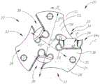
FIG. 1 is a front perspective view of a rotary grooving tool according to the present application, wherein a cutting insert is resiliently clamped in an insert receiving groove;
FIG. 2 is an exploded rear perspective view of the rotary slitting tool shown in FIG. 1;
FIG. 3 is a front view of the milling tool body of FIG. 1;
FIG. 4 is a side view of the milling tool body shown in FIG. 3;
FIG. 5 is a side view of the clamping portion of FIG. 3 with an insert contour superimposed thereon;
FIG. 6 is a front view of the clamping portion of FIG. 5 along directional line "VI";
FIG. 7 is a perspective view of a cutting insert according to the present application;
FIG. 8 is a side view of the cutting insert shown in FIG. 7;
FIG. 9 is a top view of the cutting insert shown in FIGS. 7 and 8; and
fig. 10 is a view similar to that shown in fig. 1, prior to the cutting insert being pulled out of the insert receiving pocket with a wrench.
It will be appreciated that for simplicity and clarity of illustration, elements shown in the figures have not necessarily been drawn to scale. For example, the dimensions of some of the elements may be exaggerated relative to other elements for clarity, or several physical components may be included in one functional block or element. Further, where considered appropriate, reference numerals may be repeated among the figures to indicate corresponding or analogous elements.
Detailed Description
In the following description, various aspects of the subject matter of the present application will be described. For purposes of explanation, specific configurations and details are set forth in sufficient detail to provide a thorough understanding of the subject matter of the present application. However, it will be apparent to one skilled in the art that the subject matter of the present application may be practiced without the specific construction and details presented herein.
Referring first to fig. 1 and 2, a rotary grooving tool 20 suitable for grooving operations depicting one aspect of the present application is shown having a tool central axis a. The rotary grooving tool 20 may exhibit rotational symmetry about the tool central axis a. The rotary slotting tool 20 has a slotting tool body 22 which may be generally made of steel. The rotary grooving tool 20 has a cutting insert 24, which may typically be made of cemented carbide. The cutting insert 24 is removably attached to the milling tool body 22.
It should be noted that the word "rotary grooving tool" as used herein may be replaced with other words suitable for use in such cutting tools in the art of metal cutting, such as "slotting cutter", and "grooving cutter" "slot milling cutter", "trench milling cutter", "side milling cutter", "disc milling cutter", etc.
Referring now also to fig. 3 and 4, another aspect of the subject matter of the present application is shown that relates to a milling tool body 22. The slot milling tool body 22 has a body central axis B that coincides with the tool central axis a. The body central axis B defines an opposite forward direction D F And a backward direction D R . The body central axis B forms an axis of rotation about which the milling tool body 22 is rotatable in a direction of rotation R.
It should be understood that throughout the specification and claims, the use of the words "forward" and "rearward" refer to relative positions in the downward and upward directions of the body central axis B in fig. 4, respectively. Furthermore, unless otherwise indicated, the words "axial" and "radial" are with respect to the tool central axis B.
As shown in fig. 3, the milling tool body 22 includes a disc-shaped cutter portion 26. The cutter portion 26 includes two opposing cutter portion side surfaces 28 and a cutter portion peripheral surface 30 extending between the cutter portion side surfaces 28. The cutter portion outer peripheral surface 30 extends in the circumferential direction about the body central axis B. The body center axis B intersects both tool portion side surfaces 28 at their center portions. In a front view of the milling tool body 22, in a direction along the body central axis B (i.e., fig. 3), the cutter portion 26 defines a cutter portion circumscribed circle CC centered about the body central axis B and having a cutter portion diameter DC.
As shown in fig. 4, the cutter portion 26 has a cutter portion width WC measured between the two cutter portion side surfaces 28 in the axial direction. According to some embodiments of the subject matter of the present application, the two cutter portion side surfaces 28 may be planar and perpendicular to the body central axis B. The tool portion 26 may include a pivot fork aperture 31 for receiving a pivot fork 51b of a wrench 52 when the cutting insert 24 is removed from the tool portion 26, as discussed later in the specification.
The cutter portion 26 includes a clamping portion 32. According to some embodiments of the subject matter of the present application, the cutter portion 26 may also include at least one additional clamping portion 32 to form a plurality of clamping portions 32 angularly spaced apart from one another. It will be appreciated in the following description that any feature associated with a single clamp portion 32 may also be associated with other clamp portions 32 (if present). The plurality of clamping portions 32 may be disposed at the same axial position along the main body central axis B in the forward-rearward direction. Each clamping portion 32 may have a chip flute 33 at the tool portion peripheral surface 30, such that the tool portion 26 may not be entirely circular in front view.
Clamping portion 32 includes a resilient clamping member 34 and a lower jaw member 36 that are opposed to one another and are spaced apart from one another by a blade-receiving slot 38. That is, a blade receiving slot 38 is formed between the resilient clamping member 34 and the lower jaw member 36. The insert receiving slot 38 extends along an insert receiving slot axis C such that the resilient clamping member 34 and the lower jaw member 36 are located on opposite sides of the insert receiving slot axis C in a front view of the slot milling tool body 22. The resilient clamping member 34 is disposed forwardly of the lower jaw member 36 and the blade-receiving slot 38 in the rotational direction. The resilient clamping member 34 is configured to resiliently secure the cutting insert 24 in the insert receiving slot 38. Resilient clamping member 34 is resiliently displaceable relative to lower jaw member 36. In other words, the clamping portion 32 is elastic. It should be noted that the clamping portion 32 does not have the elastic groove disclosed in US6,116,823 and US8,388,270 provided in front of the elastic clamping member 34 in the rotational direction.
With further reference to fig. 5, which shows a side view of the clamping portion 32 (i.e., perpendicular to the insert receiving slot axis C), the insert receiving slot 38 opens to the cutter portion peripheral surface 30. Thus, the blade receiving slot 38 is provided on the outer periphery. Returning to fig. 4, the insert receiving slot 38 opens laterally on both sides to the cutter portion side surface 28. It should be understood that the context of "laterally" in reference to the insert-receiving slot 38 refers to being perpendicular to the insert-receiving slot axis C and thus generally in a direction parallel to the body central axis B.
The insert receiving slot 38 is defined by an elongated slot peripheral surface 40, the ends of which extend to the cutter portion peripheral surface 30. The groove peripheral surface 40 extends between the two cutter portion side surfaces 28. The pocket peripheral surface 40 includes a pocket clamping member abutment surface 42 on the resilient clamping member 34 for abutment against a corresponding surface on the cutting insert 24. The pocket peripheral surface 40 includes a pocket lower jaw abutment surface 44 on the lower jaw member 36 for abutment against a corresponding surface on the cutting insert 24. The pocket peripheral surface 40 includes a pocket radial stop surface 46 for positioning the cutting insert 24 at a precise predetermined radial position. The groove radial stop surface 46 faces radially outward. According to some embodiments of the subject matter of the present application, a groove radial stop surface 46 may be positioned circumferentially between the groove clamping member abutment surface 42 and the groove lower jaw abutment surface 44.
Referring to fig. 5, the insert receiving slot 38 includes a slot insert portion 48 defined by an insert profile IP of the cutting insert 24 in a direction along the body central axis B when it is removably and resiliently clamped in the insert receiving slot 38. The blade receiving slot 38 includes a slot spanner portion 50 extending radially inward from the blade receiving slot 38. One purpose of the slot spanner portion 50 is to act as a stress relief slot (as is known in the art). However, the slot spanner portion 50 has a larger size than a normal stress relief slot such that it may also be used to receive the displacement fork 51a of the spanner 52 when the cutting insert 24 is removed from the insert receiving slot 38. Furthermore, if the slot spanner portion 50 is used only as a stress relief slot, it is positioned further forward in the rotational direction than is normally required. For example, a majority of the blade lever portion 50 is located above the extension of the under-slot jaw abutment surface 44. This enables the displacement fork 51a to abut the end of the cutting insert 24 while being located in the slot spanner portion 50. The insert receiving slot 38 includes a slot spring portion 54 for providing a desired spring force to the resilient clamping member 34. The slot elastic portion 54 is provided in front of the slot spanner portion 50 in the rotational direction.
Referring to fig. 2-4, the slot milling tool body 22 includes a shank portion 56 protruding from the rearmost cutter portion side surface 28. That is, the shank portion 56 protrudes rearward from the cutter portion 26. The shank 56 includes a shank peripheral surface 58 extending circumferentially about the body central axis B. According to some embodiments of the subject matter of the present application, shank portion 56 may be integrally formed with cutter portion 26 such that slot milling tool body 22 has a unitary, one-piece structure, i.e., shank portion 56 and cutter portion 26 are formed (e.g., machined) from a single, continuous piece of material. The handle 56 may have a cylindrical basic shape. As shown in fig. 4, the shank peripheral surface 58 may intersect the tool side surface 28 at a shank rounded corner surface 59 having a concave curvature. The concave curve may have a stem fillet radius RF greater than or equal to 1mm and less than or equal to 2 mm.
Returning to fig. 4 and 6, the shank 56 includes a front shank recess 60 recessed into the shank peripheral surface 58 and open to the shank peripheral surface 58. That is, the front shank recess 60 is provided on the outer periphery and is recessed therein in the radial direction at a position closest to the front end of the shank outer peripheral surface 58. The shank recess 60 axially abuts the cutter portion 26. According to some embodiments of the subject matter of the present application, the shank 56 may further include at least one additional forward shank recess 60 to form a plurality of forward shank recesses 60 angularly spaced from one another. It should be appreciated in the following description that any feature associated with a single stem recess 60 may also be associated with other stem recesses 60 (if present).
According to some embodiments of the subject matter of the present application, the shank 56 may include a non-recessed front shank 62 formed by a non-recessed portion of the shank peripheral surface 58. As with the front shank recess 60, a non-recessed front shank portion 62 is provided on the outer periphery. The non-recessed forward shank portion 62 may circumferentially abut the forward shank recess 60 and axially abut the cutter portion 26. Thus, the front shank recess 60 may not extend around the entire circumferential extent of the shank 56 (i.e., may not have an angular extent of 360 °). In accordance with some embodiments of the subject matter of the present application, in a similar manner to the front shank recess 60, the shank 56 may also include at least one additional non-recessed front shank 62 to form a plurality of non-recessed front shanks 62 angularly spaced apart from one another. The number of non-recessed front handle portions 62 may be matched to the number of front handle recesses 60. Each non-recessed front shank portion 62 may be located between two circumferentially adjacent front shank recesses 60. That is, the front shank recess 60 and the non-recessed front shank 62 may alternate in the circumferential direction. It should be appreciated in the foregoing description that any feature associated with a single non-recessed front handle 62 is also associated with other non-recessed front handles 62 (if present).
As shown in fig. 3, an imaginary radial line extending between the body central axis B and the farthest portion on the non-recessed front shank 62 in a direction along the body central axis B defines a shank radius RS of a shank circle CS centered on the body central axis B and having a shank diameter DS. In a configuration having a plurality of non-recessed front shanks 62, the shank circle CS is a circumscribed circle defined by the plurality of non-recessed front shanks 62. Note that if the shank peripheral surface 58 has rounded corners as described above, the shank diameter DS may be different from (e.g., larger than) the diameter of an circumscribed circle (not shown) defined by the shank 56 obtained at a position further rearward in the axial direction.
According to some embodiments of the subject matter of the present application, the resilient clamping member 34 may axially abut the front shank recess 60. That is, the free end of the resilient clamping member 34 is not connected to any portion of the handle 56. As shown in fig. 2, the rearward facing surface 34a of the clamping member 34 faces the forward shank recess 60. At the front shank recess 60, the elastic clamping member 34 is cantilevered in a circumferential direction relative to the non-recessed front shank 62 forward in the rotational direction in a direction opposite the rotational direction R. Advantageously, this allows the resilient clamping member 34 to flex slightly (along with the lower jaw member 36 and the cutting insert 24) when the cutting insert 24 contacts a workpiece to maintain a firm clamping force on the cutting insert 24. A radially inner portion of lower jaw member 36 may be connected to non-recessed front handle 62.
Referring back to fig. 5, according to some embodiments of the subject matter of the present application, the front shank recess 60 may include a recess outer side gap 64 defined by a forwardly facing recess outer side base surface 66 and a recess outer side peripheral surface 68 extending transverse to the recess outer side base surface 66. Each end of the recess outer base surface 66 and the recess outer peripheral surface 68 may intersect the shank peripheral surface 58. Accordingly, the recess outside gap 64 is provided on the outer periphery. The ends of the recess outer peripheral surface 68 intersect the shank outer peripheral surface 58 at two peripheral intersections 72, the two peripheral intersections 72 subtending a recess outer clearance angle δ (shown in fig. 3) at the body central axis B. The recess outside clearance angle δ may be in the range of 60 ° or more and δ or less than 80 °. The recess outside gap 64 may be formed by a circumferential groove that may extend in the circumferential direction. The recess outer peripheral surface 68 may be concavely curved in a direction along the main body central axis B, and may be defined by a recess outer peripheral radius RO. In a side view of the milling tool body 22 (perpendicular to the body central axis B), the recess outer peripheral surface 68 may be concavely curved and may be defined by an outer peripheral side radius RS. As seen in fig. 6, which shows a front view of the clamping portion 32 along the insert receiving slot axis C, in the axial direction, the recess outer gap 64 has a recess outer gap width WO measured between the cutter portion 26 and the recess outer base surface 66. The recess outside gap width WO may be substantially twice the outer circumference side radius RS.
According to some embodiments of the subject matter of the present application, the front shank recess 60 may include a recess inner side gap 74 defined by a forwardly facing recess inner side base surface 76 and a recess inner side peripheral surface 78 extending transverse to the recess inner side base surface 76. The recess inner base surface 76 may intersect the recess outer peripheral surface 68. Each end of the recess inner peripheral surface 78 may intersect the recess outer peripheral surface 68. In general, the recess inner gap 74 is radially inward relative to the recess outer gap 64. The groove outer peripheral surface 40 and the groove elastic portion 54 at the groove key portion 50 can uniformly and continuously transition into the recess inner peripheral surface 78. Likewise, the groove radial stop surface 46 may transition uniformly and continuously into the recess inner peripheral surface 78. Accordingly, the groove outer peripheral surface 40 at the groove key portion 50, as well as the groove elastic portion 54 and the groove radial stopper surface 46, can be aligned with the recess inner side outer peripheral surface 78 in the direction along the main body central axis B. As seen in fig. 6, the recess inner gap 74 has a recess inner gap width WI measured between the cutter portion 26 and the recess inner base surface 76 in the axial direction.
According to some embodiments of the subject matter of the present application, the recess outside gap width WO may be greater than or equal to 1mm and less than or equal to 2mm (1 mm. Ltoreq.WO. Ltoreq.2 mm). The recess inside gap width WI may be smaller than the recess outside gap width WO (WI < WO). That is, the recess inner side gap 74 may be narrower than the recess outer side gap 64 in the axial direction. The recess outside gap width WO may be smaller than the cutter portion width WC (WO < WC). That is, the recess outside clearance 64 may be narrower than the cutter portion 26 in the axial direction.
The radially inner portion of the insert receiving slot 38 is on one side (i.e., the rearmost one of the two cutter portion side surfaces 28 of the insert receiving slot 38, i.e., in the rearward direction D R Upper open side) laterally merges with the front shank recess 60. Thus, the blade receiving slot 38 is offset inwardly. Obviously, in the configuration having the plurality of clamping portions 32 and the plurality of front shank recesses 60, the radially inner portion of each insert receiving slot 38 is in the rearward direction D R And merges with a corresponding front shank recess 60. In a front view of the milling tool body 22, the shank 56 is partially visible in a direction along the body central axis B. More specifically, shank portion 56 is partially visible through pocket blade portion 48. Thus, the forward shank recess 60 is partially concealed when the cutting insert 24 is removably and resiliently clamped in the insert receiving slot 38.
According to some embodiments of the subject matter of the present application, the shank circle CS may intersect the insert receiving slot 38 in a direction along the body central axis B. In particular, the shank circle CS may intersect the pocket insert portion 48. Accordingly, the radially inner portion of the pocket blade portion 48 may be in the rearward direction D R And merges with the front shank recess 60. Further specifically, the shank circle CS may intersect the under-slot jaw abutment surface 44. The groove gripping member abutment surface 42 may be located radially outward of the shank circle CS. The groove radial stop surface 46 may be located radially inward of the shank circle CS. The slot spanner portion 50 and the slot spring portion 54 may be located radially inward of the shank circle CS.
Referring to fig. 2 and 6, according to some embodiments of the subject matter of the present application, shank 56 may include a shank coolant channel 80 opening to shank peripheral surface 58 at coolant channel outlet 82. The coolant passage outlet 82 may intersect the front shank recess 60.
Referring now to fig. 7-9, another aspect of the subject matter of the present application is shown that relates to a cutting insert 24. The cutting insert 24 is elongated longitudinally in a direction defining an insert longitudinal axis a. The cutting insert 24 includes opposed insert upper and lower surfaces 84, 86 and an insert peripheral surface 88 extending therebetween. The insert upper surface 84 and insert lower surface 86 include an insert upper abutment surface 84a and insert lower abutment surface 86b, respectively, for abutment with corresponding surfaces on the insert receiving slot 38. According to some embodiments of the subject matter of the present application, the blade lower surface 86 may include a straight blade imaginary line L parallel to the blade longitudinal axis a. The upper insert abutment surface 84a and/or the lower insert abutment surface 86b may have a prismatic shape that matches the shape of the pocket clamping member abutment surface 42 and/or the lower pocket jaw abutment surface 44, respectively, to prevent displacement of the cutting insert 24 in the lateral direction of the cutting insert 24.
The insert peripheral surface 88 includes two opposing insert end surfaces 90 that connect the insert upper surface 84 and the insert lower surface 86. The insert peripheral surface 88 includes two opposing insert side surfaces 92 that connect the insert upper surface 84 and the insert lower surface 86. The insert longitudinal axis a intersects the insert end surface 90 and extends between the insert side surfaces 92 (fig. 9) and also extends between the insert upper surface 84 and the insert lower surface 86 (fig. 8). The insert transverse axis E extends perpendicular to the insert longitudinal axis a at a midpoint between the insert end surfaces 90 and intersects the two insert side surfaces 92, thereby defining an insert transverse direction of the cutting insert 24. The insert central axis F extends perpendicular to the insert longitudinal axis a at a midpoint between the insert end surfaces 90 and intersects the insert upper surface 84 and the insert lower surface 86. The blade mid-plane M contains the blade longitudinal axis a and the blade transverse axis E.
As shown in fig. 9, the insert longitudinal axis a lies on an insert longitudinal plane P1 containing the insert central axis F, passes through at a midpoint between the insert side surfaces 92, and intersects the two end surfaces 90. The blade center plane P2, which is perpendicular to the blade longitudinal plane P1 and also perpendicular to the blade longitudinal axis a, contains the blade center axis F and the blade lateral axis E. According to some embodiments of the subject matter of the present application, the cutting insert 24 may have a rotational symmetry of 180 ° about the insert central axis F. The cutting insert 24 may not be mirror symmetrical about the insert center plane P2 or the insert longitudinal plane P1.
The cutting insert 24 includes a cutting portion 94a at one end of the cutting insert 24. According to some embodiments of the subject matter of the present application, the cutting insert 24 may further include one additional cutting portion 94b to form two cutting portions 94a, 94b, namely a working cutting portion 94a and a non-working cutting portion 94b. Two cutting portions 94a, 94b are located at opposite ends of the cutting insert 24. In other words, the cutting insert 24 is double ended and may be indexed by rotating 180 ° about the insert central axis F (i.e., the active cutting portion 94a becomes the inactive cutting portion 94b and vice versa). The two cutting portions 94a, 94b may be identical. It should be appreciated in the following description that any feature associated with a single cutting portion 94a may also be associated with another cutting portion 94b (if present).
The cutting portion 94a includes a cutting edge 96 formed at the intersection between the insert upper surface 84 and one of the two insert end surfaces 90. The portion of the insert end surface 90 adjacent the cutting edge 96 serves as a relief surface. Likewise, the portion of the insert upper surface 84 adjacent the cutting edge 96 functions as a rake surface. When the cutting insert 24 is removably and resiliently clamped in the insert receiving slot 38, the cutting edge 96 of the working cutting portion 94a is located beyond the radial projection of the cutter portion 26 (i.e., beyond the cutter portion circumscribed circle CC). Preferably, such radial projections do not exceed 1mm. As shown in fig. 9, the insert longitudinal plane P1 intersects the cutting edge 96, i.e., the cutting edge 96 extends on both sides of the insert longitudinal plane P1.
Each insert side surface 92 projects outwardly at a cutting portion 94 a. That is, the cutting portion 94a includes two insert lateral extensions 98a, 98b that project laterally from opposite sides of the cutting insert 24 in a direction away from the insert longitudinal plane P1 (i.e., perpendicular to the insert longitudinal plane P1). The cutting edge 96 extends to two insert lateral extensions 98a, 98 b. According to some embodiments of the subject matter of the present application, the two blade lateral extensions 98a, 98b may include a wide blade lateral extension 98a and a narrow blade lateral extension 98b, the widths being measured in a direction perpendicular to the blade longitudinal plane P1. As shown in the top view of the cutting insert 24 (i.e., fig. 9), the wide insert lateral extension 98a has a wide extension width WW, measured in a lateral direction relative to the non-protruding portion of the insert side surface 92, and the narrow insert lateral extension 98b has a narrow extension width WN, wherein the wide extension width WW may be greater than the narrow extension width WN. Thus, the wide blade lateral extension 98a is longer than the narrow blade lateral extension 98b in the blade lateral direction, i.e., in a direction perpendicular to the blade longitudinal plane P1. Thus, the wide blade lateral extension 98a and the narrow blade lateral extension 98b are different. The wide blade lateral extension 98a may be 1mm to 2mm longer than the narrow blade lateral extension 98b in a direction perpendicular to the blade longitudinal plane P1. When there are two cutting portions 94a, 94b at opposite ends 90 of the cutting insert 24, the wide insert lateral extension 98a may be located on opposite sides of the insert longitudinal plane P1. As shown in fig. 1, the wide insert lateral extension 98a of the working cutting portion 94a may be the axially forward-most portion of the two insert lateral extensions 98a, 98b relative to the longitudinal direction of the cutting insert 24. Advantageously, this allows end facing to be performed because the short insert lateral extension 98b of the non-operative cutting portion 94b does not interfere with the workpiece. When the double-ended cutting insert 24 is secured in the insert-receiving pocket 38, the wide lateral extension 98a belonging to the inactive cutting portion 94b located at the radially inner portion of the insert-receiving pocket 38 protrudes into the forward shank recess 60. Thus, one function of the front shank recess 60 is to receive and provide clearance for the non-operative lateral extension 98 a.
Opposite the cutting portion 94a, the insert end surface 90 includes an insert pocket 100 having an insert key surface 102, the insert key surface 102 being configured to abut the displacement fork 51a of the key 52 for removing the cutting insert 24 from the insert receiving slot 38. Blade wrench surface 102 is closer to blade lower surface 86 than to blade upper surface 84. According to some embodiments of the subject matter of the present application, the blade wrench surface 102 may be located entirely below the blade mid-plane M. In a side view of the cutting insert 24 perpendicular to the insert longitudinal axis a (fig. 8), the insert key surface 102 may be concavely curved. It should be understood that the side view of the cutting insert 24 is along (i.e., parallel to) the insert transverse axis E. Preferably, the blade wrench surface 102 may be defined by a blade wrench surface radius RK. The blade wrench surface radius RK may be greater than or equal to 0.6mm and less than or equal to 1.0mm. Such a configuration ensures a smooth transfer of the extraction force from the displacement fork 51a to the cutting insert 24.
According to some embodiments of the subject matter of the present application, the insert end surface 90 may include an insert stop surface 104 opposite the cutting portion 94a for contact with the pocket radial stop surface 46. The blade stop surface 104 may be closer to the blade upper surface 84 than to the blade lower surface 86. The insert stop surface 104 may be planar. It should be appreciated that in a double ended cutting insert such as that shown in the drawings, both opposing end surfaces 90 are provided with a recess 100 having a key surface 102 and a stop surface 104.
In the assembled state of the rotary grooving tool 20, the cutting insert 24 is detachably and elastically clamped in the insert receiving slot 38 by the elastic clamping member 34. The pocket clamping member abutment surface 42 abuts the insert upper abutment surface 84a. The lower pocket jaw abutment surface 44 abuts the lower insert abutment surface 86a. As is well known, the channel gripping member abutment surface 42 and/or the channel lower jaw abutment surface 44 may comprise more than two spaced apart sub-abutment surfaces, and thus each may not actually be a single abutment surface. In the non-limiting example shown in the figures (e.g., fig. 5), the under-slot jaw abutment surface 44 includes two longitudinally spaced apart sub-abutment surfaces. The slot radial stop surface 46 abuts the insert stop surface 104.
To remove the cutting insert 24 from the insert receiving slot 38, a wrench 52 may be used. The wrench 52 has two forks, namely a displacement fork 51a and a pivoting fork 51b. Simultaneously, the displacement fork 51a is inserted into the slot spanner portion 50 and the pivot fork 51b is inserted into the pivot fork hole 31. Then, the wrench 52 is pivoted about the pivot fork 51b such that the displacement fork 51a pushes the cutting insert 24 out of the insert receiving slot 38 along the insert receiving slot axis C.
It should be noted that by means of the inwardly offset insert receiving slot 38, the cutter portion diameter DC may be reduced without also reducing the shank diameter DS. This is advantageous for performing internal milling in small holes. For example, for a cutter portion diameter DC of less than 30mm, the cutter portion diameter DC may be less than twice the shank diameter DS. In particular, in a configuration having exactly three clamping portions 32, exactly three front shank recesses 60, and exactly three non-recessed front shank portions 62, the cutter portion diameter DC may be less than or equal to 20mm. In such a tool, the cutting insert 24 has a corresponding size. For example, the blade length may be between 6mm and 7mm, the blade width may be between 1.5mm and 2.5mm, and the blade height may be between 2mm and 3 mm.
It should also be noted that the coolant channel outlet 82 is located near the cutting edge 96 of the working cutting portion 94a as a result of the inward offset of the insert receiving slot 38.
It should also be noted that the cutting insert 24 may not have a through hole for a set screw since the cutting insert 24 is resiliently clamped in the insert receiving slot 38. It should further be noted that since the insert key surface 102 is positioned in the insert recess 100 of the insert end surface 90, the slot key portion 50 of any given insert receiving slot 38 may be reduced in size. This is advantageous in small diameter tools where the slot spanner portions 50 may be too close to adjacent clamp portions 32 to adversely affect their clamping ability.
Although the present invention has been described to a certain degree of particularity, it should be understood that various alterations and modifications could be made without departing from the spirit or scope of the invention as hereinafter claimed.
Claims (20)
1. A milling tool body (22) having a cutting tool body defining opposed forward directions (D F ) And a backward direction (D R ) And the milling tool body (22) is rotatable about the body central axis (B) in a rotational direction (R), the milling tool body (22) comprising:
A disc-shaped cutter portion (26) including an elastic clamping portion (32), the elastic clamping portion (32) having an insert receiving groove (38) provided on an outer periphery; and
a shank portion (56) protruding rearwardly from the cutter portion (26), the shank portion (56) comprising a shank peripheral surface (58) and a front shank recess (60), the shank peripheral surface (58) extending circumferentially about the body central axis (B), the front shank recess (60) being recessed into the shank peripheral surface (58) adjacent the cutter portion (26) and opening into the shank peripheral surface (58), wherein:
the radially inner portion of the blade receiving slot (38) is in the rearward direction (D R ) Upper to meet the front shank recess (60);
the resilient clamping portion (32) further includes a resilient clamping member (34) and a lower jaw member (36) opposite each other and spaced apart from each other by the blade-receiving slot (38); and
the resilient clamping member (34) axially abuts the front shank recess (60).
2. The milling tool body (22) according to claim 1, wherein the cutter portion (26) and the shank portion (56) are integrally formed such that the milling tool body (22) has a unitary one-piece structure.
3. The milling tool body (22) according to claim 1, wherein the resilient clamping member (34) is arranged in front of the lower jaw member (36) in the rotational direction and is configured to resiliently secure a cutting insert (24) in the insert receiving slot (38).
4. The milling tool body (22) according to claim 1, wherein the shank (56) comprises a non-recessed front shank portion (62) provided on an outer periphery, which circumferentially adjoins the front shank recess (60) and axially adjoins the cutter portion (26).
5. The milling tool body (22) according to claim 4, wherein: the tool portion (26) further includes at least one additional resilient clamping portion (32) to form a plurality of resilient clamping portions (32) angularly spaced apart from one another;
the shank (56) further includes at least one additional forward shank recess (60) to form a plurality of forward shank recesses (60) angularly spaced apart from one another;
the shank (56) further includes at least one additional non-recessed front shank (62) to form a plurality of non-recessed front shanks (62) angularly spaced apart from one another, each non-recessed front shank (62) being located between two circumferentially adjacent front shank recesses (60); and is also provided with
The radially inner portion of each blade receiving slot (38) is in the rearward direction (D R ) And merges with a corresponding front shank recess (60).
6. The milling tool body (22) according to claim 4, wherein in a direction along the body central axis (B):
an imaginary radius line extending between the body central axis (B) and a furthest portion on the non-recessed front shank (62) defines a shank Radius (RS) of a shank Circle (CS), the shank Circle (CS) being centered about the body central axis (B) and having a shank Diameter (DS); and is also provided with
The cutter portion (26) defines a cutter portion Circumscribed Circle (CC) centered about the body central axis (B) and having a cutter portion Diameter (DC).
7. The milling tool body (22) according to claim 6, wherein:
the blade-receiving slot (38) is defined by an elongated slot peripheral surface (40), the slot peripheral surface (40) including a slot lower jaw abutment surface (44) on the lower jaw member (36); and is also provided with
The shank Circle (CS) intersects the under-groove jaw abutment surface (44) in a direction along the body central axis (B).
8. The milling tool body (22) according to claim 7, wherein:
the groove peripheral surface (40) further includes a groove clamping member abutment surface (42) on the resilient clamping member (34); and is also provided with
The groove clamping member abutment surface (42) is located radially outward of the shank Circle (CS) in a direction along the body central axis (B).
9. The milling tool body (22) according to claim 8, wherein:
the groove peripheral surface (40) further includes a groove radial stop surface (46) located circumferentially between the groove gripping member abutment surface (42) and the groove lower jaw abutment surface (44); and is also provided with
The groove radial stop surface (46) is located radially inward of the shank Circle (CS) in a direction along the body central axis (B).
10. The milling tool body (22) according to claim 1, wherein the front shank recess (60) comprises a recess outer side gap (64) provided on an outer periphery, the recess outer side gap (64) being defined by a forwardly facing recess outer side base surface (66) and a recess outer side peripheral surface (68) extending transversely to the recess outer side base surface (66), each end of the recess outer side peripheral surface (68) and the recess outer side base surface (66) intersecting the shank peripheral surface (58).
11. The milling tool body (22) according to claim 10, wherein:
the front shank recess (60) further comprises a recess inner gap (74), the recess inner gap (74) being defined by a forwardly facing recess inner base surface (76) and a recess inner peripheral surface (78) extending transversely to the recess inner base surface (76);
the recess inner base surface (76) intersects the recess outer peripheral surface (68); and is also provided with
Each end of the recess inner peripheral surface (78) intersects the recess outer peripheral surface (68).
12. A rotary grooving tool (20), comprising:
the milling tool body (22) of claim 1; and
a cutting insert (24) removably and resiliently clamped in the insert receiving slot (38).
13. The rotary slitting tool (20) according to claim 12, wherein:
the cutting insert (24) is elongated longitudinally in a direction defining an insert longitudinal axis (a), the cutting insert (24) comprising:
an opposed blade upper surface (84) and a blade lower surface (86) and a blade peripheral surface (88) extending therebetween, the blade peripheral surface (88) comprising opposed two blade end surfaces (90) connecting the blade upper surface (84) and the blade lower surface (86) and opposed two blade side surfaces (92) also connecting the blade upper surface (84) and the blade lower surface (86);
a blade longitudinal plane (P1) containing the blade longitudinal axis (a), passing between the blade side surfaces (92) and intersecting the blade upper surface (84) and the blade lower surface (86) and also intersecting the opposing blade end surface (90); and
a cutting portion (94 a) at one end of the cutting insert (24), the cutting portion (94 a) comprising a cutting edge (96) formed at an intersection between the insert upper surface (84) and one of the two insert end surfaces (90), wherein:
the insert end surface (90) opposite the cutting portion (94 a) comprises an insert recess (100), the insert recess (100) comprising an insert key surface (102), the insert key surface (102) being closer to the insert lower surface (86) than to the insert upper surface (84), the insert key surface (102) being configured to be abutted by a displacement fork (51 b) of a key (52) for removing the cutting insert (24) from the insert receiving slot (38).
14. The rotary grooving tool (20) according to claim 13, wherein the blade wrench surface (102) is concavely curved in a side view of the cutting blade (24).
15. The rotary grooving tool (20) according to claim 13, wherein the blade wrench surface (102) is located entirely below a blade mid-plane (M) extending at a midpoint between the blade upper surface (84) and the blade lower surface (86) and including the blade longitudinal axis (a).
16. The rotary slitting tool (20) according to claim 13, wherein,
the cutting insert (24) includes an additional cutting portion (94 a) forming two cutting portions (94 a,94 b), the two cutting portions (94 a,94 b) being formed at opposite ends of the cutting insert (24).
17. The rotary slitting tool (20) according to claim 16, wherein:
each blade cutting portion (94 a,94 b) comprises two blade lateral extensions (98 a,98 b), the two blade lateral extensions (98 a,98 b) protruding laterally from opposite sides of the cutting blade (24) in a direction away from the blade longitudinal plane (P1) and the cutting edge (96) extending onto the two blade lateral extensions (98 a,98 b);
The two blade lateral extensions (98 a,98 b) comprise a wide blade lateral extension (98 a) and a narrow blade lateral extension (98 b), the wide blade lateral extension (98 a) being longer than the narrow blade lateral extension (98 b) in a direction perpendicular to the blade longitudinal plane (P1); and is also provided with
The wide blade lateral extensions (98 a) are located on opposite sides of the blade longitudinal plane (P1).
18. The rotary slitting tool (20) according to claim 17, wherein:
the two cutting portions (94 a,94 b) comprise a working cutting portion (94 a) and a non-working cutting portion (94 b), the cutting edge (96) of the working cutting portion (94 a) being located outside the radial extent of the cutter portion (26); and is also provided with
The wide insert lateral extension (98 a) of the working cutting portion (94 a) is an axially forward-most portion of the two insert lateral extensions (98 a,98 b) relative to an axial direction.
19. The rotary slitting tool (20) according to claim 12, wherein:
the insert receiving slot (38) comprises a slot insert portion (48) defined by an Insert Profile (IP) of the cutting insert (24) in a direction along the body central axis (B); and is also provided with
The radially inner portion of the pocket blade portion (48) is located in the rearward direction (D R ) And is joined to the front shank recess (60).
20. A cutting insert (24) elongated longitudinally in a direction defining an insert longitudinal axis (a) and comprising:
an opposed blade upper surface (84) and a blade lower surface (86) and a blade peripheral surface (88) extending therebetween, the blade peripheral surface (88) comprising opposed two blade end surfaces (90) connecting the blade upper surface (84) and the blade lower surface (86) and opposed two blade side surfaces (92) also connecting the blade upper surface (84) and the blade lower surface (86);
a blade longitudinal plane (P1) containing the blade longitudinal axis (a), passing between the blade side surfaces (92) and intersecting the blade upper surface (84) and the blade lower surface (86) and also intersecting the opposing blade end surface (90); and
two cutting portions (94 a,94 b) at opposite ends of the cutting insert (24), each comprising a cutting edge (96) formed at an intersection between the insert upper surface (84) and one of the two insert end surfaces (90), wherein:
each blade cutting portion (94 a,94 b) comprises two blade lateral extensions (98 a,98 b), the two blade lateral extensions (98 a,98 b) protruding laterally from opposite sides of the cutting blade (24) in a direction away from the blade longitudinal plane (P1) and the cutting edge (96) extending onto the two blade lateral extensions (98 a,98 b);
The two blade lateral extensions (98 a,98 b) comprise a wide blade lateral extension (98 a) and a narrow blade lateral extension (98 b), the wide blade lateral extension (98 a) being longer than the narrow blade lateral extension (98 b) in a direction perpendicular to the blade longitudinal plane (P1); and is also provided with
The wide blade lateral extensions (98 a) are located on opposite sides of the blade longitudinal plane (P1).
Applications Claiming Priority (3)
| Application Number | Priority Date | Filing Date | Title |
|---|---|---|---|
| US201762591897P | 2017-11-29 | 2017-11-29 | |
| US62/591,897 | 2017-11-29 | ||
| PCT/IL2018/051159 WO2019106650A1 (en) | 2017-11-29 | 2018-10-31 | Slotting tool body having inwardly offset insert receiving slot, rotary slot cutting tool having same and cutting insert |
Publications (2)
| Publication Number | Publication Date |
|---|---|
| CN111417481A CN111417481A (en) | 2020-07-14 |
| CN111417481B true CN111417481B (en) | 2023-07-14 |
Family
ID=64457058
Family Applications (1)
| Application Number | Title | Priority Date | Filing Date |
|---|---|---|---|
| CN201880077145.8A Active CN111417481B (en) | 2017-11-29 | 2018-10-31 | Milling cutter tool body with internal offset insert receiving slot, rotary grooving tool with such tool body and cutting insert |
Country Status (10)
| Country | Link |
|---|---|
| US (1) | US10987743B2 (en) |
| EP (1) | EP3717161A1 (en) |
| JP (2) | JP7213874B2 (en) |
| KR (2) | KR102622643B1 (en) |
| CN (1) | CN111417481B (en) |
| BR (1) | BR112020010426B1 (en) |
| CA (1) | CA3079497A1 (en) |
| IL (1) | IL273879B2 (en) |
| TW (2) | TWI768142B (en) |
| WO (1) | WO2019106650A1 (en) |
Families Citing this family (5)
| Publication number | Priority date | Publication date | Assignee | Title |
|---|---|---|---|---|
| US11590590B2 (en) | 2020-03-12 | 2023-02-28 | Iscar, Ltd. | Reinforced metal slitter body having insert pockets |
| CZ308859B6 (en) * | 2020-08-21 | 2021-07-14 | Západočeská univerzita v Plzni, Plzeň | Machining tool |
| JP6882726B1 (en) * | 2021-01-05 | 2021-06-02 | 株式会社タンガロイ | holder |
| US11597019B2 (en) | 2021-05-03 | 2023-03-07 | Iscar, Ltd. | Slotting tool body having insert receiving slots connected by flexibility recess and rotary slot cutting tool having same |
| US11806793B2 (en) | 2021-11-03 | 2023-11-07 | Iscar, Ltd. | Cutting insert having laterally spaced apart, longitudinally extending wedge abutment surfaces, tool holder and cutting tool |
Citations (5)
| Publication number | Priority date | Publication date | Assignee | Title |
|---|---|---|---|---|
| US5975812A (en) * | 1997-03-11 | 1999-11-02 | Iscar Ltd. | Cutting insert |
| CN102341202A (en) * | 2009-03-05 | 2012-02-01 | 山高刀具公司 | Slot-milling tool and slot-milling insert for slot-milling tool |
| CN103180078A (en) * | 2010-10-22 | 2013-06-26 | 山特维克知识产权股份有限公司 | Tooth milling cutter and method for milling the teeth of toothed gear elements |
| CN105473263A (en) * | 2013-08-26 | 2016-04-06 | 伊斯卡有限公司 | Detachable cutting tool segment with resilient clamping and cutting tool therefor |
| DE202017101032U1 (en) * | 2017-02-24 | 2017-03-09 | Simtek Ag | routers disc |
Family Cites Families (23)
| Publication number | Priority date | Publication date | Assignee | Title |
|---|---|---|---|---|
| US1120969A (en) * | 1914-01-17 | 1914-12-15 | Ferdinand P Petzold | Inserted saw-tooth. |
| US4738570A (en) | 1979-12-04 | 1988-04-19 | Iscar Ltd. | Rotary slot cutting tools |
| AU627779B2 (en) | 1988-10-20 | 1992-09-03 | A.E. Bishop & Associates Pty Limited | Rotary slot cutting tools and inserts therefor |
| JPH074899Y2 (en) * | 1989-09-28 | 1995-02-08 | 株式会社東芝 | Mold press equipment |
| JPH0388622U (en) * | 1989-12-25 | 1991-09-10 | ||
| DE4415425A1 (en) * | 1994-05-03 | 1995-11-09 | Krupp Widia Gmbh | Cutting tool |
| SE509296C2 (en) | 1994-11-29 | 1999-01-11 | Mircona Ab | Slot milling device |
| IL115544A (en) * | 1995-10-06 | 1998-12-06 | Iscar Ltd | Cutting tool assembly having an exchangeable adaptor |
| IL125766A (en) | 1998-08-13 | 2002-12-01 | Iscar Ltd | Tool shank and a replaceable cutting head for mounting thereon in a self-clamping manner |
| IL127827A (en) | 1998-12-29 | 2001-08-08 | Iscar Ltd | Slotting cutter |
| DE10338276B4 (en) * | 2003-08-15 | 2008-05-21 | NUBIUS GROUP Präzisionswerkzeuge GmbH | milling tool |
| US20080240874A1 (en) | 2007-03-30 | 2008-10-02 | Mitsubishi Materials Corporation | Cutting insert |
| EP2291257B1 (en) | 2008-06-13 | 2017-08-02 | TaeguTec Ltd. | Cutting insert |
| JP5289034B2 (en) * | 2008-12-24 | 2013-09-11 | 京セラ株式会社 | Holder, cutting tool, and cutting method using the same |
| IL203014A (en) | 2009-12-29 | 2013-03-24 | Iscar Ltd | Cutting tool and cutting insert therefor |
| US8388270B2 (en) | 2010-01-28 | 2013-03-05 | Kennametal Inc. | Slotting cutter with cantilevered member |
| IL207624A0 (en) | 2010-08-16 | 2010-12-30 | Iscar Ltd | T-slot cutter |
| IL208494B (en) | 2010-10-05 | 2018-03-29 | Iscar Ltd | Rotary cutting tool and cutting insert therefor |
| JP5961690B2 (en) * | 2011-08-02 | 2016-08-02 | イスカーリミテッド | Clamp fixing mechanism for holding cutting tool and cutting insert against it |
| US9050658B2 (en) * | 2012-07-24 | 2015-06-09 | Iscar, Ltd. | Cutting insert with bottom stopper surface between bottom abutment surfaces and cutting tool therefor |
| CA2983571C (en) * | 2015-06-15 | 2019-04-09 | Osg Corporation | T-slot cutter |
| EP3153263B1 (en) * | 2015-10-09 | 2022-02-23 | Sandvik Intellectual Property AB | A slot milling disc and a slot milling tool comprising such a slot milling disc |
| DE202015106360U1 (en) * | 2015-11-20 | 2015-11-27 | Simtek Ag | Milling head unit, milling cutter shank and screw-on milling cutter |
-
2018
- 2018-10-30 TW TW107138274A patent/TWI768142B/en active
- 2018-10-30 TW TW111119615A patent/TWI781075B/en active
- 2018-10-31 CN CN201880077145.8A patent/CN111417481B/en active Active
- 2018-10-31 EP EP18808120.2A patent/EP3717161A1/en active Pending
- 2018-10-31 KR KR1020237019501A patent/KR102622643B1/en active IP Right Grant
- 2018-10-31 US US16/176,395 patent/US10987743B2/en active Active
- 2018-10-31 KR KR1020207016462A patent/KR102543565B1/en active IP Right Grant
- 2018-10-31 JP JP2020523436A patent/JP7213874B2/en active Active
- 2018-10-31 WO PCT/IL2018/051159 patent/WO2019106650A1/en unknown
- 2018-10-31 BR BR112020010426-4A patent/BR112020010426B1/en active IP Right Grant
- 2018-10-31 CA CA3079497A patent/CA3079497A1/en active Pending
-
2020
- 2020-04-07 IL IL273879A patent/IL273879B2/en unknown
-
2023
- 2023-01-18 JP JP2023005718A patent/JP2023052467A/en active Pending
Patent Citations (5)
| Publication number | Priority date | Publication date | Assignee | Title |
|---|---|---|---|---|
| US5975812A (en) * | 1997-03-11 | 1999-11-02 | Iscar Ltd. | Cutting insert |
| CN102341202A (en) * | 2009-03-05 | 2012-02-01 | 山高刀具公司 | Slot-milling tool and slot-milling insert for slot-milling tool |
| CN103180078A (en) * | 2010-10-22 | 2013-06-26 | 山特维克知识产权股份有限公司 | Tooth milling cutter and method for milling the teeth of toothed gear elements |
| CN105473263A (en) * | 2013-08-26 | 2016-04-06 | 伊斯卡有限公司 | Detachable cutting tool segment with resilient clamping and cutting tool therefor |
| DE202017101032U1 (en) * | 2017-02-24 | 2017-03-09 | Simtek Ag | routers disc |
Also Published As
| Publication number | Publication date |
|---|---|
| EP3717161A1 (en) | 2020-10-07 |
| KR102543565B1 (en) | 2023-06-16 |
| JP2021504155A (en) | 2021-02-15 |
| TWI781075B (en) | 2022-10-11 |
| TW201936302A (en) | 2019-09-16 |
| KR102622643B1 (en) | 2024-01-11 |
| JP2023052467A (en) | 2023-04-11 |
| US20190160555A1 (en) | 2019-05-30 |
| IL273879B2 (en) | 2023-06-01 |
| TW202235187A (en) | 2022-09-16 |
| CA3079497A1 (en) | 2019-06-06 |
| IL273879A (en) | 2020-05-31 |
| CN111417481A (en) | 2020-07-14 |
| TWI768142B (en) | 2022-06-21 |
| BR112020010426A2 (en) | 2020-11-24 |
| WO2019106650A1 (en) | 2019-06-06 |
| WO2019106650A9 (en) | 2020-06-04 |
| JP7213874B2 (en) | 2023-01-27 |
| RU2020112865A (en) | 2021-12-29 |
| US10987743B2 (en) | 2021-04-27 |
| BR112020010426B1 (en) | 2024-01-16 |
| KR20230090372A (en) | 2023-06-21 |
| KR20200090183A (en) | 2020-07-28 |
Similar Documents
| Publication | Publication Date | Title |
|---|---|---|
| CN111417481B (en) | Milling cutter tool body with internal offset insert receiving slot, rotary grooving tool with such tool body and cutting insert | |
| JP2004521767A (en) | Cutting tools and their cutting inserts | |
| JP2018534156A (en) | Cutting tool and triangular indexable cutting insert therefor | |
| CN110461510B (en) | Cutting insert in the form of an insert and cutting tool therefor | |
| US20200298319A1 (en) | Insert holder having transversely oriented insert receiving pocket with resilient upper jaw having outer flexibility groove and cutting tool | |
| JP2007260788A (en) | Cutting insert and cutting tool | |
| US10144071B2 (en) | Tool holder having position adjustment arrangement and cutting tool | |
| JP7374085B2 (en) | Slitting cutter and tool key combined with it | |
| US10493539B2 (en) | Tool body having an inner insert receiving pocket with resilient clamping member, cutting tool and chamfering cutting insert therefor | |
| US20220347769A1 (en) | Slotting Tool Body Having Insert Receiving Slots Connected by Flexibility Recess and Rotary Slot Cutting Tool Having Same | |
| RU2776913C2 (en) | Grooved cutter case with groove displaced in inner direction for reception of cutting insert, rotary groove-cutting tool with grooved cutter case with groove displaced in inner direction for reception of cutting insert and cutting insert | |
| JP2024519438A (en) | Grooving tool body having insert receiving slots connected by flexible recesses and rotary groove cutting tool having said groove cutting tool body |
Legal Events
| Date | Code | Title | Description |
|---|---|---|---|
| PB01 | Publication | ||
| PB01 | Publication | ||
| SE01 | Entry into force of request for substantive examination | ||
| SE01 | Entry into force of request for substantive examination | ||
| GR01 | Patent grant | ||
| GR01 | Patent grant |