CN111395176A - Construction method for lowering and dismantling movable formwork based on convenience - Google Patents
Construction method for lowering and dismantling movable formwork based on convenience Download PDFInfo
- Publication number
- CN111395176A CN111395176A CN202010215150.XA CN202010215150A CN111395176A CN 111395176 A CN111395176 A CN 111395176A CN 202010215150 A CN202010215150 A CN 202010215150A CN 111395176 A CN111395176 A CN 111395176A
- Authority
- CN
- China
- Prior art keywords
- formwork
- lowering
- dismantling
- moving
- movable
- Prior art date
- Legal status (The legal status is an assumption and is not a legal conclusion. Google has not performed a legal analysis and makes no representation as to the accuracy of the status listed.)
- Pending
Links
Images


Classifications
-
- E—FIXED CONSTRUCTIONS
- E01—CONSTRUCTION OF ROADS, RAILWAYS, OR BRIDGES
- E01D—CONSTRUCTION OF BRIDGES, ELEVATED ROADWAYS OR VIADUCTS; ASSEMBLY OF BRIDGES
- E01D21/00—Methods or apparatus specially adapted for erecting or assembling bridges
-
- E—FIXED CONSTRUCTIONS
- E01—CONSTRUCTION OF ROADS, RAILWAYS, OR BRIDGES
- E01D—CONSTRUCTION OF BRIDGES, ELEVATED ROADWAYS OR VIADUCTS; ASSEMBLY OF BRIDGES
- E01D2/00—Bridges characterised by the cross-section of their bearing spanning structure
- E01D2/04—Bridges characterised by the cross-section of their bearing spanning structure of the box-girder type
Landscapes
- Engineering & Computer Science (AREA)
- Architecture (AREA)
- Civil Engineering (AREA)
- Structural Engineering (AREA)
- Bridges Or Land Bridges (AREA)
Abstract
The invention discloses a construction method for lowering and dismantling a movable formwork based on convenience. The invention innovatively combines the concepts of bridge rotation construction and pushing construction with the longitudinal and transverse moving system of the formwork trolley and is firstly applied to the process of transferring and dismantling the movable formwork, so that the original complex and troublesome things are convenient and fast. The invention can be used for lowering and dismantling the movable formwork with more movable formwork sleeves, small construction interval between adjacent movable formworks, shallow beach area and small clearance, is also suitable for lowering and dismantling the conventional formwork and dismantling a large-scale support, and provides economic, reliable and practical construction technical experience for similar projects in the future.
Description
Technical Field
The invention belongs to the technical field of movable formwork construction, and particularly relates to a construction method for lowering and dismantling a movable formwork based on convenience.
Background
The cast-in-place box girder moving formwork construction method has the characteristics of short construction period, good beam section integrity and the like, and is widely applied to bridge type in-situ construction of simply supported beams, continuous beams and the like. However, the movable formwork is still difficult to remove due to the large size of the members and the limitation of construction sites, construction equipment and the like.
In more than ten years, the domestic movable formwork is mainly dismantled by the following five methods: 1. the movable mould frame is lowered integrally, and then the movable mould frame is dismantled and loaded onto a ship by using a floating crane and the like; 2. firstly, dismantling guide beams and the like, and then using a large-scale floating crane to hoist the main beams to the bridge floor in groups for dismantling; 3. firstly, removing the external mold system, and then removing and lowering the main beam in sections; 4. moving forwards/backwards longitudinally, and dismantling the main components section by section in the air; 5. and the whole body is returned to the shore for dismantling. The methods 1 and 2 need waterway transportation conditions or high clearance conditions, the methods 3 and 4 have the defects of long period and high safety risk, and the method 5 is suitable for single formwork construction, so that the period is long and the influence factors are many.
Aiming at the engineering that the area near the closure part of the cast-in-place beam is a shoal area, ships such as a floating crane cannot enter when the movable formwork is disassembled, and the clearance between the bottom of the cast-in-place beam and the trestle surface at the closure part is too small, if the movable formwork is lowered and disassembled by adopting the conventional method, the problems that the disassembly of a 90T crawler crane on the using site of main components such as a formwork main beam weighing about 30 tons is difficult, the disassembly period is long, the linear construction period of the subsequent cast-in-place beam can be influenced and the; and a wider platform is required to be erected, and the platform is high in erection and disassembly cost.
Disclosure of Invention
The invention aims to overcome the problems that the lowering and the dismounting of a shallow beach small clearance movable formwork are difficult and the straight line construction period is influenced when the number of sleeves is large in the prior art, and provides a construction method for dismounting the movable formwork after the construction of a cast-in-place box girder movable formwork method.
The technical scheme adopted by the invention for solving the technical problems is as follows: a construction method for lowering and dismantling a movable formwork based on convenience is characterized in that a movable formwork longitudinal and transverse moving system is applied to a formwork dismantling process, and a main member of the formwork is dismantled conveniently, and the construction method comprises the following steps:
the method comprises the following steps: the method comprises the steps of installing a moving die carrier longitudinal and transverse moving system, arranging trolleys, transverse moving rails and temporary support pads on a platform to form the moving die carrier longitudinal and transverse moving system, wherein two transverse moving rails on two sides are required to be symmetrically arranged right above a Bailey beam, the transverse moving rails and the temporary support pads are required to be based on the highest point of the platform, the height of the lower pad is required, the deviation is controlled within the range of +/-5 mm, stainless steel plate strips are required to be pasted on the surface, lubricating grease is smoothly coated by polishing, the transverse moving rails are required to be smooth, and the end counter-force beam of the transverse moving rail. After the tracks are arranged in place, the trolley is mounted to test transverse movement, and the track size, the performance of the transverse movement device and the like are checked.
Step two: after the movable formwork moves to the tail span or before the concrete of the tail span is poured, part of components need to be removed in advance due to the influence on die assembly or conflict with subsequent formwork construction. In order to facilitate the detachment of the bottom support bracket, the 2 nd group and the penultimate group of bottom die trusses (with small shearing force during tail span construction) are not turned over and returned, and the A, B sections of the bottom die trusses are connected by 12.5# I-steel during die assembly.
Step three: and (3) gradually burying the formwork to lower the preformed holes and prevent the finish rolled steel for overturn before pouring concrete of the last two holes of the single formwork. And reserving a bridge deck reserved hole and pre-buried finish rolled steel according to drawing lofting. And corresponding concrete spanning construction is carried out after the position, the size and the like are checked to be correct. After the tail span concrete is poured, C50 concrete is used for pouring a leveling block on the base of the bearing beam, the position of the leveling block is accurately lofted by a total station, and the height of the actual leveling block is based on the data measured by the on-site level gauge.
Step four: the bearing beam is directly hoisted on the bridge floor by a truck crane and is accurately positioned when being installed for the first time. The same-width bearing beam is transferred and installed: and after the previous die set lowering system is disassembled, rotating the bearing beam by 90 degrees by using a rotating base, then lifting and hoisting the bearing beam to an installation position by using two gantry cranes, centering and positioning the bearing beam, and then rotating the bearing beam until the center of a hoisting point hole is aligned with the center of a lowering hole position. Transferring and installing the different-amplitude bearing beam: firstly, the bearing beam is lifted and hoisted to the position near the installation position by a gantry crane, then the bearing beam is moved to the right by a chain block, and finally the bearing beam is precisely positioned by a 90T crawler crane and the gantry crane after rotating for 90 degrees. After the bearing beam is leveled and installed in place, the gap between the bottom support pad and the leveling block as well as the gap between the bearing beam and the bridge floor is filled and compacted by the support grouting material, so that the good contact of the stress surface is ensured. The support grouting material adopts the same type grouting material as a cast-in-place beam support, the water-material ratio is strictly controlled according to the material design, and the strength of the filling material is not lower than that of C50 concrete. Then two groups of anti-overturn finish rolling steel are arranged on the inner side of the bearing beam support pad to play a role in double-effect anti-overturn.
Step five: after longitudinal and transverse prestress tensioning of a cast-in-place beam is finished, a formwork is longitudinally moved and retreats for 1.5-2 meters (preferably for 1.5 meters), a formwork main beam anchoring system is installed, steel strands are used for connecting anchoring points on the top of a bearing beam and the formwork main beam, and each steel strand is pre-tensioned for 10KN (30 bundles of phi 17.8 steel strands are used for a single lifting point). After the preparation work of the mold frame is put in place, firstly, the mold frame is lifted by 5cm and stabilized for 30 min; and after checking that all stress points are normal, the jack has no obvious pressure relief, the concrete cushion seat under the supporting cushion of the bearing beam has no crushing phenomenon, and the fine rolled steel has no looseness, the pressure is continuously stabilized for 12 hours. And after the condition that all the items are not obviously abnormal is checked, the next procedure is carried out.
Step six: after the lifting point is tested to be stressed correctly by lifting, the tail part of the bracket on one side is fixed on the main beam of the die carrier by a chain block of 20T, the tail part of the bracket on the other side is stabilized by the force of the crawler belt sling, then the bracket is removed for finish rolling, finally three cranes (two truck cranes and one crawler crane) are used for lifting the bracket with the force of the crawler belt sling and transversely moving the bracket 70 cm-100 cm (preferably 70cm) out of a reserved hole (the lifting and pulling risk is small, the safety is controllable), then the bracket is placed on a bearing platform, and the rest brackets are removed and placed according to the method of the sixth step. After the main component is disassembled, the main component is lifted to the platform and disassembled to be rotated away.
And seventhly, operating an L SDB105 hydraulic pump station of the integral lowering system, synchronously and slowly lowering the die carrier onto a trolley which is pre-arranged on the platform, wherein the lowering speed is less than or equal to 1.5m/h, and keeping the synchronous balance precision within the range of +/-10 mm through a L SDKC (C) -16 hydraulic control system, wherein the lowering process also observes the accumulated lowering height of each lifting point through a measuring rope, the measuring rope is arranged on the side edge of a wing plate of a main beam corresponding to the lifting point, and the reading is carried out by an observer of a side station according to the stroke reading of a jack, and the reading takes the corresponding position of a bridge floor as a reference point, when the die carrier is 0.5m away from a trolley sliding plate, the lowering speed is reduced to 0.5m/h, and whether abnormal conditions exist is detected, when the die carrier is 2cm away from the trolley sliding plate, the lowering is suspended, whether gaps of each trolley are consistent or not is detected, then I-shaped steel pushing the main beam bottom of.
Step eight: the mold frame is put down in place, and the outer mold system, the girder top I-steel and the like are firstly removed; and pulling the transverse steel strand by a trolley on the side of the trestle to transversely move the single-side main beam by 0.3-1 m, opening the die, and then dismantling the whole bottom die truss group.
Step nine: then, pushing and longitudinally moving six unilateral main beams through a longitudinally moving oil cylinder on the trolley, and removing a third joint after the front three main beams are at a position of a transverse moving space; and then, a transverse moving oil cylinder on the trolley is used for repeatedly pulling steel strands anchored at the end part of the transverse moving track to transversely move the front three main beams out of the bottom of the cast-in-place beam or the bottom of the adjacent movable mould frame, finally, a gantry crane or a crawler crane is used for dismantling the main beams, and the other main beams are moved out and dismantled by the same/similar method.
Step ten: the movable mould frame members are detached for strictly classified storage and transportation.
The invention has the beneficial effects that: the main process principle of the invention is that firstly, the requirements of a lowering system, lifting points and the like can be met through integral lifting examination and verification, after a bracket is disassembled, four jacks are synchronously controlled to be slowly lowered, and lowering control is monitored by accumulated descending amount, system pressure and displacement control, so that the stress balance of each lifting point and the damage of the members of the formwork are ensured. After the external mold system is lowered in place and removed, firstly, the outer main beam is transversely moved by 0.3m to open the mold and remove the bottom mold truss, then, the single-side six main beams are pushed and longitudinally moved, supporting forces such as temporary auxiliary piers and transverse moving rails are applied during longitudinal movement, after the front three main beams are in transverse moving space, the third joint is removed, the front three main beams are transversely moved out of the bottom of a cast-in-place beam or the bottom of an adjacent moving mold frame and then are removed in sections, transverse movement is realized by pulling steel strands anchored on a counter-force beam at the end part of the transverse moving rail through a transverse moving oil cylinder on a trolley, and finally, the other main beams are. The invention can be applied to the condition that the closure section of the cast-in-place beam is positioned in a shoal area, the clearance for dismantling the formwork is small, the difficulty is high, and the dismantling of the movable formwork at home and abroad can not be recycled. The invention innovatively combines the concepts of bridge rotation construction and pushing construction with the longitudinal and transverse moving system of the formwork trolley and is firstly applied to the process of transferring and dismantling the movable formwork, so that the original complex and troublesome things are convenient and fast. The invention can be used for lowering and dismantling the movable formwork with more movable formwork sleeves, small construction interval between adjacent movable formworks, shallow beach area and small clearance, is also suitable for lowering and dismantling the conventional formwork and dismantling a large-scale support, and provides economic, reliable and practical construction technical experience for similar projects in the future.
Drawings
FIG. 1 is a block flow diagram of the present invention;
FIG. 2 is a view of a simple rotating base of a load beam used in the present invention;
FIG. 3 is a schematic view of the entire lowering of the movable mold frame used in the present invention;
FIG. 4 is an assembly view of a push traversing apparatus for longitudinal and group traversing in accordance with the present invention;
FIG. 5 is a schematic view of a pushing and longitudinally moving device used in the present invention;
FIG. 6 is a schematic view of a traversing apparatus employed in the present invention;
FIG. 7 is a diagram of the incremental launching longitudinal movement auxiliary force bearing point design employed in the present invention;
FIG. 8 is a design drawing of a frame platform on a carrier used in the present invention;
FIG. 9 is a schematic diagram of the incremental launching longitudinal movement and grouping transverse movement processes employed in the present invention.
Reference numerals: 1-limit pin shaft, 2-swivel device upper round steel plate, 3-swivel device lower round steel plate, 4-25I-steel, 5-double-effect overturn-preventing finish rolling, 6-steel strand bundle (30 phi 17.8,1860mpa), 7-feed jack, 8-bearing beam, 9-cast-in-place box beam, 10-moving die carrier, 11-single-side main beam, 12-trolley (integrated push longitudinal moving oil cylinder and transverse moving oil cylinder), 13-transverse moving track (double-splicing 25I-steel), 14-push longitudinal moving oil cylinder, 15-longitudinal moving sliding shoe, 16-longitudinal moving orifice plate, 17-transverse moving oil cylinder, 18-transverse moving sliding shoe, 19-transverse moving steel strand (single phi 15.6,1860 a), 20-transverse moving counter-force beam (double-splicing 25I-steel), 21-self-anchor ground tackle, clamp combination, 22-push longitudinal moving auxiliary force bearing point, 23-double-spliced I-shaped steel, 24-phi 820mm steel protecting cylinders, 25-die carrier bottom die supporting rods, 26-supporting rod hinged supports, 27-bracket upper frame platforms, 28-bracket upper frames, 29-double-spliced 56I-shaped steel and 30-phi 820mm steel protecting cylinders.
Detailed Description
The invention will be further described with reference to the accompanying drawings.
As shown in fig. 1 to 9, a construction method for lowering and removing a movable formwork based on convenience is characterized in that a movable formwork longitudinal and transverse moving system is applied to a formwork removing process, and a main member of the formwork is conveniently removed, and the construction method comprises the following steps:
firstly, preparation work of construction is well done, wherein the preparation work comprises construction measurement, approach and technical preparation of machinery, personnel, materials and the like; then, a construction platform is set up: the method comprises the following steps that a trolley transverse rail and a temporary support pad are arranged on a platform according to a drawing to form a movable mould base longitudinal and transverse moving system, wherein the movable mould base longitudinal and transverse moving system comprises a trolley, a transverse rail, a transverse moving oil cylinder, a longitudinal moving orifice plate and a transverse moving counter-force beam, a plurality of connecting holes are formed in the longitudinal moving orifice plate, the trolley is installed on the transverse rail in a sliding mode, and the transverse moving oil cylinder and the longitudinal moving oil cylinder are installed on the trolley; a piston rod of the transverse moving oil cylinder is connected with a transverse moving sliding shoe, the transverse moving sliding shoe is connected with one end of a transverse moving steel strand, the other end of the transverse moving steel strand is connected with the transverse moving counter-force beam, and the transverse moving oil cylinder pulls the transverse moving steel strand so that the trolley transversely slides along the transverse moving track; the piston rod of the longitudinal moving oil cylinder is connected with a longitudinal moving sliding shoe, and the longitudinal moving sliding shoe is connected with the longitudinal moving pore plate through a pin shaft. The device can move the large-scale main component of the movable formwork on a narrow platform out of the bottom of the cast-in-place box girder or the adjacent formwork in a mode of pushing, longitudinally moving and grouping and transversely moving through a pushing, longitudinally moving system consisting of longitudinally moving oil cylinders on the trolley and a transversely moving system consisting of transversely moving oil cylinders. Two transverse moving tracks on two sides are required to be symmetrically arranged right above the Bailey beam. The traversing track and the temporary support pad are required to be based on the highest point of the platform, the height of the pad is arranged at the lower part, the deviation is controlled within the range of +/-5 mm, a stainless steel plate strip needs to be pasted on the surface, and the surface is polished and coated with lubricating grease smoothly. The requirement of the transverse moving track is smooth, and the track end counterforce beam needs to be welded firmly. After the tracks are arranged in place, the trolley is mounted to test transverse movement, and the track size, the performance of the transverse movement device and the like are checked.
Step two, the removal work of the influence part is carried out before the construction of the tail span: after the movable formwork moves to the tail span or before the concrete of the tail span is poured, part of components need to be removed in advance due to the influence on die assembly or conflict with subsequent formwork construction. The first front guide beam, the front 10m section and the rear 10m outer mold system can be detached, and other components need to be detached after the tail span tensioning is finished or the mold frame is put in place. In order to facilitate the detachment of the bottom support bracket, the 2 nd group and the penultimate group of bottom die trusses (with small shearing force during tail span construction) are not turned over and returned, and the A, B sections of the bottom die trusses are connected by 12.5I-steel during die assembly.
Step three, construction work of the tail span: and (3) gradually burying the formwork to lower the preformed holes and prevent the finish rolled steel for overturn before pouring concrete of the last two holes of the single formwork. And reserving a bridge deck reserved hole and pre-buried finish rolled steel according to drawing lofting. And corresponding concrete spanning construction is carried out after the position, the size and the like are checked to be correct. After the tail span concrete is poured, C50 concrete is used for pouring a leveling block on the base of the bearing beam, the position of the leveling block is accurately lofted by a total station or a total station, and the actual height of the leveling block is based on the measurement data of the on-site level gauge.
And step four, installing and constructing the bearing beam, wherein the bearing beam is directly hoisted on the bridge floor by a large truck crane for the first time and is accurately positioned. During positioning, a simple rotating base (shown in figure 2) is arranged at the bottom of the bearing beam, and the bearing beam can be rotated by 90 degrees, so that the bridge deck gantry crane can be used for transferring. When the device is installed, the device can be positioned in a rotating mode by adopting a simple rotating base. After the bearing beam is leveled and installed in place, the gap between the bottom support pad and the leveling block as well as the gap between the bearing beam and the bridge floor is filled and compacted by the support grouting material, so that the good contact of the stress surface is ensured. The support grouting material adopts the same type grouting material as a cast-in-place beam support, the water-material ratio is strictly controlled according to the material design, and the strength of the filling material is not lower than that of C50 concrete.
After the previous die set lowering system is disassembled, the bearing beam is rotated by 90 degrees by using a rotating base, then the bearing beam is lifted and hoisted to an installation position by using two gantry cranes, and the bearing beam is centered, positioned and rotated until the center of a hoisting point hole is aligned with the center of a lowering hole position.
Firstly, lifting the bearing beam to the position close to the mounting position by using a gantry crane, then moving the bearing beam to the right by using a chain block, and finally, accurately positioning by using a 90T crawler crane and the gantry crane. After the bearing beam is leveled and installed in place, the gap between the bottom support pad and the leveling block as well as the gap between the bearing beam and the bridge floor is filled and compacted by the support grouting material, so that the good contact of the stress surface is ensured. The support grouting material adopts the same type grouting material as a cast-in-place beam support, the water-material ratio is strictly controlled according to the material design, and the strength of the filling material is not lower than that of C50 concrete. Then two groups of anti-overturn finish rolling steel are arranged on the inner side of the bearing beam support pad to play a role in double-effect anti-overturn.
And fifthly, performing trial lifting construction on the formwork, after longitudinal and transverse prestress tensioning of the cast-in-place beam is finished, longitudinally moving the formwork drop die and retreating by 1.5-2 m (preferably 1.5 m), installing a formwork main beam anchoring system, connecting the bearing beam and the anchoring point at the top of the formwork main beam by using steel strands, and pre-tightening each steel strand by 10KN (using 30 phi 17.8 steel strands for a single hoisting point). After the preparation work of the mold frame is put in place, firstly, the mold frame is lifted by 5cm and stabilized for 30 min; and after checking that all stress points are normal, the jack has no obvious pressure relief, the concrete cushion seat under the supporting cushion of the bearing beam has no crushing phenomenon, and the fine rolled steel has no looseness, the pressure is continuously stabilized for 12 hours. And after the condition that all the items are not obviously abnormal is checked, the next procedure is carried out.
Sixth, bracket in-situ lowering construction: firstly, after the lifting point is tested to be lifted and checked to be stressed correctly, the tail part of a bracket on one side is fixed on a main beam of a die carrier by a chain block of 20T, the tail part of the bracket on the other side is stabilized by a track sling force, then the bracket is removed and finish rolled steel is pulled, finally three cranes (two truck cranes and one track crane) are used for lifting the bracket with the track sling force and transversely moving the bracket 70 cm-100 cm (preferably 70cm) out of a reserved hole (the lifting and pulling risk is small, the safety is controllable), then the bracket is placed on a bearing platform, and the rest brackets are removed and placed according to the method of the sixth step. After the main component is disassembled, the main component is lifted to the platform and disassembled to be rotated away.
And seventhly, operating an L SDB105 hydraulic pump station of the integral lowering system, synchronously and slowly lowering the die carrier onto a trolley which is pre-arranged on the platform, wherein the lowering speed is less than or equal to 1.5m/h, and keeping the synchronous balance precision within a range of +/-10 mm through a L SDKC (C) -16 hydraulic control system, observing the accumulated descending height of each lifting point through a measuring rope in the lowering process, wherein the measuring rope is arranged on the side edge of a wing plate of a main beam corresponding to the lifting point, and an observer of a side station reads the reading according to the stroke of a jack, and the reading takes the corresponding position of a bridge floor as a reference point, when the die carrier is 0.5m away from a trolley sliding plate, the lowering speed is reduced to 0.5m/h, and whether abnormal conditions exist is detected, when the die carrier is 2cm away from the trolley sliding plate, the lowering is suspended, whether gaps of each trolley are consistent or not is detected, then I-shaped steel pushing the auxiliary pier is tightly pushed against the bottom.
Step eight, dismounting the external mold system and the small components: the mold frame is put down in place, and the outer mold system, the girder top I-steel and the like are firstly removed; and pulling the transverse steel strand by a trolley on the side of the trestle to transversely move the single-side main beam by 0.3-1 m (preferably 0.3m), opening the die, and dismantling the whole bottom die truss group.
Step nine, main beam dismounting work: pushing and longitudinally moving six unilateral main beams through a longitudinal moving oil cylinder on the trolley, and removing a third joint after the front three main beams are at a position of a transverse moving space; and then, a transverse moving oil cylinder on the trolley is used for repeatedly pulling steel strands anchored at the end part of the transverse moving track to transversely move the front three main beams out of the bottom of the cast-in-place beam or the bottom of the adjacent movable mould frame, finally, a gantry crane or a crawler crane is used for dismantling the main beams, and the other main beams are moved out and dismantled by adopting a similar method.
Step ten, disassembling the movable mould frame members, and strictly classifying, storing and transferring.
The invention is mainly characterized in that conventional turnover materials and equipment are adopted, and the invention has the advantages of strong operability, safety, reliability, fast construction progress and the like. The main characteristics are as follows: 1. the whole die carrier of transferring uses the spandrel girder heavy 30T, except that the installation of large truck crane is used in the first installation, follow-up construction through simple and easy rotating base earlier with the spandrel girder manual rotation 90 after with it with the bridge floor portal crane change the installation between the same width, different width, the input is little, construction speed is fast. 2. The bracket is small in dismantling clearance, 70cm of pier body preformed holes are horizontally moved by lifting and hoisting through 3 cranes, and then the pier bodies are placed on a bearing platform, so that the construction speed is high, the horizontal moving space is small, and the safety risk is controllable. 3. The movable formwork girder adopts the modes of pushing, longitudinally moving and grouping and transversely moving, the girder is moved out of the bottom of the cast-in-place girder or the movable formwork, and then the girder is dismantled by using a gantry crane or a crawler crane.
The main process principle of the invention is that firstly, the requirements of a lowering system, lifting points and the like can be met through integral lifting examination and verification, after a bracket is disassembled, four jacks are synchronously controlled to be slowly lowered, and lowering control is monitored by accumulated descending amount, system pressure and displacement control, so that the stress balance of each lifting point and the damage of the members of the formwork are ensured. After the external mold system is lowered in place and removed, firstly, the outer main beam is transversely moved by 0.3m to open the mold and remove the bottom mold truss, then, the single-side six main beams are pushed and longitudinally moved, supporting forces such as temporary auxiliary piers and transverse moving rails are applied during longitudinal movement, after the front three main beams are in transverse moving space, the third joint is removed, the front three main beams are transversely moved out of the bottom of a cast-in-place beam or the bottom of an adjacent moving mold frame and then are removed in sections, transverse movement is realized by pulling steel strands anchored on a counter-force beam at the end part of the transverse moving rail through a transverse moving oil cylinder on a trolley, and finally, the other main beams are. The movable formwork downward-placing and dismantling device is suitable for downward-placing and dismantling construction of a conventional movable formwork or dismantling of a large-scale support, and has more efficacy advantages for downward-placing and dismantling of the movable formwork with more movable formwork sleeves, small construction interval of adjacent movable formworks, shallow beach areas and small clearance. The simple rotary base is added in the process of transferring and installing the bearing beam for the downward placement of the die carrier, the original difficult problem is directly simplified, the temporary rental cost of the truck crane is saved, and the safety risk of hoisting is directly eliminated.
The project moves the concept of bridge incremental launching construction to the formwork dismantling process, constructs auxiliary stress points, makes full use of the self-owned longitudinal and transverse moving system of the formwork, and moves the formwork main beams in groups transversely out of the bottom of the cast-in-place beam or the formwork, so that the original complex process is simplified and convenient, and the straight line construction period of the adjacent formwork cast-in-place beam construction is not influenced. The specific economic benefit comparative analysis is shown in the following table:
economic benefit comparison table
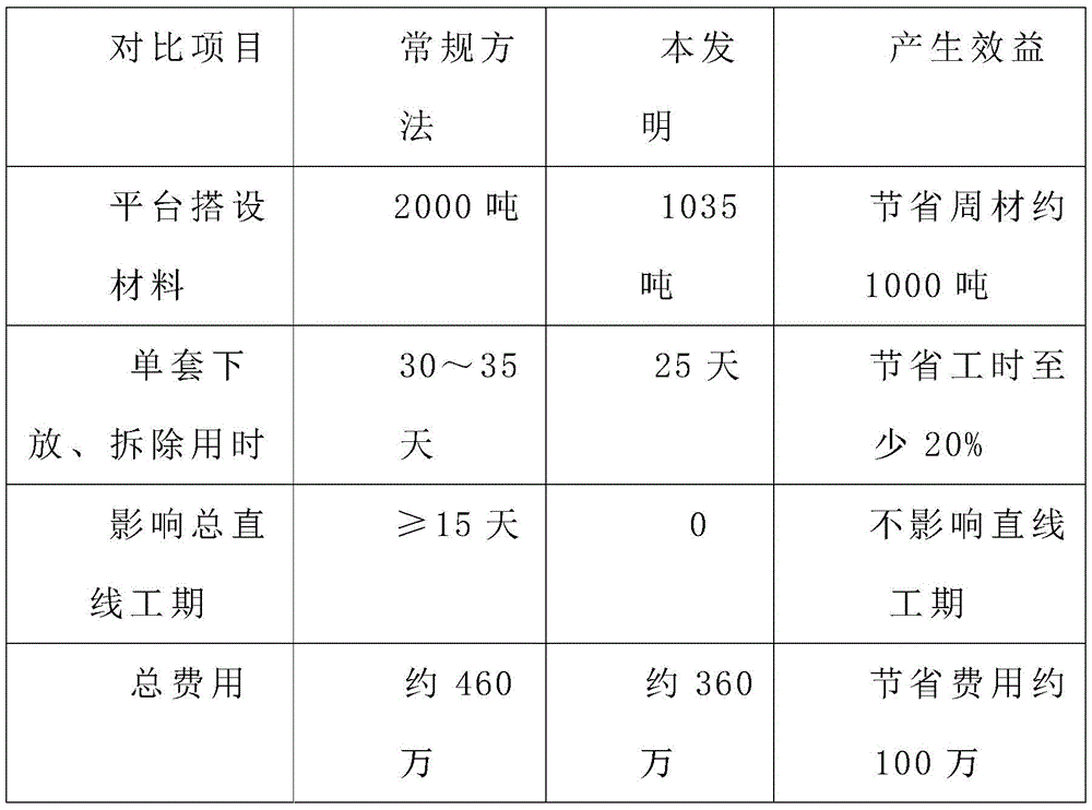
The lowering and dismantling of the movable formwork is a major difficulty in the construction of the cast-in-place beam movable formwork method. The closure section of the cast-in-place beam is positioned in a shallow beach area, the clearance for dismantling the formwork is small, the difficulty is high, and the dismantling of the movable formwork at home and abroad is not precedent. The idea of bridge rotation construction and incremental launching construction is applied to the movable formwork for the first time, and the original complex and troublesome things are convenient and fast. The invention can be used for lowering and dismantling the movable formwork with more movable formwork sleeves, small construction interval between adjacent movable formworks, shallow beach area and small clearance, is also suitable for lowering and dismantling the conventional formwork and dismantling a large-scale support, and provides economic, reliable and practical construction technical experience for similar projects in the future.
The above description is only a preferred embodiment of the present invention, and the scope of the present invention should not be limited thereby, and all the simple equivalent changes and modifications made in the claims and the description of the present invention are within the scope of the present invention.
Claims (8)
1. A construction method for lowering and dismantling a movable formwork based on convenience is characterized in that a movable formwork longitudinal and transverse moving system is applied to a formwork dismantling process, and a main member of the formwork is dismantled conveniently, and the construction method comprises the following steps:
arranging a trolley, a transverse moving track and a temporary support pad on a platform to form a movable mould frame longitudinal and transverse moving system;
step two, after the movable mold frame moves to the tail span, the 2 nd group and the penultimate group of bottom mold trusses are not turned back, and A, B sections of the bottom mold trusses are connected by I-shaped steel during mold closing;
step three, gradually burying the formwork to lower the preformed holes and prevent the precision rolled steel for overturn before pouring concrete of the last two holes of the single formwork; after the tail span concrete is poured, the bearing beam base is poured with C50 concrete to form a leveling block;
step four, the bearing beam is firstly installed and directly hoisted on the bridge floor by a large truck crane and is accurately positioned;
step five, after longitudinal and transverse prestress tensioning of the cast-in-place beam is finished, the die carrier is dropped and integrally longitudinally moved for retreating by 1.5-2 meters, steel stranded wires are used for connecting the bearing beam and the anchoring points at the top of the main beam of the die carrier, and each steel stranded wire is pre-tightened;
after the lifting point is tested to be stressed correctly by lifting, fixing the tail part of the bracket at one side on a main beam of a die set by a chain block, stabilizing the tail part of the bracket at the other side by a track sling force, then removing the bracket, carrying out finish rolling, finally lifting the bracket with the track sling force by a truck crane and a track crane, transversely moving the bracket by 70-100 cm to form a reserved hole, then putting the bracket on a bearing platform, removing the rest brackets, putting the rest brackets down according to the steps, and after the main member is removed, lifting the bracket to the platform and disassembling and rotating the bracket;
operating the hydraulic pump station of the integral lowering system to synchronously and slowly lower the whole set of the movable mould frame to a trolley which is arranged on the platform in advance;
step eight, putting the die frame in place, and firstly removing the outer die system, the girder top I-steel and the like; then pulling a transverse moving steel strand by a trolley on the side of the trestle to transversely move for 0.3-1 m to open the die, and removing the whole bottom die truss group;
pushing and longitudinally moving six sections of main beams on one side through a longitudinally moving oil cylinder on the trolley, and removing a third joint after the front three sections of main beams are in a transverse moving space; and then repeatedly pulling and anchoring steel strands at the end parts of the transverse moving tracks by using a transverse moving oil cylinder on the trolley to transversely move the front three main beams out of the bottom of the cast-in-place beam or the bottom of the adjacent movable mould frame, finally dismantling the main beams by using a gantry crane or a crawler crane, and moving out and dismantling the other main beams by adopting the same method.
2. The convenient moving formwork lowering and dismantling construction method as claimed in claim 1, wherein in the first step, two lateral moving rails on two sides are symmetrically arranged right above a beret beam, the lateral moving rails and temporary support pads are required to be based on the highest point of a platform, the lower portion of the platform is raised, the rails are kept horizontal, deviation is controlled within a range of +/-5 mm, stainless steel strips need to be attached to the surfaces of the rails, lubricating grease is smoothly coated on the rails by polishing, the lateral moving rails are required to be smooth, and the end reaction beams of the lateral moving rails need to be welded firmly.
3. The convenient movable formwork lowering and dismantling construction method according to claim 1, characterized in that in the fourth step, the same-width bearing beam is transferred and installed in the following steps: and after the previous die set lowering system is disassembled, rotating the bearing beam by 90 degrees by using a rotating base, then hoisting to an installation position by using a gantry crane, centering and positioning, and then rotating until the center of a hoisting point hole is aligned with the center of a lowering hole position.
4. The convenient-based mobile formwork lowering and dismantling construction method according to claim 1, characterized in that in the fourth step, the different-width bearing beam transfer installation step is as follows: firstly, the bearing beam is lifted and hoisted to the position near the installation position by a gantry crane, then the bearing beam is moved to the right by a chain block, and after the bearing beam rotates by 90 degrees, the bearing beam is accurately positioned by a crawler crane and the gantry crane.
5. The convenient moving formwork lowering and dismantling construction method according to claim 1 is characterized in that in the fourth step, after the bearing beam is leveled and installed in place, gaps among the bottom support pad, the leveling block and the bridge floor are filled and compacted with support grouting materials, and good contact of a stress surface is ensured.
6. The convenient movable formwork lowering and dismantling construction method based on the claim 5 is characterized in that in the fourth step, the same grouting material for the cast-in-place beam support is adopted as the support grouting material, the water-material ratio is strictly controlled according to material design, the strength of the filling material is guaranteed to be not lower than that of C50 concrete, and then two groups of anti-overturn finish rolled steel are installed on the inner side of the bearing beam support pad.
7. The convenient movable formwork lowering and dismantling construction method based on the claim 1 is characterized in that in the fifth step, after formwork lowering preparation work is completed, firstly, the formwork is tried to be lifted and stabilized for 30 min; and (4) after checking that all stress points are normal, the jack has no obvious pressure relief, the concrete cushion seat under the supporting cushion of the carrier beam has no crushing phenomenon, and the fine rolled steel has no looseness, continuing to stabilize the pressure for 12 hours, and after checking that all the stress points have no obvious abnormality, performing the next procedure.
8. The convenient movable formwork lowering and dismantling construction method according to claim 1, characterized in that in the seventh step, synchronous balance precision is maintained within a range of +/-10 mm through a hydraulic control system; the lowering process is also carried out by observing the accumulated descending height of each lifting point through a measuring rope; the measuring rope is arranged on the side edge of a wing plate of the main beam corresponding to the lifting point, the lowering speed is slowed to 0.5m/h when the die carrier is 0.5m away from a trolley sliding plate, the lowering is suspended when the die carrier is 2cm away from the trolley sliding plate, whether gaps of the trolleys are consistent or not is checked, then the I-steel of the pushing auxiliary pier is tightly pushed against the bottom of the main beam, and finally the die carrier is completely lowered to be supported by the trolley on the platform and the pushing auxiliary pier.
Priority Applications (1)
| Application Number | Priority Date | Filing Date | Title |
|---|---|---|---|
| CN202010215150.XA CN111395176A (en) | 2020-03-24 | 2020-03-24 | Construction method for lowering and dismantling movable formwork based on convenience |
Applications Claiming Priority (1)
| Application Number | Priority Date | Filing Date | Title |
|---|---|---|---|
| CN202010215150.XA CN111395176A (en) | 2020-03-24 | 2020-03-24 | Construction method for lowering and dismantling movable formwork based on convenience |
Publications (1)
| Publication Number | Publication Date |
|---|---|
| CN111395176A true CN111395176A (en) | 2020-07-10 |
Family
ID=71427443
Family Applications (1)
| Application Number | Title | Priority Date | Filing Date |
|---|---|---|---|
| CN202010215150.XA Pending CN111395176A (en) | 2020-03-24 | 2020-03-24 | Construction method for lowering and dismantling movable formwork based on convenience |
Country Status (1)
| Country | Link |
|---|---|
| CN (1) | CN111395176A (en) |
Cited By (2)
| Publication number | Priority date | Publication date | Assignee | Title |
|---|---|---|---|---|
| CN112610014A (en) * | 2020-12-07 | 2021-04-06 | 中铁建工集团有限公司 | Sliding structure for railway passenger station reconstruction and extension project and construction method thereof |
| CN112695650A (en) * | 2020-12-24 | 2021-04-23 | 保利长大工程有限公司 | Downward movable formwork method construction method for shoal variable-curve wide cast-in-place beam |
-
2020
- 2020-03-24 CN CN202010215150.XA patent/CN111395176A/en active Pending
Cited By (2)
| Publication number | Priority date | Publication date | Assignee | Title |
|---|---|---|---|---|
| CN112610014A (en) * | 2020-12-07 | 2021-04-06 | 中铁建工集团有限公司 | Sliding structure for railway passenger station reconstruction and extension project and construction method thereof |
| CN112695650A (en) * | 2020-12-24 | 2021-04-23 | 保利长大工程有限公司 | Downward movable formwork method construction method for shoal variable-curve wide cast-in-place beam |
Similar Documents
| Publication | Publication Date | Title |
|---|---|---|
| CN208815424U (en) | A kind of bridge descending hanging basket | |
| CN111794119B (en) | Temporary supporting system and hoisting method for basket type steel box tie bar arch | |
| CN106930541A (en) | A kind of construction method of suspension type steel vestibule | |
| CN111139749A (en) | Large-span bearing type continuous steel truss girder cantilever erection construction method | |
| CN111188276A (en) | Segmental beam sliding and assembling construction method | |
| CN113047447B (en) | Split-level steel structure building semi-reverse construction method | |
| CN112458918A (en) | High-pier hydraulic jacking integral steel frame platform formwork turnover construction system and construction method | |
| CN111395176A (en) | Construction method for lowering and dismantling movable formwork based on convenience | |
| CN111455852A (en) | Assembling method of movable formwork for bridge construction | |
| CN112854008A (en) | Prefabricated bridge pier and beam integrated bridge girder erection machine and construction method thereof | |
| CN202064281U (en) | Slip form frame | |
| CN110438908B (en) | Deck-type box-type arch bridge reconstruction construction method | |
| CN205529915U (en) | Ladder type masts type hangs pieces together loop wheel machine | |
| CN218434629U (en) | Lifting frame for tower type pier construction | |
| CN111576227A (en) | Construction method of main arch and auxiliary arch of double-flying-wing arch bridge and lifting appliance used by same | |
| CN111519545A (en) | Pier and capping beam integrated construction platform and construction method thereof | |
| CN216892057U (en) | Large-span steel-concrete composite beam bridge steel box girder section floats and holds in palm top and pushes away construction system | |
| CN115961549A (en) | Rear-feeding beam type erection construction method for large-tonnage whole-section steel beam of cable-stayed bridge | |
| CN102493363A (en) | Quick construction method for segment No.0 of continuous beam | |
| CN115305835A (en) | Construction method for erecting double-section whole-section steel truss girder by using girder erection crane | |
| CN212335771U (en) | Descending movable formwork demolishs auxiliary device based on it is convenient | |
| CN111139742B (en) | Method for mounting and dismounting highway bridge girder erection machine | |
| CN110438906B (en) | Arch rib construction method for deck box type arch bridge | |
| CN110438907B (en) | Deck type arch bridge construction method based on steel arch frame | |
| CN210368664U (en) | Wide-body bridge girder erection machine |
Legal Events
| Date | Code | Title | Description |
|---|---|---|---|
| PB01 | Publication | ||
| PB01 | Publication | ||
| SE01 | Entry into force of request for substantive examination | ||
| SE01 | Entry into force of request for substantive examination |