CN111356830B - Throttling device and fuel evaporation gas recovery system - Google Patents
Throttling device and fuel evaporation gas recovery system Download PDFInfo
- Publication number
- CN111356830B CN111356830B CN201880073856.8A CN201880073856A CN111356830B CN 111356830 B CN111356830 B CN 111356830B CN 201880073856 A CN201880073856 A CN 201880073856A CN 111356830 B CN111356830 B CN 111356830B
- Authority
- CN
- China
- Prior art keywords
- passage
- valve
- regulating valve
- regulating
- gas
- Prior art date
- Legal status (The legal status is an assumption and is not a legal conclusion. Google has not performed a legal analysis and makes no representation as to the accuracy of the status listed.)
- Active
Links
Images


Classifications
-
- F—MECHANICAL ENGINEERING; LIGHTING; HEATING; WEAPONS; BLASTING
- F02—COMBUSTION ENGINES; HOT-GAS OR COMBUSTION-PRODUCT ENGINE PLANTS
- F02D—CONTROLLING COMBUSTION ENGINES
- F02D9/00—Controlling engines by throttling air or fuel-and-air induction conduits or exhaust conduits
- F02D9/02—Controlling engines by throttling air or fuel-and-air induction conduits or exhaust conduits concerning induction conduits
-
- F—MECHANICAL ENGINEERING; LIGHTING; HEATING; WEAPONS; BLASTING
- F02—COMBUSTION ENGINES; HOT-GAS OR COMBUSTION-PRODUCT ENGINE PLANTS
- F02M—SUPPLYING COMBUSTION ENGINES IN GENERAL WITH COMBUSTIBLE MIXTURES OR CONSTITUENTS THEREOF
- F02M25/00—Engine-pertinent apparatus for adding non-fuel substances or small quantities of secondary fuel to combustion-air, main fuel or fuel-air mixture
- F02M25/08—Engine-pertinent apparatus for adding non-fuel substances or small quantities of secondary fuel to combustion-air, main fuel or fuel-air mixture adding fuel vapours drawn from engine fuel reservoir
-
- F—MECHANICAL ENGINEERING; LIGHTING; HEATING; WEAPONS; BLASTING
- F02—COMBUSTION ENGINES; HOT-GAS OR COMBUSTION-PRODUCT ENGINE PLANTS
- F02M—SUPPLYING COMBUSTION ENGINES IN GENERAL WITH COMBUSTIBLE MIXTURES OR CONSTITUENTS THEREOF
- F02M69/00—Low-pressure fuel-injection apparatus ; Apparatus with both continuous and intermittent injection; Apparatus injecting different types of fuel
- F02M69/30—Low-pressure fuel-injection apparatus ; Apparatus with both continuous and intermittent injection; Apparatus injecting different types of fuel characterised by means for facilitating the starting-up or idling of engines or by means for enriching fuel charge, e.g. below operational temperatures or upon high power demand of engines
- F02M69/32—Low-pressure fuel-injection apparatus ; Apparatus with both continuous and intermittent injection; Apparatus injecting different types of fuel characterised by means for facilitating the starting-up or idling of engines or by means for enriching fuel charge, e.g. below operational temperatures or upon high power demand of engines with an air by-pass around the air throttle valve or with an auxiliary air passage, e.g. with a variably controlled valve therein
-
- Y—GENERAL TAGGING OF NEW TECHNOLOGICAL DEVELOPMENTS; GENERAL TAGGING OF CROSS-SECTIONAL TECHNOLOGIES SPANNING OVER SEVERAL SECTIONS OF THE IPC; TECHNICAL SUBJECTS COVERED BY FORMER USPC CROSS-REFERENCE ART COLLECTIONS [XRACs] AND DIGESTS
- Y02—TECHNOLOGIES OR APPLICATIONS FOR MITIGATION OR ADAPTATION AGAINST CLIMATE CHANGE
- Y02T—CLIMATE CHANGE MITIGATION TECHNOLOGIES RELATED TO TRANSPORTATION
- Y02T10/00—Road transport of goods or passengers
- Y02T10/10—Internal combustion engine [ICE] based vehicles
- Y02T10/12—Improving ICE efficiencies
Landscapes
- Engineering & Computer Science (AREA)
- Chemical & Material Sciences (AREA)
- Combustion & Propulsion (AREA)
- Mechanical Engineering (AREA)
- General Engineering & Computer Science (AREA)
- Supplying Secondary Fuel Or The Like To Fuel, Air Or Fuel-Air Mixtures (AREA)
- Control Of Throttle Valves Provided In The Intake System Or In The Exhaust System (AREA)
Abstract
The invention provides a throttling device and a fuel evaporation gas recovery system, wherein the throttling device comprises: a throttle valve (30) that opens and closes the main passage (12); a main body (10) having a main passage (12), a sub-passage (14) bypassing the throttle valve (30), and gas passages (15, 14b) for introducing fuel evaporation gas into the main passage (12); a first adjustment valve (41) that adjusts the passage area of the sub-passage (14); a drive source (50) for driving the first adjustment valve (41); and a second regulating valve (61) for regulating the passage area of the gas passage (15); the second regulating valve (61) is driven by the driving force of the driving source (50). Accordingly, the increase of dedicated parts can be suppressed, the cost can be reduced, the size can be reduced, and the fuel evaporation gas can be reliably recovered without being released to the outside.
Description
Technical Field
The present invention relates to a throttle device and a fuel vapor recovery system including a structure for introducing a fuel vapor in a fuel tank of a motorcycle or the like into an intake system of an engine.
Background
In a conventional vehicle such as a motorcycle, in order to prevent evaporative gas of fuel generated in a fuel tank from being released into the atmosphere, there is known an evaporative fuel treatment apparatus provided with a canister (canister) that temporarily stores the evaporative gas, a charging pipe that guides the evaporative gas from the fuel tank to the canister, and a discharge pipe that guides the evaporative gas from the canister to an intake passage of an engine, and the evaporative gas in the canister is discharged into the intake passage by a negative pressure generated in the intake passage (see, for example, patent document 1 and patent document 2).
However, in the evaporated fuel processing apparatus, since the amount of the evaporated gas discharged from the canister into the intake passage depends on the negative pressure of the intake passage, it is difficult to arbitrarily control the amount of the evaporated gas, and the passage area of the exhaust pipe must be set in accordance with the demand for the amount of the evaporated gas for each vehicle.
In other motorcycles and the like, in order to prevent the evaporated gas of the fuel generated in the fuel tank from being released into the atmosphere, there has been known a canister arrangement structure or a fuel evaporated gas recovery apparatus provided with a canister for temporarily storing the evaporated gas, a charging pipe for guiding the evaporated gas from the fuel tank to the canister, an exhaust pipe for guiding the evaporated gas from the canister to an intake passage of an engine, and an exhaust valve including a dedicated drive source on a downstream side of the canister or in a middle of the exhaust pipe, wherein the evaporated gas in the canister is exhausted into the intake passage at a desired flow rate by appropriately controlling the exhaust valve (for example, see patent documents 3 and 4)
However, the metal can arrangement structure and the fuel vapor recovery device require an exhaust valve including a dedicated drive source, and particularly in a small-sized motorcycle where cost reduction is desired, increase in parts, increase in cost, and increase in size are not preferable.
Documents of the prior art
Patent document
Patent document 1: japanese patent laid-open publication No. 2013-71486
Patent document 2: japanese patent laid-open publication No. 2013-19398
Patent document 3: japanese patent laid-open No. 2012-7537
Patent document 4: japanese patent laid-open No. 2016-8014
Disclosure of Invention
Problems to be solved by the invention
The present invention has been made in view of the above circumstances, and an object thereof is to provide a throttle device and a fuel vapor recovery system capable of recovering fuel vapor while suppressing an increase in dedicated parts, reducing cost, reducing size, and the like.
Means for solving the problems
The throttle device of the present invention comprises: a throttle valve that opens and closes the main passage; a main body having a main passage, a sub-passage bypassing the throttle valve, and a gas passage introducing the fuel evaporation gas into the main passage; a first regulating valve for regulating the passage area of the auxiliary passage; a drive source for driving the first regulating valve; and a second regulating valve that is driven by the driving force of the driving source to regulate the passage area of the gas passage.
In the above-described throttle device, the following configuration may be adopted: the first regulating valve is disposed to be movable back and forth in a predetermined direction, and the second regulating valve is disposed to be driven to open and close in conjunction with the movement of the first regulating valve.
In the above-described throttle device, the following configuration may be adopted: the first and second regulating valves are arranged such that when the first regulating valve moves in the valve closing direction, the second regulating valve moves in the valve opening direction.
In the above-described throttle device, the following configuration may be adopted: the second regulating valve is maintained in a state of contact with the first regulating valve by a biasing force of the second biasing spring when the second regulating valve is driven to open and close.
In the above-described throttle device, the following configuration may be adopted: the first regulating valve and the second regulating valve are arranged so as not to contact each other when the second regulating valve is maintained in the valve-closed state.
In the above-described throttle device, the following configuration may be adopted: the sub-passage includes an upstream-side passage branching from the main passage, a downstream-side passage merging with the main passage, and a communication passage communicating the upstream-side passage with the downstream-side passage, and the gas passage includes a downstream-side passage forming a part of the sub-passage, and an introduction passage communicating with the downstream-side passage.
In the above-described throttle device, the following configuration may be adopted: the first regulating valve is disposed to be reciprocally movable in a predetermined direction, the second regulating valve is disposed to be driven to open and close in conjunction with the movement of the first regulating valve, the communication passage and the introduction passage are arranged in the predetermined direction, the first regulating valve regulates a passage area of the communication passage, and the second regulating valve regulates a passage area of the introduction passage.
In the above-described throttle device, the following configuration may be adopted: the fuel vapor control valve includes a sleeve (casting) detachably coupled to a main body, housing a second control valve, and defining a passage communicating with a gas passage, the sleeve including a connector to which a pipe through which the fuel vapor flows can be connected.
The fuel vapor recovery system according to the present invention is a fuel vapor recovery system for recovering fuel vapor to an intake system of an engine, and includes: a throttle device mounted on an engine and including the sleeve; a fuel tank; a canister for temporarily storing fuel vapor introduced into the fuel tank; and a pipe connecting a connector of the sleeve included in the throttle device to the metal can.
In the fuel vapor recovery system, the following configuration may be adopted: the second adjustment valve is driven to open and close by drive control of a drive source based on information on the opening degree of a throttle valve included in the throttle device.
ADVANTAGEOUS EFFECTS OF INVENTION
According to the throttle device and the fuel vapor recovery system having the above-described configuration, the fuel vapor can be reliably recovered without being released to the outside, while suppressing an increase in the number of dedicated parts and reducing the cost and size.
Drawings
Fig. 1 is a system diagram showing a fuel vapor recovery system of an engine including a throttle device of the present invention.
Fig. 2 is an external perspective view showing an embodiment of the throttle device of the present invention.
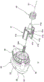
Fig. 3 is an exploded perspective view of the throttle device shown in fig. 2.
Fig. 4 is a partially cut-away perspective view of a portion of the throttle device shown in fig. 2.
Fig. 5 is a partially cut-away perspective view of a portion of the throttle device shown in fig. 2.
Fig. 6 is a sectional view through the axis of the main passage of the throttle device shown in fig. 2.
Fig. 7 is an exploded perspective view showing a drive source, a first adjustment valve, and a first biasing spring included in the throttle device of the present invention.
Fig. 8 is an exploded perspective view showing a second regulating valve, a second biasing spring, and a sleeve included in the throttle device of the present invention.
Fig. 9 is a perspective cross-sectional view showing a state in which the second regulating valve and the second biasing spring are accommodated in the sleeve.
Fig. 10 is a partial cross-sectional view illustrating operations of the first regulating valve and the second regulating valve included in the throttling device according to the present invention, the partial cross-sectional view showing a state in which the second regulating valve is closed.
Fig. 11 is a partial cross-sectional view illustrating operations of the first regulating valve and the second regulating valve included in the throttle device according to the present invention, the partial cross-sectional view showing a state in which the second regulating valve is opened.
Fig. 12 is a partial cross-sectional view showing another embodiment of a first regulating valve included in the throttle device of the present invention.
Fig. 13 is a characteristic diagram showing operation characteristics of the first and second adjustment valves of the embodiment shown in fig. 12.
Fig. 14 is a partial cross-sectional view showing another embodiment in which a sleeve, a first regulating valve, and a second regulating valve are modified in the throttle device shown in fig. 12.
Fig. 15 is a partial sectional view showing a modification of the embodiment shown in fig. 11.
[ description of symbols ]
1: throttle device
2: engine
3: air intake system
6: fuel tank
7: metal can
8 b: piping
10: main body
12: main channel
14: secondary channel
14 a: upstream side channel (auxiliary channel)
14 b: downstream side passage (auxiliary passage, gas passage)
S1: axis (prescribed direction)
14 c: connecting channel (auxiliary channel)
15: introduction channel (gas channel)
30: throttle valve
41. 43, 44: first regulating valve
42: a first force application spring
50: driving source
61. 63: second regulating valve
62. 64: second force application spring
70. 170: sleeve pipe
71. 171: channel
74: connector with a locking member
Detailed Description
An embodiment of the present invention will be described below with reference to fig. 1 to 11.
As shown in fig. 1, a throttle device 1 according to an embodiment is incorporated in an intake system 3 mounted on an engine 2 of a motorcycle, and is incorporated in the middle of an intake pipe 3b on the downstream side of an air cleaner 3 a.
Here, the throttle device 1 is equipped with a rotation drive source 4 for rotationally driving the valve shaft 20 of the throttle valve 30, and a position sensor 5 for detecting the opening position of the throttle valve 30.
The motorcycle includes, in addition to an engine 2 including an injector 2a for fuel injection and an intake system 3: a fuel tank 6, a canister 7, a pipe 8a connecting the fuel tank 6 and the canister 7, a pipe 8b connecting the canister 7 and a connector 74 of the throttle device 1, and a control unit 9.
The metal can 7 includes: a container 7a, an introduction connector 7b, an outlet connector 7c, and a suction tube 7 d.
The container 7a contains activated carbon that temporarily adsorbs fuel vapor.
The introduction connector 7b is connected to a pipe 8a for introducing the fuel vapor from the fuel tank 6.
The lead-out connector 7c is connected to a pipe 8b that guides the fuel vapor stored in the container 7a to the throttle device 1.
The suction pipe 7d takes in outside air in accordance with the pressure in the container 7a, and a filter and a check valve are disposed inside thereof.
The intake pipe 7d is not open to the outside air, and may be connected to the downstream side of the air cleaner 3a via a pipe.
That is, the throttle device 1, the fuel tank 6, the canister 7, the pipe 8a connecting the fuel tank 6 and the canister 7, and the pipe 8b connecting the connector 74 of the throttle device 1 and the canister 7 constitute a fuel vapor recovery system for recovering fuel vapor to the intake system 3 of the engine 2. The pipe 8a may be omitted, and the canister 7 and the fuel tank 6 may be disposed adjacent to each other.
As shown in fig. 2 to 4, the throttle device 1 includes: the valve includes a body 10, a valve shaft 20 having an axis S, a throttle valve 30, a first regulating valve 41, a first biasing spring 42, a drive source 50 for driving the first regulating valve 41, a second regulating valve 61, a second biasing spring 62, and a sleeve (casting) 70 that houses the second regulating valve 61 and the second biasing spring 62 and is coupled to the body 10.
The main body 10 is formed of a metal material such as aluminum, and includes: the connection flange portion 11a, the connection flange portion 11b, the main passage 12, the valve shaft hole 13 through which the valve shaft 20 passes, the sub passage 14, the introduction passage 15 forming a part of the gas passage through which the fuel evaporation gas is introduced, the recess portion 16 that houses the first adjustment valve 41 and the first biasing spring 42, the mounting portion 17 to which the drive source 50 is mounted, and the flange portion 18 to which the sleeve 70 is mounted.
The connecting flange portions 11a and 11b are connected to the middle of the intake pipe 3b such that the main passage 12 defines a part of an intake passage of the intake system 3.
Here, the connection flange portion 11a is connected to the upstream side, and the connection flange portion 11b is connected to the downstream side.
The main passage 12 is formed in a cylindrical shape elongated in the direction of the axis L to flow intake air as a fluid.
The valve shaft hole 13 is formed as a circular hole so that the valve shaft 20 can be freely rotatably inserted therethrough.
The valve shaft 20 may be supported via a bearing fitted in the valve shaft hole 13.
The sub-passage 14 is formed in the following manner: the flow branches off from the main passage 12 so as to bypass the throttle valve 30, and then merges with the main passage 12 again.
Here, as shown in fig. 4 and 5, the sub-passage 14 is formed by an upstream passage 14a branched from the main passage 12, a downstream passage 14b merged with the main passage 12, and a communication passage 14c communicating the upstream passage 14a and the downstream passage 14 b.
The upstream side passage 14a is formed in a circular cross section, and is branched from the main passage 12 on the upstream side of the throttle valve 30 and then obliquely extended.
The downstream passage 14b has a circular cross section and is formed on the downstream side of the throttle valve 30 so as to extend obliquely toward the main passage 12 and merge with the main passage.
The communication passage 14c is circular in cross section, and is formed so as to extend in the direction of the axis S1, which is a predetermined direction, while communicating the upstream passage 14a and the downstream passage 14 b.
Here, the axis S1 is arranged parallel to the axis S of the valve shaft 20.
The introduction passage 15 forms a part of a gas passage through which the fuel evaporation gas is introduced, is circular in cross section, is formed so as to extend in the direction of the axis S1, and communicates with the passage 71 of the sleeve 70.
A valve seat 15a on which the second regulating valve 61 is seated is formed on the upstream side of the introduction passage 15.
That is, the introduction passage 15 is aligned on the same axis as the communication passage 14c in the direction of the axis S1.
Therefore, when the body 10 is machined by using a tool such as a drill to machine the introduction passage 15 and the communication passage 14c, the machining can be performed only from the direction of the axis S1, and therefore, the number of steps involved in the machining can be reduced, and the manufacturing cost can be reduced.
In the case where the valve shaft hole 13 is formed by drilling in the same manner as in the case of the main body 10, since the axis S1 is parallel to the axis S, the valve shaft hole 13, the introduction passage 15, and the communication passage 14c can be machined by simply moving the main body 10 in parallel, and the manufacturing cost can be reduced by reducing the number of steps in the same manner as described above.
In the above configuration, the gas passage for introducing the fuel evaporation gas into the main passage 12 is formed in the main body 10 by the introduction passage 15 and the downstream side passage 14b forming a part of the sub passage 14.
That is, the downstream side passage 14b as a part of the sub-passage 14 doubles as a gas passage.
Therefore, the position where the gas passage opens in the main passage 12 is the position where the downstream side passage 14b of the sub-passage 14 opens, and the structure can be simplified as compared with the case where a dedicated passage is provided as the gas passage.
As shown in fig. 4 to 6, the concave portion 16 is formed as follows: the first regulating valve 41 and the first biasing spring 42 are extended in the direction of the axis S1, and have a substantially elliptical cross section so as to define two contact surfaces 16a without rotating the first regulating valve 41 around the axis S1.
The concave portion 16 is formed so as to communicate with the upstream side passage 14a and the communication passage 14c of the sub-passage 14, and also functions as a part of the upstream side passage or the communication passage.
As shown in fig. 3 and 4, the mounting portion 17 includes: a fitting portion 17a for fitting the joint portion 54 of the drive source 50, and a screw hole 17b into which a screw b1 for fastening the pressing member 56 pressing the joint portion 54 is screwed.
The flange portion 18 includes: an engaging surface 18a for engaging the sleeve 70, and a screw hole 18b into which a screw b2 for fastening the sleeve 70 is screwed.
As shown in fig. 3, the valve shaft 20 has a circular cross section, is formed by a metal material or the like so as to extend in the axis S direction, and includes a slit 21 into which the throttle valve 30 is fitted and a screw hole 22 in a substantially central region.
The valve shaft 20 is inserted into the valve shaft hole 13 of the body 10, and the throttle valve 30 fitted into the slit 21 is fastened by a screw b3, thereby openably and closably holding the throttle valve 30.
As shown in fig. 3 and 6, the throttle valve 30 is formed in a substantially disk shape by a metal material or the like, and includes a circular hole 31 through which a screw b3 is inserted.
The throttle valve 30 is configured in the following manner: after the valve shaft 20 is inserted into the valve shaft hole 13, it is inserted into the slit 21 and fixed to the valve shaft 20 by the screw b3, thereby opening and closing the main passage 12.
The throttle valve 30 opens the main passage 12 to a desired opening degree in accordance with the rotation of the valve shaft 20.
As shown in fig. 4 to 7, the first adjustment valve 41 includes a distal end portion 41a, a cylindrical portion 41b, an internal thread 41c, a flange portion 41d, and two rotation stop walls 41 e.
In the idling region of the engine 2, the first adjustment valve 41 is appropriately driven by the drive source 50 to adjust the flow rate of the intake air flowing through the sub-passage 14.
The distal end portion 41a is formed in a conical shape extending in the direction of the axis S1, and is disposed so as to face the communication passage 14c and define a metering portion.
Then, the first adjustment valve 41 moves in the direction of the axis S1, whereby the leading end portion 41a adjusts the passage area of the communication passage 14 c.
As shown in fig. 4 and 5, the distal end portion 41a is formed so as to be contactable with the distal end portion 61a of the second adjustment valve 61 in the direction of the axis S1.
The cylindrical portion 41b is formed to extend in the direction of the axis S1 in the direction opposite to the distal end portion 41 a.
The female screw 41c is formed inside the cylindrical portion 41b, and is screwed into the male screw 52a of the drive source 50 over a predetermined stroke.
The flange portion 41d is formed around the cylindrical portion 41b and receives one end portion of the first biasing spring 42.
The two rotation preventing walls 41e are formed to extend in the direction of the axis S1 from the outer peripheral region of the flange portion 41d and define a substantially elliptical outer contour.
As shown in fig. 6, the rotation preventing walls 41e contact the contact surfaces 16a of the recess 16 to regulate the rotation of the first adjustment valve 41 about the axis S1, and guide the distal end portion 41a to reciprocate on the axis S1.
The first biasing spring 42 is a compression-type coil spring, and is disposed in the recess 16 such that one end thereof is engaged with the flange portion 41d of the first adjustment valve 41 and the other end thereof is engaged with the bottom wall of the recess 16 and is compressed by a predetermined amount.
The first biasing spring 42 biases the first adjustment valve 41 in the direction of the axis line S1, which is a predetermined direction, that is, in the valve opening direction in which the distal end portion 41a is away from the communication passage 14 c.
This prevents the internal thread 41c of the first adjustment valve 41 and the external thread 52a of the drive source 50 from rattling (loosening) in the direction of the axis S1, and thus the passage area can be adjusted with high accuracy.
Further, a first biasing spring that biases the first regulating valve 41 in the valve closing direction may be used.
As shown in fig. 4 and 7, the drive source 50 includes: a stepping motor 51, an output shaft 52, a housing 53, an engaging portion 54, a connector 55, and a pressing member 56.
The stepping motor 51 operates in synchronization with the pulse power, and includes a rotor coupled with an output shaft 52, a stator disposed around the rotor, and a coil (coil) wound around the stator. As the structure of the coil, two-phase, three-phase, five-phase, and the like can be applied.
The output shaft 52 outputs a rotational force from the stepping motor 51, including a male screw 52a formed in a region on the leading end side.
The male screw 52a is screwed into the female screw 41c of the first adjustment valve 41.
Therefore, the first regulating valve 41 moves in the valve closing direction or the valve opening direction along the axis S1 in accordance with the rotation direction of the output shaft 52.
The housing 53 is formed to house the stepping motor 51 and to isolate the stepping motor 51 from the fluid flowing into the recess 16.
The joint portion 54 is integrally formed in the housing 53, and is engaged with the fitting portion 17a in the mounting portion 17 of the main body 10, and is pressed by the pressing member 56 and fastened by a screw b 1.
The connector 55 has a terminal for supplying electric power to the stepping motor 51, and is electrically connected to a wiring of the motorcycle.
The pressing member 56 is disposed so as to press the engaging portion 54 from the outside after the engaging portion 54 is fitted to the fitting portion 17a of the main body 10, and is fastened to the main body 10 by a screw b 1.
The second adjustment valve 61 is formed using a metal material so as to extend in the direction of the axis S1, and includes, as shown in fig. 4, 5, and 8: the tip portion 61a, the columnar portion 61b, the conical surface 61c, the flange portion 61d, the groove portion 61e, and the groove portion 61 f.
The second regulating valve 61 regulates the flow rate of the evaporated fuel gas flowing through the introduction passage 15, which is a gas passage, in an operation region other than the idling region of the engine 2 by the driving force of the driving source 50 transmitted via the first regulating valve 41.
The distal end portion 61a is formed in a cylindrical shape and is disposed so as to pass through the introduction passage 15 and face the inside of the downstream side passage 14 b.
The distal end portion 61a is formed so as to be contactable with the distal end portion 41a of the first adjustment valve 41 by the biasing force of the second biasing spring 62.
Here, the distal end portion 61a is disposed so as not to contact the distal end portion 41a of the first adjustment valve 41 when the second adjustment valve 61 is in the valve-closed state.
As shown in fig. 8 and 9, the columnar portion 61b is inserted into the guide passage 71c of the sleeve 70 and is guided movably in the direction of the axis S1.
The conical surface 61c is in close contact with a valve seat 15a formed at the edge of the introduction passage 15 in the valve-closed state. Further, the conical surface 61c adjusts the passage area of the introduction passage 15 by appropriately moving the second adjustment valve 61 in the direction of the axis S1.
The flange portion 61d is inserted into the guide passage 71b of the sleeve 70 and is guided to be movable in the direction of the axis S1.
The grooves 61e and 61f are formed to form a gap with the inner wall surfaces of the guide passage 71b and the guide passage 71c of the sleeve 70 so that the fuel evaporation gas introduced through the pipe 8b flows toward the introduction passage 15.
The second biasing spring 62 is a compression-type coil spring, and is disposed in the passage 71 of the sleeve 70 such that one end thereof is engaged with the flange portion 61d of the second adjustment valve 61 and the other end thereof is engaged with the receiving surface 72 of the sleeve 70 and is compressed by a predetermined amount.
The second biasing spring 62 biases the second regulating valve 61 in the valve closing direction. That is, the force is applied in a direction in which the distal end portion 61a contacts the distal end portion 41a of the first adjustment valve 41.
According to the above-described arrangement relationship of the first and second adjustment valves 41 and 61, when the second adjustment valve 61 is driven to open and close, the second adjustment valve 61 is maintained in a state of being in contact with the first adjustment valve 41 by the second biasing spring 62.
This allows the second adjustment valve 61 to be interlocked with the movement of the first adjustment valve 41.
When the first regulating valve 41 moves in the valve closing direction, the second regulating valve 61 moves in the valve opening direction.
Accordingly, when the second regulating valve 61 is opened and the fuel evaporation gas flows from the introduction passage 15 into the downstream passage 14b, the first regulating valve 41 moves in the valve closing direction, and therefore the fuel evaporation gas can be prevented or suppressed from flowing through the communication passage 14c and flowing into the concave portion 16.
Further, the first adjustment valve 41 and the second adjustment valve 61 are arranged so as not to contact each other when the second adjustment valve 61 is maintained in the valve-closed state.
Accordingly, the closed state of the second adjustment valve 61 can be reliably maintained, and inflow of the fuel evaporation gas outside the desired operation region can be prevented.
According to the above configuration, when the first adjustment valve 41 is driven by the drive source 50, the second adjustment valve 61 is driven to open and close in conjunction with the movement of the first adjustment valve 41, that is, by the drive force of the drive source 50.
In this way, since the drive source 50 for driving the first adjustment valve 41 is also used as the drive source for driving the second adjustment valve 61, a dedicated drive source for the second adjustment valve 61 is not required, and an increase in the number of dedicated parts can be suppressed, thereby achieving cost reduction, size reduction, and the like.
The sleeve 70 is formed using a metal material or the like, and as shown in fig. 8 and 9, includes: channel 71, receiving surface 72, flange 73, connector 74.
The passage 71 is formed by a large-diameter passage 71a, a guide passage 71b, a guide passage 71c, and a small-diameter passage 71d which are arranged in this order with the axis S1 as the center.
The passage 71 communicates with the introduction passage 15 and the downstream side passage 14b, which are gas passages of the main body 10.
The large diameter passage 71a, the guide passage 71b, and the guide passage 71c also function to accommodate the second adjustment valve 61 and the second biasing spring 62.
The flange portion 73 includes a joint surface 73a and a through hole 73 b.
The joint surface 73a is joined to the joint surface 18a of the flange portion 18 of the main body 10.
The through hole 73b is formed to allow a screw b2 screwed into the screw hole 18b of the flange portion 18 of the body 10 to pass therethrough.
The connector 74 is formed in a cylindrical shape so as to be connectable to the pipe 8b for guiding the fuel vapor.
That is, the sleeve 70 is detachably coupled to the body 10, houses the second adjustment valve 61, and defines a passage 71 communicating with the introduction passage 15 and the downstream passage 14b as gas passages.
By providing the sleeve 70 that houses the second adjustment valve 61 in this manner, the second adjustment valve 61 can be easily assembled to the body 10, and the second adjustment valve 61 corresponding to the required specification can be appropriately assembled.
In addition, in the case where there is a conventional throttle device including the first adjustment valve 41 and the drive source 50, the throttle device 1 including the second adjustment valve 61 can be easily provided by performing additional processing or the like on a conventional body, and sharing of parts, reduction in the number of parts, reduction in manufacturing cost, and the like can be realized.
Next, the operation of the fuel vapor recovery system including the throttle device 1 will be described with reference to fig. 10 and 11.
Here, the control unit 9 controls the driving of the rotation driving source 4, the driving of the driving source 50, and the like, based on the detection signal of the position sensor 5, the operation information of the engine 2, and other related information.
First, when the engine 2 is in the idle operation region, the throttle valve 30 is in a state in which the main passage 12 has been closed, and the intake air flowing in the main passage 12 is drawn into the main passage 12 again after flowing in the sub passage 14 so as to bypass the throttle valve 30.
In this state, the first regulating valve 41 is appropriately driven by the driving source 50, and the leading end portion 41a adjusts the passage area of the communication passage 14c, thereby maintaining the idling operation of the engine in a stable state.
That is, as shown in fig. 10, in the idle operation region, the position of the first regulating valve 41 in the direction of the axis S1 is appropriately adjusted by the drive source 50 in a state where the first regulating valve 41 is not in contact with the second regulating valve 61, and the passage area of the communication passage 14c is adjusted. Thereby, the amount of intake air flowing in the sub passage 14 is adjusted.
In the idling region, the second regulating valve 61 is not always in contact with the first regulating valve 41, and therefore the driving force of the driving source 50 is not transmitted.
Therefore, the conical surface 61c of the second adjustment valve 61 is in close contact with the valve seat 15a by the biasing force of the second biasing spring 62, and the valve-closed state is maintained.
This prevents the fuel vapor in the metal can 7 from flowing into the introduction passage 15 from the passage 71, and the fuel vapor is blocked.
On the other hand, when the engine 2 is in an operation region other than the idling operation region, the throttle valve 30 is in a predetermined opening range, and the main passage 12 is opened.
Therefore, the intake air flowing through the main passage 12 does not pass through the sub-passage 14, flows through the main passage 12, and is drawn into the engine 2.
At this time, the first adjustment valve 41 is not required to be used in order to adjust the amount of intake air flowing in the sub-passage 14.
Then, the drive source 50 is drive-controlled based on a detection signal of the position sensor 5 so as to open the second regulating valve 61 and introduce the evaporated fuel gas into the intake system 3.
That is, when the driving amount of the driving source 50 is controlled based on the opening degree information of the throttle valve 30 and other operation information, the second regulating valve 61 is appropriately moved in the direction of the axis S1 via the first regulating valve 41 and opened, and the tip end portion 61a adjusts the passage area of the introduction passage 15.
Thereby, the fuel evaporation gas flows through the introduction passage 15 and the downstream side passage 14b as gas passages, and is introduced into the main passage 12.
Specifically, as shown in fig. 11, in an operation region other than the idle operation region, when the first adjustment valve 41 is driven in the valve closing direction by the drive source 50, the tip end portion 41a comes into contact with the tip end portion 61a of the second adjustment valve 61.
When the first adjustment valve 41 is further driven in the valve closing direction, the second adjustment valve 61 moves in the valve opening direction while resisting the biasing force of the second biasing spring 62 in conjunction with the movement amount of the first adjustment valve 41 in the axis S1 direction.
Thereby, the passage area of the introduction passage 15 is appropriately adjusted, and the flow rate of the fuel evaporation gas flowing into the main passage 12 through the introduction passage 15 and the downstream side passage 14b as the gas passages is adjusted.
As described above, the second adjustment valve 61 is driven to open and close by the drive control of the drive source 50 based on the opening degree information of the throttle valve 30 included in the throttle device 1.
As described above, according to the throttle device 1 configured as described above, the drive source 50 is used as the drive source of the second adjustment valve 61, and therefore, it is possible to suppress an increase in the number of dedicated parts, to reduce the cost, to reduce the size, and the like, and to reliably recover the fuel vapor without discharging the fuel vapor to the outside.
Further, since the second regulating valve 61 that is opened and closed by the driving force of the driving source 50 is provided, the fuel vapor gas can be introduced into the main passage 12 at a desired timing, and therefore the position of the opening of the main passage 12 is not limited to the vicinity of the throttle valve 30 or the downstream side, and the gas passage can be set in a wide area including the upstream side.
Fig. 12 is a view showing another embodiment of the throttle device of the present invention, and is the same as the above embodiment except that the first regulating valve 43 in which the tip portion 41a of the first regulating valve 41 is changed is used. Therefore, the same components are denoted by the same reference numerals, and description thereof is omitted.
In this embodiment, the first trim valve 43 includes: a tip end portion 43a, a cylindrical portion 41b, female screws 41c, a flange portion 41d, and two rotation stop walls 41 e.
The front end portion 43a includes: a conical surface 43a1 defining a gap with the inner peripheral surface of the communication passage 14 c; and a cylindrical surface 43a2 formed continuously with the conical surface 43a1 and sliding in close contact with the inner circumferential surface of the communication passage 14 c.
The conical surface 43a1 is used to adjust the passage area of the communication passage 14c to adjust the flow rate of intake air flowing in the sub-passage 14 in the idle operation region.
The cylindrical surface 43a2 is used to open the second regulating valve 61 in an operation region other than the idling operation region to regulate the flow rate of the fuel vapor flowing through the introduction path 15.
That is, in the idle operation region, the position in the direction of the axis S1 is appropriately adjusted by the drive source 50 within the range of the stroke in which the conical surface 43a1 faces the communication passage 14c, while the first adjustment valve 43 is kept out of contact with the second adjustment valve 61, and the passage area is adjusted. Thereby, the amount of intake air flowing in the sub passage 14 is adjusted.
On the other hand, in an operation region other than the idling operation region, when the first adjustment valve 43 is driven in the valve closing direction by the drive source 50, the tip end portion 43a comes into contact with the tip end portion 61a of the second adjustment valve 61 at a timing of transition from the conical surface 43a1 to the cylindrical surface 43a2 or at a timing after the transition.
When the first regulating valve 43 is further driven in the valve closing direction, the second regulating valve 61 moves in the valve opening direction while resisting the biasing force of the second biasing spring 62 in conjunction with the movement amount of the first regulating valve 43 in the axis S1 direction. Thereby, the second regulating valve 61 is opened, the passage area of the introduction passage 15 is appropriately adjusted, and the flow rate of the fuel evaporation gas is adjusted.
According to this embodiment, as shown in fig. 13, in a region where the first adjustment valve 43 does not exert an adjustment effect on the sub-passage 14, only the second adjustment valve 61 may be operated.
This allows the adjustment operation of the first adjustment valve 43 to be completely separated from the adjustment operation of the second adjustment valve 61, thereby providing a play region.
In particular, when the second regulating valve 61 is in the open state, the first regulating valve 43 is in the state in which the communication passage 14c is closed, and therefore the fuel vapor can be reliably prevented from flowing through the communication passage 14c and flowing into the recessed portion 16.
Further, since the first adjustment valve 43 is not seated on the edge of the communication passage 14c, the engagement or the engagement of the female screw 41c and the male screw 52a due to the excessive movement does not occur, and a desired screw feeding function can be maintained.
Fig. 14 is a view of the throttle device shown in fig. 12, in which the sleeve 170 is used instead of the sleeve 70, the first adjustment valve 44 in which the tip end portion 43a of the first adjustment valve 43 is changed, the second adjustment valve 63 is used instead of the second adjustment valve 61, and the second biasing spring 64 is used instead of the second biasing spring 62. The other configurations are the same as those of the above embodiment. Therefore, the same components are denoted by the same reference numerals, and description thereof is omitted.
In this embodiment, the first trim valve 44 includes: a tip portion 44a, a cylindrical portion 41b, female screws 41c, a flange portion 41d, and two rotation stop walls 41 e.
The front end portion 44a includes: a conical surface 44a1 defining a gap with the inner peripheral surface of the communication passage 14 c; a cylindrical surface 44a2 formed continuously with the conical surface 44a1 and sliding in close contact with the inner circumferential surface of the communication passage 14 c; and a rod 44a3 formed on the tip side of the conical surface 44a 1.
The conical surface 44a1 is used to adjust the passage area of the communication passage 14c to adjust the flow rate of intake air flowing in the sub-passage 14 in the idle operation region.
The cylindrical surface 44a2 is used to open the second regulating valve 61 in an operation region other than the idling operation region to regulate the flow rate of the fuel vapor flowing through the introduction path 15.
The lever 44a3 is formed so as to be detachably in contact with the second trim valve 63.
The second regulating valve 63 is formed in a disk shape having a thin plate covering the area of the introduction passage 15, and is disposed swingably around the support shaft 63 a.
The second biasing spring 64 is a coil torsion spring disposed around the support shaft 63a, and rotationally biases the second regulating valve 63 in the valve closing direction.
The sleeve 170 includes: channel 171, flange 73, connector 74.
The passage 171 communicates with the introduction passage 15 and the downstream side passage 14b as gas passages of the main body 10.
The sleeve 170 is detachably coupled to the main body 10, houses the second adjustment valve 63 and the second biasing spring 64, and defines a passage 171 that communicates with the introduction passage 15 and the downstream passage 14b as gas passages.
That is, in the idle operation region, the position in the direction of the axis S1 is appropriately adjusted by the drive source 50 within the range of the stroke in which the conical surface 44a1 faces the communication passage 14c, while the first adjustment valve 44 is kept out of contact with the second adjustment valve 63, and the passage area is adjusted. Thereby, the amount of intake air flowing in the sub passage 14 is adjusted.
On the other hand, in an operation region other than the idling operation region, when the first adjustment valve 44 is driven in the valve closing direction by the drive source 50, the rod 44a3 comes into contact with the second adjustment valve 63 at a timing of transition from the conical surface 44a1 to the cylindrical surface 44a2 or at a timing after the transition.
When the first regulating valve 44 is further driven in the valve closing direction, the second regulating valve 63 rotates in the valve opening direction while resisting the biasing force of the second biasing spring 64 in conjunction with the movement amount of the first regulating valve 44 in the axis S1 direction. Thereby, the second regulating valve 63 is opened, the passage area of the introduction passage 15 is appropriately adjusted, and the flow rate of the fuel evaporation gas is adjusted.
According to this embodiment, as described above, in the region where the first trim valve 44 does not exert a trimming effect on the sub-passage 14, only the second trim valve 63 can be operated.
This completely separates the adjusting operation of the first adjusting valve 44 from the adjusting operation of the second adjusting valve 63, and thus a play region can be provided.
In particular, when the second regulating valve 63 is in the valve-opened state, the first regulating valve 44 is in a state in which the communication passage 14c is closed, and therefore the fuel vapor can be reliably prevented from flowing through the communication passage 14c and flowing into the recessed portion 16.
Further, since the first adjustment valve 44 is not seated on the edge of the communication passage 14c, the engagement or the engagement of the female screw 41c and the male screw 52a due to the excessive movement does not occur, and a desired screw feeding function can be maintained.
Further, since the second adjustment valve 63 is a thin plate disk and the second biasing spring 64 is a coil torsion spring, the dimension in the direction of the axis S can be reduced, and therefore the sleeve 170 can be made smaller, and the device can be made smaller.
Fig. 15 is a view showing a modification of the embodiment shown in fig. 11.
In this modification, the tip end portion 41a1 in which the inclination angle of the tip end portion 41a of the first adjustment valve 41 or the size of the outer contour is changed is used, compared with the form of the first adjustment valve 41 and the communication passage 14c shown in fig. 11. Further, the inner diameter and shape of the communication passage 14c may be appropriately changed.
As shown in fig. 15, in a region other than the idling operation in which the second adjustment valve 61 is in the valve-opened state, a part of the intake air flowing through the main passage 12 flows through the communication passage 14c and flows into the downstream passage 14 b.
In this way, a part of the intake air introduced from the main passage 12 through the communication passage 14c merges with the fuel evaporation gas introduced through the introduction passage 15, whereby the fuel evaporation gas can be mixed with the intake air in advance.
For example, when the concentration of the fuel vapor introduced from the canister 7 is high, the fuel vapor is diluted with the intake air in advance. Thereby, the fuel evaporation gas can be suppressed or prevented from adhering to the wall surface of the downstream side passage 14 b. Therefore, the fuel evaporation gas can be efficiently introduced into the main passage 12.
In the above-described embodiment, the drive source 50 including the stepping motor is shown as the drive source for driving the first adjustment valve 41, the first adjustment valve 43, and the first adjustment valve 44, but the present invention is not limited to this, and other drive sources including an actuator or drive sources including a Direct Current (DC) motor, a speed reduction mechanism, and the like may be used as long as the first adjustment valve can be driven with high accuracy.
In the above embodiment, the first regulating valve 41, the first regulating valve 43, and the first regulating valve 44 are disposed so as not to contact with the second regulating valve 61 and the second regulating valve 63 when the second regulating valve 61 and the second regulating valve 63 are in the valve-closed state, but the present invention is not limited to this, and may be disposed so as to contact with each other as long as the valve-closed state of the second regulating valve 61 and the second regulating valve 63 is ensured.
In the above embodiment, the first adjustment valve 41, the first adjustment valve 43, and the second adjustment valve 61 are separately formed, but the present invention is not limited to this, and the first adjustment valve and the second adjustment valve may be integrally formed as long as the second adjustment valve is driven to open and close in conjunction with the movement of the first adjustment valve. In this case, the second urging spring may be eliminated.
In the above embodiment, the case where the first biasing spring 42 that biases the first regulating valve 41, the first regulating valve 43, and the first regulating valve 44 in the axis S direction is used has been described, but the present invention is not limited to this, and the first biasing spring may be omitted as long as it is configured so as not to cause rattling, looseness, or the like.
In the above embodiment, the sub-passage 14 including the upstream-side passage 14a, the downstream-side passage 14b, and the communication passage 14c is shown as the sub-passage, but the present invention is not limited to this, and a sub-passage having another form may be adopted as long as the flow rate can be adjusted by the first adjustment valve while bypassing the throttle valve 30.
In the above embodiment, the downstream side passage 14b as a part of the sub passage 14 is used as a gas passage provided in the main body 10, but the present invention is not limited to this, and a dedicated gas passage may be provided.
In the above embodiment, the case where the sleeve 70 and the sleeve 170 accommodating the second adjustment valve 61 and the second adjustment valve 63 are used is shown, but the present invention is not limited to this. For example, if the second regulating valve can be assembled, the body may be provided with a housing space in which the second regulating valve is disposed, and a cover and a connector that close the opening may be provided.
As described above, the throttle device and the evaporated fuel gas recovery system according to the present invention can suppress the increase in the number of dedicated parts, reduce the cost, reduce the size, and the like, and can reliably recover the evaporated fuel gas without discharging the evaporated fuel gas to the outside.
Claims (9)
1. A flow restriction device, comprising:
a throttle valve that opens and closes the main passage;
a main body having the main passage, a sub-passage bypassing the throttle valve, and a gas passage introducing fuel evaporation gas into the main passage;
a first regulating valve for regulating the passage area of the sub-passage;
a drive source that drives the first adjustment valve; and
a second regulating valve driven by the driving force of the driving source to regulate the passage area of the gas passage
The throttling arrangement still includes:
a first biasing spring for biasing the first regulating valve in a valve opening direction or a valve closing direction, and a second biasing spring for biasing the second regulating valve in the valve closing direction,
the second regulating valve is maintained in a state of contact with the first regulating valve by the biasing force of the second biasing spring when driven to open and close.
2. The throttle device of claim 1,
the first regulating valve is disposed so as to be movable back and forth in a predetermined direction,
the second regulating valve is disposed so as to be driven to open and close in conjunction with movement of the first regulating valve.
3. Throttling device according to claim 2,
the first and second regulating valves are arranged such that when the first regulating valve moves in a valve closing direction, the second regulating valve moves in a valve opening direction.
4. The throttle device of claim 1,
the first regulating valve and the second regulating valve are arranged so as not to contact each other when the second regulating valve is maintained in a valve-closed state.
5. Throttle device according to any of claims 1 to 4,
the sub-channel includes an upstream channel branched from the main channel, a downstream channel merged with the main channel, and a communication channel for communicating the upstream channel with the downstream channel,
the gas passage includes the downstream side passage and an introduction passage communicating with the downstream side passage.
6. Throttling device according to claim 5,
the first regulating valve is disposed so as to be movable back and forth in a predetermined direction,
the second regulating valve is configured to be driven to open and close in conjunction with the movement of the first regulating valve,
the communication passage and the introduction passage are arranged in the predetermined direction,
the first regulating valve regulates a passage area of the communication passage,
the second regulating valve regulates a passage area of the introduction passage.
7. A throttle device according to any of claims 1-4, characterized by comprising:
a sleeve detachably coupled to the body, housing the second adjustment valve, and defining a passage communicating with the gas passage,
the sleeve includes a connector to which a pipe through which the fuel evaporation gas flows can be connected.
8. A fuel vapor recovery system that recovers fuel vapor to an intake system of an engine, characterized by comprising:
the throttle device according to claim 7, mounted on the engine;
a fuel tank;
a canister that temporarily stores fuel vapor introduced into the fuel tank; and
and a pipe connecting the connector of the throttle device to the metal can.
9. The fuel boil-off gas recovery system of claim 8,
the second adjustment valve is driven to open and close by drive control of the drive source based on information on the opening degree of the throttle valve included in the throttle device.
Applications Claiming Priority (3)
| Application Number | Priority Date | Filing Date | Title |
|---|---|---|---|
| JP2018030621A JP6933591B2 (en) | 2018-02-23 | 2018-02-23 | Throttle device and fuel evaporative emission recovery system |
| JP2018-030621 | 2018-02-23 | ||
| PCT/JP2018/043874 WO2019163238A1 (en) | 2018-02-23 | 2018-11-28 | Throttle device and fuel evaporative gas recovery system |
Publications (2)
| Publication Number | Publication Date |
|---|---|
| CN111356830A CN111356830A (en) | 2020-06-30 |
| CN111356830B true CN111356830B (en) | 2021-10-19 |
Family
ID=67687498
Family Applications (1)
| Application Number | Title | Priority Date | Filing Date |
|---|---|---|---|
| CN201880073856.8A Active CN111356830B (en) | 2018-02-23 | 2018-11-28 | Throttling device and fuel evaporation gas recovery system |
Country Status (3)
| Country | Link |
|---|---|
| JP (1) | JP6933591B2 (en) |
| CN (1) | CN111356830B (en) |
| WO (1) | WO2019163238A1 (en) |
Families Citing this family (3)
| Publication number | Priority date | Publication date | Assignee | Title |
|---|---|---|---|---|
| JP2019015209A (en) * | 2017-07-05 | 2019-01-31 | 株式会社ミクニ | Fuel injection device |
| WO2022085117A1 (en) * | 2020-10-21 | 2022-04-28 | 株式会社ミクニ | Throttle device and method for controlling same |
| US20240309818A1 (en) | 2023-03-17 | 2024-09-19 | Mikuni Corporation | Air amount adjustment valve and multiple throttle device |
Citations (28)
| Publication number | Priority date | Publication date | Assignee | Title |
|---|---|---|---|---|
| GB412957A (en) * | 1931-11-06 | 1934-07-05 | Carter Carburetor Corp | Carburettors for internal combustion engines |
| FR2136465A5 (en) * | 1971-04-15 | 1972-12-22 | Zenith Carburetter Co Ltd | |
| JPS5296418A (en) * | 1976-02-05 | 1977-08-13 | Caterpillar Tractor Co | Byypass valve |
| US4091780A (en) * | 1975-02-07 | 1978-05-30 | Nissan Motor Company, Ltd. | Car knock preventive system |
| US4212276A (en) * | 1978-01-30 | 1980-07-15 | Toyo Kogyo Co., Ltd. | Automobile evaporative emission control device |
| JPS55156239A (en) * | 1979-05-24 | 1980-12-05 | Nippon Denso Co Ltd | Air intake device of engine |
| EP0025149A2 (en) * | 1979-08-22 | 1981-03-18 | Hitachi, Ltd. | Gas flow measuring apparatus |
| JPS57113932A (en) * | 1980-12-29 | 1982-07-15 | Hitachi Ltd | Speed reducer |
| US4377150A (en) * | 1979-04-23 | 1983-03-22 | Nissan Motor Co., Ltd. | Apparatus for assisting engine starting |
| US4411241A (en) * | 1981-06-15 | 1983-10-25 | Suzuki Jidosha Kogyo Kabushiki Kaisha | Method of controlling EGR for internal combustion engines |
| EP0165468A2 (en) * | 1984-05-18 | 1985-12-27 | Hitachi, Ltd. | Apparatus for adjusting specific volume of intake air for engine |
| CN85103283A (en) * | 1985-04-30 | 1986-11-05 | 株式会社日立制作所 | Idle speed controller |
| JPH04171261A (en) * | 1990-11-01 | 1992-06-18 | Aisan Ind Co Ltd | Purge controller for fuel evaporation gas |
| CN1135571A (en) * | 1995-03-10 | 1996-11-13 | 奥迪股份公司 | Ic. Engine with inlet duct made partly of plastic at least |
| CN1179813A (en) * | 1995-03-31 | 1998-04-22 | 西门子电气有限公司 | Canister purge flow regulator |
| CN1184885A (en) * | 1996-12-13 | 1998-06-17 | 三菱自动车工业株式会社 | Inner cylinder jet type internal combustion engine control device |
| JPH10259766A (en) * | 1997-03-18 | 1998-09-29 | Toyota Motor Corp | Purge amount regulating mechanism for evaporated fuel gas |
| JPH10259767A (en) * | 1997-03-19 | 1998-09-29 | Aisan Ind Co Ltd | Evaporated fuel treating device for internal combustion engine |
| CN2450398Y (en) * | 2000-11-28 | 2001-09-26 | 陈旺骏 | Water and fuel collecting and adjusting device specially adapted for car |
| JP2001324761A (en) * | 2000-05-16 | 2001-11-22 | Toshiba Corp | Display device |
| EP1371831A1 (en) * | 2002-06-11 | 2003-12-17 | Aisan Kogyo Kabushiki Kaisha | Exhaust pressure control valve |
| CN1704568A (en) * | 2004-05-31 | 2005-12-07 | 株式会社电装 | Air inlet shutter device for ic engine |
| CN1978878A (en) * | 2005-12-05 | 2007-06-13 | 爱三工业株式会社 | Engine air bypass structure |
| JP2010019185A (en) * | 2008-07-11 | 2010-01-28 | Denso Corp | Intake system control device for internal combustion engine |
| WO2012119797A1 (en) * | 2011-03-08 | 2012-09-13 | Delphi Automotive Systems Luxembourg Sa | Throttle valve assembly |
| CN103225572A (en) * | 2012-01-26 | 2013-07-31 | Ti汽车技术中心有限责任公司 | Fuel tank venting system |
| CN104508289A (en) * | 2012-07-31 | 2015-04-08 | 丰田自动车株式会社 | Fuel vapor processing apparatus |
| CN107110072A (en) * | 2014-12-25 | 2017-08-29 | 爱三工业株式会社 | Evaporated fuel treating apparatus |
Family Cites Families (3)
| Publication number | Priority date | Publication date | Assignee | Title |
|---|---|---|---|---|
| JP2001234761A (en) * | 2000-02-21 | 2001-08-31 | Hitachi Ltd | Module for internal combustion engine and intake device |
| JP4130864B2 (en) * | 2000-05-31 | 2008-08-06 | 株式会社ケーヒン | Intake throttle control device for fuel injection |
| JP2009074367A (en) * | 2007-09-18 | 2009-04-09 | Yamaha Motor Co Ltd | Controller of internal combustion engine and saddle-riding vehicle having the same |
-
2018
- 2018-02-23 JP JP2018030621A patent/JP6933591B2/en active Active
- 2018-11-28 WO PCT/JP2018/043874 patent/WO2019163238A1/en active Application Filing
- 2018-11-28 CN CN201880073856.8A patent/CN111356830B/en active Active
Patent Citations (29)
| Publication number | Priority date | Publication date | Assignee | Title |
|---|---|---|---|---|
| GB412957A (en) * | 1931-11-06 | 1934-07-05 | Carter Carburetor Corp | Carburettors for internal combustion engines |
| FR2136465A5 (en) * | 1971-04-15 | 1972-12-22 | Zenith Carburetter Co Ltd | |
| US4091780A (en) * | 1975-02-07 | 1978-05-30 | Nissan Motor Company, Ltd. | Car knock preventive system |
| JPS5296418A (en) * | 1976-02-05 | 1977-08-13 | Caterpillar Tractor Co | Byypass valve |
| US4212276A (en) * | 1978-01-30 | 1980-07-15 | Toyo Kogyo Co., Ltd. | Automobile evaporative emission control device |
| US4377150A (en) * | 1979-04-23 | 1983-03-22 | Nissan Motor Co., Ltd. | Apparatus for assisting engine starting |
| JPS55156239A (en) * | 1979-05-24 | 1980-12-05 | Nippon Denso Co Ltd | Air intake device of engine |
| EP0025149A2 (en) * | 1979-08-22 | 1981-03-18 | Hitachi, Ltd. | Gas flow measuring apparatus |
| JPS57113932A (en) * | 1980-12-29 | 1982-07-15 | Hitachi Ltd | Speed reducer |
| US4411241A (en) * | 1981-06-15 | 1983-10-25 | Suzuki Jidosha Kogyo Kabushiki Kaisha | Method of controlling EGR for internal combustion engines |
| EP0165468A2 (en) * | 1984-05-18 | 1985-12-27 | Hitachi, Ltd. | Apparatus for adjusting specific volume of intake air for engine |
| CN85103283A (en) * | 1985-04-30 | 1986-11-05 | 株式会社日立制作所 | Idle speed controller |
| JPH04171261A (en) * | 1990-11-01 | 1992-06-18 | Aisan Ind Co Ltd | Purge controller for fuel evaporation gas |
| CN1135571A (en) * | 1995-03-10 | 1996-11-13 | 奥迪股份公司 | Ic. Engine with inlet duct made partly of plastic at least |
| CN1179813A (en) * | 1995-03-31 | 1998-04-22 | 西门子电气有限公司 | Canister purge flow regulator |
| CN1184885A (en) * | 1996-12-13 | 1998-06-17 | 三菱自动车工业株式会社 | Inner cylinder jet type internal combustion engine control device |
| JPH10259766A (en) * | 1997-03-18 | 1998-09-29 | Toyota Motor Corp | Purge amount regulating mechanism for evaporated fuel gas |
| JPH10259767A (en) * | 1997-03-19 | 1998-09-29 | Aisan Ind Co Ltd | Evaporated fuel treating device for internal combustion engine |
| JP2001324761A (en) * | 2000-05-16 | 2001-11-22 | Toshiba Corp | Display device |
| CN2450398Y (en) * | 2000-11-28 | 2001-09-26 | 陈旺骏 | Water and fuel collecting and adjusting device specially adapted for car |
| EP1371831A1 (en) * | 2002-06-11 | 2003-12-17 | Aisan Kogyo Kabushiki Kaisha | Exhaust pressure control valve |
| CN1704568A (en) * | 2004-05-31 | 2005-12-07 | 株式会社电装 | Air inlet shutter device for ic engine |
| CN1978878A (en) * | 2005-12-05 | 2007-06-13 | 爱三工业株式会社 | Engine air bypass structure |
| JP2010019185A (en) * | 2008-07-11 | 2010-01-28 | Denso Corp | Intake system control device for internal combustion engine |
| WO2012119797A1 (en) * | 2011-03-08 | 2012-09-13 | Delphi Automotive Systems Luxembourg Sa | Throttle valve assembly |
| CN103764969A (en) * | 2011-03-08 | 2014-04-30 | 德尔福汽车系统卢森堡有限公司 | Throttle valve assembly |
| CN103225572A (en) * | 2012-01-26 | 2013-07-31 | Ti汽车技术中心有限责任公司 | Fuel tank venting system |
| CN104508289A (en) * | 2012-07-31 | 2015-04-08 | 丰田自动车株式会社 | Fuel vapor processing apparatus |
| CN107110072A (en) * | 2014-12-25 | 2017-08-29 | 爱三工业株式会社 | Evaporated fuel treating apparatus |
Also Published As
| Publication number | Publication date |
|---|---|
| JP2019143586A (en) | 2019-08-29 |
| CN111356830A (en) | 2020-06-30 |
| JP6933591B2 (en) | 2021-09-08 |
| WO2019163238A1 (en) | 2019-08-29 |
Similar Documents
| Publication | Publication Date | Title |
|---|---|---|
| CN111356830B (en) | Throttling device and fuel evaporation gas recovery system | |
| JP3963496B2 (en) | Vaporizer and control method and apparatus for air-fuel ratio thereof | |
| US6948483B2 (en) | Exhaust gas recirculation system | |
| US4440137A (en) | Supplemental fuel supply device for I.C. engine | |
| US4861522A (en) | Carburetor for an internal combustion engine | |
| JP2009114997A (en) | Bypass-intake-flow control apparatus | |
| US6928994B2 (en) | Modular exhaust gas recirculation assembly | |
| JP2007332904A (en) | Valve device and idle air quantity control device | |
| EP1939443B1 (en) | Air intake device for engine | |
| US6848432B2 (en) | Purge control device for low vacuum condition | |
| WO2007034767A1 (en) | Pressure control device and fuel feed device using the same | |
| JP3966807B2 (en) | Engine idle intake control system | |
| WO2019235284A1 (en) | Fluid control valve and evaporated fuel processing device | |
| EP1925815A1 (en) | Air-intake device for engine | |
| JP5828805B2 (en) | Exhaust gas recirculation device | |
| US20130174689A1 (en) | Link apparatus | |
| JP7458499B2 (en) | throttle device | |
| US11739852B2 (en) | Air valve and fuel cell system using air valve | |
| JP2000265906A (en) | Acceleration device for evaporator | |
| WO2023223522A1 (en) | Valve device and valve device production method | |
| JP2002332936A (en) | Intake device of engine | |
| KR101889040B1 (en) | Intake Air Control Integrated EGR Valve For Vehicle | |
| KR20240084898A (en) | Spring Slide Abrasion Prevention type 3 Way EGR Valve Unit EGR(and Exhaust Gas Recirculation System thereby | |
| US20040200986A1 (en) | Flow control device | |
| CN117948208A (en) | Throttle valve device and air suction system |
Legal Events
| Date | Code | Title | Description |
|---|---|---|---|
| PB01 | Publication | ||
| PB01 | Publication | ||
| SE01 | Entry into force of request for substantive examination | ||
| SE01 | Entry into force of request for substantive examination | ||
| GR01 | Patent grant | ||
| GR01 | Patent grant |