CN111356793A - P-type oxide semiconductor film and method for forming same - Google Patents
P-type oxide semiconductor film and method for forming same Download PDFInfo
- Publication number
- CN111356793A CN111356793A CN201880074297.2A CN201880074297A CN111356793A CN 111356793 A CN111356793 A CN 111356793A CN 201880074297 A CN201880074297 A CN 201880074297A CN 111356793 A CN111356793 A CN 111356793A
- Authority
- CN
- China
- Prior art keywords
- type
- oxide semiconductor
- metal
- film
- semiconductor film
- Prior art date
- Legal status (The legal status is an assumption and is not a legal conclusion. Google has not performed a legal analysis and makes no representation as to the accuracy of the status listed.)
- Pending
Links
- 239000004065 semiconductor Substances 0.000 title claims abstract description 375
- 238000000034 method Methods 0.000 title claims abstract description 50
- 239000000758 substrate Substances 0.000 claims abstract description 85
- 229910044991 metal oxide Inorganic materials 0.000 claims abstract description 72
- 150000004706 metal oxides Chemical class 0.000 claims abstract description 72
- 239000002994 raw material Substances 0.000 claims abstract description 56
- 239000013078 crystal Substances 0.000 claims abstract description 37
- 239000010432 diamond Substances 0.000 claims abstract description 31
- 229910003460 diamond Inorganic materials 0.000 claims abstract description 31
- 230000003746 surface roughness Effects 0.000 claims abstract description 19
- 229910052751 metal Inorganic materials 0.000 claims description 58
- 239000002184 metal Substances 0.000 claims description 58
- 230000000737 periodic effect Effects 0.000 claims description 27
- 230000015572 biosynthetic process Effects 0.000 claims description 22
- 229910052741 iridium Inorganic materials 0.000 claims description 19
- GKOZUEZYRPOHIO-UHFFFAOYSA-N iridium atom Chemical compound [Ir] GKOZUEZYRPOHIO-UHFFFAOYSA-N 0.000 claims description 16
- 229910021482 group 13 metal Inorganic materials 0.000 claims description 9
- 238000010438 heat treatment Methods 0.000 claims description 9
- 239000007787 solid Substances 0.000 claims description 9
- XUIMIQQOPSSXEZ-UHFFFAOYSA-N Silicon Chemical compound [Si] XUIMIQQOPSSXEZ-UHFFFAOYSA-N 0.000 claims description 6
- 229910052710 silicon Inorganic materials 0.000 claims description 6
- 239000010703 silicon Substances 0.000 claims description 6
- HTXDPTMKBJXEOW-UHFFFAOYSA-N dioxoiridium Chemical compound O=[Ir]=O HTXDPTMKBJXEOW-UHFFFAOYSA-N 0.000 abstract description 9
- 229910000457 iridium oxide Inorganic materials 0.000 abstract description 7
- 229910052594 sapphire Inorganic materials 0.000 abstract description 6
- 239000010980 sapphire Substances 0.000 abstract description 5
- 239000010410 layer Substances 0.000 description 226
- 239000010408 film Substances 0.000 description 172
- 239000012159 carrier gas Substances 0.000 description 64
- 239000007789 gas Substances 0.000 description 52
- 239000000243 solution Substances 0.000 description 25
- VYPSYNLAJGMNEJ-UHFFFAOYSA-N silicon dioxide Inorganic materials O=[Si]=O VYPSYNLAJGMNEJ-UHFFFAOYSA-N 0.000 description 23
- 239000010453 quartz Substances 0.000 description 22
- 239000003595 mist Substances 0.000 description 19
- QVGXLLKOCUKJST-UHFFFAOYSA-N atomic oxygen Chemical compound [O] QVGXLLKOCUKJST-UHFFFAOYSA-N 0.000 description 16
- 238000010586 diagram Methods 0.000 description 16
- 239000001301 oxygen Substances 0.000 description 16
- 229910052760 oxygen Inorganic materials 0.000 description 16
- 239000000463 material Substances 0.000 description 15
- 239000002019 doping agent Substances 0.000 description 14
- 229910052782 aluminium Inorganic materials 0.000 description 13
- 230000000052 comparative effect Effects 0.000 description 13
- 229910052738 indium Inorganic materials 0.000 description 13
- 238000005259 measurement Methods 0.000 description 13
- AJNVQOSZGJRYEI-UHFFFAOYSA-N digallium;oxygen(2-) Chemical compound [O-2].[O-2].[O-2].[Ga+3].[Ga+3] AJNVQOSZGJRYEI-UHFFFAOYSA-N 0.000 description 12
- 229910052733 gallium Inorganic materials 0.000 description 12
- 229910001195 gallium oxide Inorganic materials 0.000 description 11
- 239000012212 insulator Substances 0.000 description 11
- XLYOFNOQVPJJNP-UHFFFAOYSA-N water Substances O XLYOFNOQVPJJNP-UHFFFAOYSA-N 0.000 description 11
- 108091006146 Channels Proteins 0.000 description 10
- 238000001704 evaporation Methods 0.000 description 9
- 150000002739 metals Chemical class 0.000 description 9
- 239000000843 powder Substances 0.000 description 9
- GYHNNYVSQQEPJS-UHFFFAOYSA-N Gallium Chemical compound [Ga] GYHNNYVSQQEPJS-UHFFFAOYSA-N 0.000 description 8
- PXHVJJICTQNCMI-UHFFFAOYSA-N Nickel Chemical compound [Ni] PXHVJJICTQNCMI-UHFFFAOYSA-N 0.000 description 8
- 239000012298 atmosphere Substances 0.000 description 8
- 230000005669 field effect Effects 0.000 description 8
- 238000000859 sublimation Methods 0.000 description 8
- 230000008022 sublimation Effects 0.000 description 8
- 239000010936 titanium Substances 0.000 description 8
- CBENFWSGALASAD-UHFFFAOYSA-N Ozone Chemical compound [O-][O+]=O CBENFWSGALASAD-UHFFFAOYSA-N 0.000 description 7
- KDLHZDBZIXYQEI-UHFFFAOYSA-N Palladium Chemical compound [Pd] KDLHZDBZIXYQEI-UHFFFAOYSA-N 0.000 description 7
- 229910019603 Rh2O3 Inorganic materials 0.000 description 7
- 238000010790 dilution Methods 0.000 description 7
- 239000012895 dilution Substances 0.000 description 7
- 239000010931 gold Substances 0.000 description 7
- APFVFJFRJDLVQX-UHFFFAOYSA-N indium atom Chemical compound [In] APFVFJFRJDLVQX-UHFFFAOYSA-N 0.000 description 7
- 238000009434 installation Methods 0.000 description 7
- 239000000203 mixture Substances 0.000 description 7
- 239000002243 precursor Substances 0.000 description 7
- 239000010948 rhodium Substances 0.000 description 7
- 238000004544 sputter deposition Methods 0.000 description 7
- XEEYBQQBJWHFJM-UHFFFAOYSA-N Iron Chemical compound [Fe] XEEYBQQBJWHFJM-UHFFFAOYSA-N 0.000 description 6
- XLOMVQKBTHCTTD-UHFFFAOYSA-N Zinc monoxide Chemical compound [Zn]=O XLOMVQKBTHCTTD-UHFFFAOYSA-N 0.000 description 6
- XAGFODPZIPBFFR-UHFFFAOYSA-N aluminium Chemical compound [Al] XAGFODPZIPBFFR-UHFFFAOYSA-N 0.000 description 6
- 239000010949 copper Substances 0.000 description 6
- 230000008020 evaporation Effects 0.000 description 6
- 229910052737 gold Inorganic materials 0.000 description 6
- 239000011572 manganese Substances 0.000 description 6
- 229910052759 nickel Inorganic materials 0.000 description 6
- 230000001590 oxidative effect Effects 0.000 description 6
- BASFCYQUMIYNBI-UHFFFAOYSA-N platinum Chemical compound [Pt] BASFCYQUMIYNBI-UHFFFAOYSA-N 0.000 description 6
- 238000002360 preparation method Methods 0.000 description 6
- BMYNFMYTOJXKLE-UHFFFAOYSA-N 3-azaniumyl-2-hydroxypropanoate Chemical compound NCC(O)C(O)=O BMYNFMYTOJXKLE-UHFFFAOYSA-N 0.000 description 5
- 239000011575 calcium Substances 0.000 description 5
- 150000001875 compounds Chemical class 0.000 description 5
- 229910052802 copper Inorganic materials 0.000 description 5
- 230000000694 effects Effects 0.000 description 5
- 239000007772 electrode material Substances 0.000 description 5
- 239000011777 magnesium Substances 0.000 description 5
- 229910052748 manganese Inorganic materials 0.000 description 5
- 229910052763 palladium Inorganic materials 0.000 description 5
- 150000003839 salts Chemical class 0.000 description 5
- 229910052716 thallium Inorganic materials 0.000 description 5
- 229910052719 titanium Inorganic materials 0.000 description 5
- XKRFYHLGVUSROY-UHFFFAOYSA-N Argon Chemical compound [Ar] XKRFYHLGVUSROY-UHFFFAOYSA-N 0.000 description 4
- IJGRMHOSHXDMSA-UHFFFAOYSA-N Atomic nitrogen Chemical compound N#N IJGRMHOSHXDMSA-UHFFFAOYSA-N 0.000 description 4
- 230000005355 Hall effect Effects 0.000 description 4
- VEXZGXHMUGYJMC-UHFFFAOYSA-N Hydrochloric acid Chemical compound Cl VEXZGXHMUGYJMC-UHFFFAOYSA-N 0.000 description 4
- 238000000137 annealing Methods 0.000 description 4
- 239000007864 aqueous solution Substances 0.000 description 4
- 229910052790 beryllium Inorganic materials 0.000 description 4
- 229910052791 calcium Inorganic materials 0.000 description 4
- 230000015556 catabolic process Effects 0.000 description 4
- 238000005229 chemical vapour deposition Methods 0.000 description 4
- 239000011651 chromium Substances 0.000 description 4
- 229910052593 corundum Inorganic materials 0.000 description 4
- 239000003085 diluting agent Substances 0.000 description 4
- 230000005684 electric field Effects 0.000 description 4
- 238000005530 etching Methods 0.000 description 4
- SRVXDMYFQIODQI-UHFFFAOYSA-K gallium(iii) bromide Chemical compound Br[Ga](Br)Br SRVXDMYFQIODQI-UHFFFAOYSA-K 0.000 description 4
- 229910052742 iron Inorganic materials 0.000 description 4
- 239000010955 niobium Substances 0.000 description 4
- 229910052757 nitrogen Inorganic materials 0.000 description 4
- 239000003960 organic solvent Substances 0.000 description 4
- 229910052697 platinum Inorganic materials 0.000 description 4
- 229910052703 rhodium Inorganic materials 0.000 description 4
- 229910052712 strontium Inorganic materials 0.000 description 4
- XOLBLPGZBRYERU-UHFFFAOYSA-N tin dioxide Chemical compound O=[Sn]=O XOLBLPGZBRYERU-UHFFFAOYSA-N 0.000 description 4
- 229910021642 ultra pure water Inorganic materials 0.000 description 4
- 239000012498 ultrapure water Substances 0.000 description 4
- 229910052725 zinc Inorganic materials 0.000 description 4
- 239000011701 zinc Substances 0.000 description 4
- 229910007669 ZnRh2O4 Inorganic materials 0.000 description 3
- 239000000956 alloy Substances 0.000 description 3
- 229910045601 alloy Inorganic materials 0.000 description 3
- 238000000889 atomisation Methods 0.000 description 3
- 230000004888 barrier function Effects 0.000 description 3
- 229910052793 cadmium Inorganic materials 0.000 description 3
- 229910052804 chromium Inorganic materials 0.000 description 3
- KRKNYBCHXYNGOX-UHFFFAOYSA-N citric acid Chemical compound OC(=O)CC(O)(C(O)=O)CC(O)=O KRKNYBCHXYNGOX-UHFFFAOYSA-N 0.000 description 3
- 239000010431 corundum Substances 0.000 description 3
- 238000000151 deposition Methods 0.000 description 3
- 230000008021 deposition Effects 0.000 description 3
- 238000011156 evaluation Methods 0.000 description 3
- 229910052735 hafnium Inorganic materials 0.000 description 3
- 239000007788 liquid Substances 0.000 description 3
- 229910052749 magnesium Inorganic materials 0.000 description 3
- 238000004519 manufacturing process Methods 0.000 description 3
- 229910052750 molybdenum Inorganic materials 0.000 description 3
- 229910052758 niobium Inorganic materials 0.000 description 3
- 230000003287 optical effect Effects 0.000 description 3
- 239000007800 oxidant agent Substances 0.000 description 3
- 238000000206 photolithography Methods 0.000 description 3
- MHOVAHRLVXNVSD-UHFFFAOYSA-N rhodium atom Chemical compound [Rh] MHOVAHRLVXNVSD-UHFFFAOYSA-N 0.000 description 3
- 229910052709 silver Inorganic materials 0.000 description 3
- 239000011734 sodium Substances 0.000 description 3
- 229910052715 tantalum Inorganic materials 0.000 description 3
- 229910052721 tungsten Inorganic materials 0.000 description 3
- 239000011787 zinc oxide Substances 0.000 description 3
- QGZKDVFQNNGYKY-UHFFFAOYSA-N Ammonia Chemical compound N QGZKDVFQNNGYKY-UHFFFAOYSA-N 0.000 description 2
- LFQSCWFLJHTTHZ-UHFFFAOYSA-N Ethanol Chemical compound CCO LFQSCWFLJHTTHZ-UHFFFAOYSA-N 0.000 description 2
- UFHFLCQGNIYNRP-UHFFFAOYSA-N Hydrogen Chemical compound [H][H] UFHFLCQGNIYNRP-UHFFFAOYSA-N 0.000 description 2
- MHAJPDPJQMAIIY-UHFFFAOYSA-N Hydrogen peroxide Chemical compound OO MHAJPDPJQMAIIY-UHFFFAOYSA-N 0.000 description 2
- FYYHWMGAXLPEAU-UHFFFAOYSA-N Magnesium Chemical compound [Mg] FYYHWMGAXLPEAU-UHFFFAOYSA-N 0.000 description 2
- 229910052779 Neodymium Inorganic materials 0.000 description 2
- KFSLWBXXFJQRDL-UHFFFAOYSA-N Peracetic acid Chemical compound CC(=O)OO KFSLWBXXFJQRDL-UHFFFAOYSA-N 0.000 description 2
- GWEVSGVZZGPLCZ-UHFFFAOYSA-N Titan oxide Chemical compound O=[Ti]=O GWEVSGVZZGPLCZ-UHFFFAOYSA-N 0.000 description 2
- RTAQQCXQSZGOHL-UHFFFAOYSA-N Titanium Chemical compound [Ti] RTAQQCXQSZGOHL-UHFFFAOYSA-N 0.000 description 2
- YRKCREAYFQTBPV-UHFFFAOYSA-N acetylacetone Chemical compound CC(=O)CC(C)=O YRKCREAYFQTBPV-UHFFFAOYSA-N 0.000 description 2
- 239000002253 acid Substances 0.000 description 2
- 229910052786 argon Inorganic materials 0.000 description 2
- 229910052788 barium Inorganic materials 0.000 description 2
- 229910052792 caesium Inorganic materials 0.000 description 2
- 229910052799 carbon Inorganic materials 0.000 description 2
- 239000011248 coating agent Substances 0.000 description 2
- 238000000576 coating method Methods 0.000 description 2
- 229910017052 cobalt Inorganic materials 0.000 description 2
- 239000010941 cobalt Substances 0.000 description 2
- GUTLYIVDDKVIGB-UHFFFAOYSA-N cobalt atom Chemical compound [Co] GUTLYIVDDKVIGB-UHFFFAOYSA-N 0.000 description 2
- 239000004020 conductor Substances 0.000 description 2
- 229910052730 francium Inorganic materials 0.000 description 2
- QZQVBEXLDFYHSR-UHFFFAOYSA-N gallium(III) oxide Inorganic materials O=[Ga]O[Ga]=O QZQVBEXLDFYHSR-UHFFFAOYSA-N 0.000 description 2
- XMBWDFGMSWQBCA-UHFFFAOYSA-N hydrogen iodide Chemical compound I XMBWDFGMSWQBCA-UHFFFAOYSA-N 0.000 description 2
- 229940071870 hydroiodic acid Drugs 0.000 description 2
- QWPPOHNGKGFGJK-UHFFFAOYSA-N hypochlorous acid Chemical compound ClO QWPPOHNGKGFGJK-UHFFFAOYSA-N 0.000 description 2
- 230000001771 impaired effect Effects 0.000 description 2
- 239000012535 impurity Substances 0.000 description 2
- AMGQUBHHOARCQH-UHFFFAOYSA-N indium;oxotin Chemical compound [In].[Sn]=O AMGQUBHHOARCQH-UHFFFAOYSA-N 0.000 description 2
- 239000011261 inert gas Substances 0.000 description 2
- 229910010272 inorganic material Inorganic materials 0.000 description 2
- 229910001867 inorganic solvent Inorganic materials 0.000 description 2
- 239000003049 inorganic solvent Substances 0.000 description 2
- 229910052745 lead Inorganic materials 0.000 description 2
- 239000011344 liquid material Substances 0.000 description 2
- 229910052744 lithium Inorganic materials 0.000 description 2
- -1 metal chloride salts Chemical class 0.000 description 2
- 239000012046 mixed solvent Substances 0.000 description 2
- LQNUZADURLCDLV-UHFFFAOYSA-N nitrobenzene Chemical compound [O-][N+](=O)C1=CC=CC=C1 LQNUZADURLCDLV-UHFFFAOYSA-N 0.000 description 2
- 230000003647 oxidation Effects 0.000 description 2
- 238000007254 oxidation reaction Methods 0.000 description 2
- 238000000059 patterning Methods 0.000 description 2
- VLTRZXGMWDSKGL-UHFFFAOYSA-N perchloric acid Chemical compound OCl(=O)(=O)=O VLTRZXGMWDSKGL-UHFFFAOYSA-N 0.000 description 2
- 229910052698 phosphorus Inorganic materials 0.000 description 2
- 230000000704 physical effect Effects 0.000 description 2
- 229920000767 polyaniline Polymers 0.000 description 2
- 229920000128 polypyrrole Polymers 0.000 description 2
- 229920000123 polythiophene Polymers 0.000 description 2
- 229910052700 potassium Inorganic materials 0.000 description 2
- 238000007639 printing Methods 0.000 description 2
- 230000002441 reversible effect Effects 0.000 description 2
- 229910052701 rubidium Inorganic materials 0.000 description 2
- 239000010944 silver (metal) Substances 0.000 description 2
- 229910052708 sodium Inorganic materials 0.000 description 2
- 239000002904 solvent Substances 0.000 description 2
- 238000005507 spraying Methods 0.000 description 2
- 239000000126 substance Substances 0.000 description 2
- 238000003786 synthesis reaction Methods 0.000 description 2
- 229910052718 tin Inorganic materials 0.000 description 2
- 239000011135 tin Substances 0.000 description 2
- 229910001887 tin oxide Inorganic materials 0.000 description 2
- DANYXEHCMQHDNX-UHFFFAOYSA-K trichloroiridium Chemical compound Cl[Ir](Cl)Cl DANYXEHCMQHDNX-UHFFFAOYSA-K 0.000 description 2
- 238000001771 vacuum deposition Methods 0.000 description 2
- 238000007738 vacuum evaporation Methods 0.000 description 2
- 229910052720 vanadium Inorganic materials 0.000 description 2
- YVTHLONGBIQYBO-UHFFFAOYSA-N zinc indium(3+) oxygen(2-) Chemical compound [O--].[Zn++].[In+3] YVTHLONGBIQYBO-UHFFFAOYSA-N 0.000 description 2
- 229910052726 zirconium Inorganic materials 0.000 description 2
- QTBSBXVTEAMEQO-UHFFFAOYSA-M Acetate Chemical compound CC([O-])=O QTBSBXVTEAMEQO-UHFFFAOYSA-M 0.000 description 1
- 235000017166 Bambusa arundinacea Nutrition 0.000 description 1
- 235000017491 Bambusa tulda Nutrition 0.000 description 1
- 239000004342 Benzoyl peroxide Substances 0.000 description 1
- OMPJBNCRMGITSC-UHFFFAOYSA-N Benzoylperoxide Chemical compound C=1C=CC=CC=1C(=O)OOC(=O)C1=CC=CC=C1 OMPJBNCRMGITSC-UHFFFAOYSA-N 0.000 description 1
- OYPRJOBELJOOCE-UHFFFAOYSA-N Calcium Chemical compound [Ca] OYPRJOBELJOOCE-UHFFFAOYSA-N 0.000 description 1
- VYZAMTAEIAYCRO-UHFFFAOYSA-N Chromium Chemical compound [Cr] VYZAMTAEIAYCRO-UHFFFAOYSA-N 0.000 description 1
- RYGMFSIKBFXOCR-UHFFFAOYSA-N Copper Chemical compound [Cu] RYGMFSIKBFXOCR-UHFFFAOYSA-N 0.000 description 1
- 229910052765 Lutetium Inorganic materials 0.000 description 1
- PWHULOQIROXLJO-UHFFFAOYSA-N Manganese Chemical compound [Mn] PWHULOQIROXLJO-UHFFFAOYSA-N 0.000 description 1
- ZOKXTWBITQBERF-UHFFFAOYSA-N Molybdenum Chemical compound [Mo] ZOKXTWBITQBERF-UHFFFAOYSA-N 0.000 description 1
- GRYLNZFGIOXLOG-UHFFFAOYSA-N Nitric acid Chemical compound O[N+]([O-])=O GRYLNZFGIOXLOG-UHFFFAOYSA-N 0.000 description 1
- MUBZPKHOEPUJKR-UHFFFAOYSA-N Oxalic acid Chemical compound OC(=O)C(O)=O MUBZPKHOEPUJKR-UHFFFAOYSA-N 0.000 description 1
- 108010075750 P-Type Calcium Channels Proteins 0.000 description 1
- 244000082204 Phyllostachys viridis Species 0.000 description 1
- 235000015334 Phyllostachys viridis Nutrition 0.000 description 1
- KJTLSVCANCCWHF-UHFFFAOYSA-N Ruthenium Chemical compound [Ru] KJTLSVCANCCWHF-UHFFFAOYSA-N 0.000 description 1
- 244000292604 Salvia columbariae Species 0.000 description 1
- 235000012377 Salvia columbariae var. columbariae Nutrition 0.000 description 1
- 235000001498 Salvia hispanica Nutrition 0.000 description 1
- 229910052581 Si3N4 Inorganic materials 0.000 description 1
- BQCADISMDOOEFD-UHFFFAOYSA-N Silver Chemical compound [Ag] BQCADISMDOOEFD-UHFFFAOYSA-N 0.000 description 1
- 238000002441 X-ray diffraction Methods 0.000 description 1
- 239000000654 additive Substances 0.000 description 1
- 230000000996 additive effect Effects 0.000 description 1
- 239000000443 aerosol Substances 0.000 description 1
- PNEYBMLMFCGWSK-UHFFFAOYSA-N aluminium oxide Inorganic materials [O-2].[O-2].[O-2].[Al+3].[Al+3] PNEYBMLMFCGWSK-UHFFFAOYSA-N 0.000 description 1
- 229910021529 ammonia Inorganic materials 0.000 description 1
- 239000011425 bamboo Substances 0.000 description 1
- DSAJWYNOEDNPEQ-UHFFFAOYSA-N barium atom Chemical compound [Ba] DSAJWYNOEDNPEQ-UHFFFAOYSA-N 0.000 description 1
- ZJRXSAYFZMGQFP-UHFFFAOYSA-N barium peroxide Chemical compound [Ba+2].[O-][O-] ZJRXSAYFZMGQFP-UHFFFAOYSA-N 0.000 description 1
- 235000019400 benzoyl peroxide Nutrition 0.000 description 1
- ATBAMAFKBVZNFJ-UHFFFAOYSA-N beryllium atom Chemical compound [Be] ATBAMAFKBVZNFJ-UHFFFAOYSA-N 0.000 description 1
- 150000003842 bromide salts Chemical class 0.000 description 1
- BDOSMKKIYDKNTQ-UHFFFAOYSA-N cadmium atom Chemical compound [Cd] BDOSMKKIYDKNTQ-UHFFFAOYSA-N 0.000 description 1
- 239000003990 capacitor Substances 0.000 description 1
- 125000002915 carbonyl group Chemical group [*:2]C([*:1])=O 0.000 description 1
- 239000003054 catalyst Substances 0.000 description 1
- 229910000422 cerium(IV) oxide Inorganic materials 0.000 description 1
- 235000014167 chia Nutrition 0.000 description 1
- 150000003841 chloride salts Chemical class 0.000 description 1
- 229910052681 coesite Inorganic materials 0.000 description 1
- 229910052906 cristobalite Inorganic materials 0.000 description 1
- 238000005520 cutting process Methods 0.000 description 1
- 230000001627 detrimental effect Effects 0.000 description 1
- 238000011161 development Methods 0.000 description 1
- 239000003989 dielectric material Substances 0.000 description 1
- 238000007599 discharging Methods 0.000 description 1
- 238000005566 electron beam evaporation Methods 0.000 description 1
- 230000001747 exhibiting effect Effects 0.000 description 1
- 230000002349 favourable effect Effects 0.000 description 1
- 238000011049 filling Methods 0.000 description 1
- YBMRDBCBODYGJE-UHFFFAOYSA-N germanium oxide Inorganic materials O=[Ge]=O YBMRDBCBODYGJE-UHFFFAOYSA-N 0.000 description 1
- PCHJSUWPFVWCPO-UHFFFAOYSA-N gold Chemical compound [Au] PCHJSUWPFVWCPO-UHFFFAOYSA-N 0.000 description 1
- 238000009499 grossing Methods 0.000 description 1
- VBJZVLUMGGDVMO-UHFFFAOYSA-N hafnium atom Chemical compound [Hf] VBJZVLUMGGDVMO-UHFFFAOYSA-N 0.000 description 1
- 229910052736 halogen Inorganic materials 0.000 description 1
- 150000002367 halogens Chemical class 0.000 description 1
- 239000011019 hematite Substances 0.000 description 1
- 229910052595 hematite Inorganic materials 0.000 description 1
- 150000004678 hydrides Chemical class 0.000 description 1
- 229910052739 hydrogen Inorganic materials 0.000 description 1
- 239000001257 hydrogen Substances 0.000 description 1
- PJXISJQVUVHSOJ-UHFFFAOYSA-N indium(III) oxide Inorganic materials [O-2].[O-2].[O-2].[In+3].[In+3] PJXISJQVUVHSOJ-UHFFFAOYSA-N 0.000 description 1
- 230000006698 induction Effects 0.000 description 1
- 150000002484 inorganic compounds Chemical class 0.000 description 1
- 239000011147 inorganic material Substances 0.000 description 1
- 150000004694 iodide salts Chemical class 0.000 description 1
- 238000007733 ion plating Methods 0.000 description 1
- 150000002500 ions Chemical class 0.000 description 1
- HTFVQFACYFEXPR-UHFFFAOYSA-K iridium(3+);tribromide Chemical compound Br[Ir](Br)Br HTFVQFACYFEXPR-UHFFFAOYSA-K 0.000 description 1
- LIKBJVNGSGBSGK-UHFFFAOYSA-N iron(3+);oxygen(2-) Chemical compound [O-2].[O-2].[O-2].[Fe+3].[Fe+3] LIKBJVNGSGBSGK-UHFFFAOYSA-N 0.000 description 1
- OHSVLFRHMCKCQY-UHFFFAOYSA-N lutetium atom Chemical compound [Lu] OHSVLFRHMCKCQY-UHFFFAOYSA-N 0.000 description 1
- 239000012528 membrane Substances 0.000 description 1
- 229910052753 mercury Inorganic materials 0.000 description 1
- QSHDDOUJBYECFT-UHFFFAOYSA-N mercury Chemical compound [Hg] QSHDDOUJBYECFT-UHFFFAOYSA-N 0.000 description 1
- 229910001509 metal bromide Inorganic materials 0.000 description 1
- 229910001510 metal chloride Inorganic materials 0.000 description 1
- 229910001507 metal halide Inorganic materials 0.000 description 1
- 229910001511 metal iodide Inorganic materials 0.000 description 1
- 229910052976 metal sulfide Inorganic materials 0.000 description 1
- 238000002156 mixing Methods 0.000 description 1
- 238000001451 molecular beam epitaxy Methods 0.000 description 1
- 239000011733 molybdenum Substances 0.000 description 1
- GUCVJGMIXFAOAE-UHFFFAOYSA-N niobium atom Chemical compound [Nb] GUCVJGMIXFAOAE-UHFFFAOYSA-N 0.000 description 1
- 229910017604 nitric acid Inorganic materials 0.000 description 1
- 230000001546 nitrifying effect Effects 0.000 description 1
- 150000002894 organic compounds Chemical class 0.000 description 1
- 239000011368 organic material Substances 0.000 description 1
- 229910052762 osmium Inorganic materials 0.000 description 1
- SYQBFIAQOQZEGI-UHFFFAOYSA-N osmium atom Chemical compound [Os] SYQBFIAQOQZEGI-UHFFFAOYSA-N 0.000 description 1
- PVADDRMAFCOOPC-UHFFFAOYSA-N oxogermanium Chemical compound [Ge]=O PVADDRMAFCOOPC-UHFFFAOYSA-N 0.000 description 1
- 239000002245 particle Substances 0.000 description 1
- 238000000053 physical method Methods 0.000 description 1
- 238000005268 plasma chemical vapour deposition Methods 0.000 description 1
- 239000011241 protective layer Substances 0.000 description 1
- 238000011160 research Methods 0.000 description 1
- 229910052702 rhenium Inorganic materials 0.000 description 1
- WUAPFZMCVAUBPE-UHFFFAOYSA-N rhenium atom Chemical compound [Re] WUAPFZMCVAUBPE-UHFFFAOYSA-N 0.000 description 1
- 229910052707 ruthenium Inorganic materials 0.000 description 1
- 229910052706 scandium Inorganic materials 0.000 description 1
- SIXSYDAISGFNSX-UHFFFAOYSA-N scandium atom Chemical compound [Sc] SIXSYDAISGFNSX-UHFFFAOYSA-N 0.000 description 1
- VSZWPYCFIRKVQL-UHFFFAOYSA-N selanylidenegallium;selenium Chemical compound [Se].[Se]=[Ga].[Se]=[Ga] VSZWPYCFIRKVQL-UHFFFAOYSA-N 0.000 description 1
- 239000000377 silicon dioxide Substances 0.000 description 1
- 229910052814 silicon oxide Inorganic materials 0.000 description 1
- 239000004332 silver Substances 0.000 description 1
- PFUVRDFDKPNGAV-UHFFFAOYSA-N sodium peroxide Chemical compound [Na+].[Na+].[O-][O-] PFUVRDFDKPNGAV-UHFFFAOYSA-N 0.000 description 1
- 230000003068 static effect Effects 0.000 description 1
- 229910052682 stishovite Inorganic materials 0.000 description 1
- 239000011550 stock solution Substances 0.000 description 1
- CIOAGBVUUVVLOB-UHFFFAOYSA-N strontium atom Chemical compound [Sr] CIOAGBVUUVVLOB-UHFFFAOYSA-N 0.000 description 1
- 150000004763 sulfides Chemical class 0.000 description 1
- XTQHKBHJIVJGKJ-UHFFFAOYSA-N sulfur monoxide Chemical compound S=O XTQHKBHJIVJGKJ-UHFFFAOYSA-N 0.000 description 1
- GUVRBAGPIYLISA-UHFFFAOYSA-N tantalum atom Chemical compound [Ta] GUVRBAGPIYLISA-UHFFFAOYSA-N 0.000 description 1
- 229910052713 technetium Inorganic materials 0.000 description 1
- GKLVYJBZJHMRIY-UHFFFAOYSA-N technetium atom Chemical compound [Tc] GKLVYJBZJHMRIY-UHFFFAOYSA-N 0.000 description 1
- JBQYATWDVHIOAR-UHFFFAOYSA-N tellanylidenegermanium Chemical compound [Te]=[Ge] JBQYATWDVHIOAR-UHFFFAOYSA-N 0.000 description 1
- BKVIYDNLLOSFOA-UHFFFAOYSA-N thallium Chemical compound [Tl] BKVIYDNLLOSFOA-UHFFFAOYSA-N 0.000 description 1
- 238000002207 thermal evaporation Methods 0.000 description 1
- 239000010409 thin film Substances 0.000 description 1
- 229910052905 tridymite Inorganic materials 0.000 description 1
- WFKWXMTUELFFGS-UHFFFAOYSA-N tungsten Chemical compound [W] WFKWXMTUELFFGS-UHFFFAOYSA-N 0.000 description 1
- 239000010937 tungsten Substances 0.000 description 1
- LEONUFNNVUYDNQ-UHFFFAOYSA-N vanadium atom Chemical compound [V] LEONUFNNVUYDNQ-UHFFFAOYSA-N 0.000 description 1
- 229910001845 yogo sapphire Inorganic materials 0.000 description 1
- 229910052727 yttrium Inorganic materials 0.000 description 1
- VWQVUPCCIRVNHF-UHFFFAOYSA-N yttrium atom Chemical compound [Y] VWQVUPCCIRVNHF-UHFFFAOYSA-N 0.000 description 1
- 238000004857 zone melting Methods 0.000 description 1
Images


Classifications
-
- H—ELECTRICITY
- H01—ELECTRIC ELEMENTS
- H01L—SEMICONDUCTOR DEVICES NOT COVERED BY CLASS H10
- H01L29/00—Semiconductor devices adapted for rectifying, amplifying, oscillating or switching, or capacitors or resistors with at least one potential-jump barrier or surface barrier, e.g. PN junction depletion layer or carrier concentration layer; Details of semiconductor bodies or of electrodes thereof ; Multistep manufacturing processes therefor
- H01L29/66—Types of semiconductor device ; Multistep manufacturing processes therefor
- H01L29/68—Types of semiconductor device ; Multistep manufacturing processes therefor controllable by only the electric current supplied, or only the electric potential applied, to an electrode which does not carry the current to be rectified, amplified or switched
- H01L29/76—Unipolar devices, e.g. field effect transistors
- H01L29/772—Field effect transistors
- H01L29/78—Field effect transistors with field effect produced by an insulated gate
- H01L29/7801—DMOS transistors, i.e. MISFETs with a channel accommodating body or base region adjoining a drain drift region
- H01L29/7802—Vertical DMOS transistors, i.e. VDMOS transistors
- H01L29/7813—Vertical DMOS transistors, i.e. VDMOS transistors with trench gate electrode, e.g. UMOS transistors
-
- H—ELECTRICITY
- H01—ELECTRIC ELEMENTS
- H01L—SEMICONDUCTOR DEVICES NOT COVERED BY CLASS H10
- H01L29/00—Semiconductor devices adapted for rectifying, amplifying, oscillating or switching, or capacitors or resistors with at least one potential-jump barrier or surface barrier, e.g. PN junction depletion layer or carrier concentration layer; Details of semiconductor bodies or of electrodes thereof ; Multistep manufacturing processes therefor
- H01L29/66—Types of semiconductor device ; Multistep manufacturing processes therefor
- H01L29/68—Types of semiconductor device ; Multistep manufacturing processes therefor controllable by only the electric current supplied, or only the electric potential applied, to an electrode which does not carry the current to be rectified, amplified or switched
- H01L29/76—Unipolar devices, e.g. field effect transistors
- H01L29/772—Field effect transistors
- H01L29/78—Field effect transistors with field effect produced by an insulated gate
- H01L29/786—Thin film transistors, i.e. transistors with a channel being at least partly a thin film
- H01L29/7869—Thin film transistors, i.e. transistors with a channel being at least partly a thin film having a semiconductor body comprising an oxide semiconductor material, e.g. zinc oxide, copper aluminium oxide, cadmium stannate
- H01L29/78693—Thin film transistors, i.e. transistors with a channel being at least partly a thin film having a semiconductor body comprising an oxide semiconductor material, e.g. zinc oxide, copper aluminium oxide, cadmium stannate the semiconducting oxide being amorphous
-
- C—CHEMISTRY; METALLURGY
- C30—CRYSTAL GROWTH
- C30B—SINGLE-CRYSTAL GROWTH; UNIDIRECTIONAL SOLIDIFICATION OF EUTECTIC MATERIAL OR UNIDIRECTIONAL DEMIXING OF EUTECTOID MATERIAL; REFINING BY ZONE-MELTING OF MATERIAL; PRODUCTION OF A HOMOGENEOUS POLYCRYSTALLINE MATERIAL WITH DEFINED STRUCTURE; SINGLE CRYSTALS OR HOMOGENEOUS POLYCRYSTALLINE MATERIAL WITH DEFINED STRUCTURE; AFTER-TREATMENT OF SINGLE CRYSTALS OR A HOMOGENEOUS POLYCRYSTALLINE MATERIAL WITH DEFINED STRUCTURE; APPARATUS THEREFOR
- C30B23/00—Single-crystal growth by condensing evaporated or sublimed materials
- C30B23/02—Epitaxial-layer growth
- C30B23/06—Heating of the deposition chamber, the substrate or the materials to be evaporated
- C30B23/063—Heating of the substrate
-
- C—CHEMISTRY; METALLURGY
- C30—CRYSTAL GROWTH
- C30B—SINGLE-CRYSTAL GROWTH; UNIDIRECTIONAL SOLIDIFICATION OF EUTECTIC MATERIAL OR UNIDIRECTIONAL DEMIXING OF EUTECTOID MATERIAL; REFINING BY ZONE-MELTING OF MATERIAL; PRODUCTION OF A HOMOGENEOUS POLYCRYSTALLINE MATERIAL WITH DEFINED STRUCTURE; SINGLE CRYSTALS OR HOMOGENEOUS POLYCRYSTALLINE MATERIAL WITH DEFINED STRUCTURE; AFTER-TREATMENT OF SINGLE CRYSTALS OR A HOMOGENEOUS POLYCRYSTALLINE MATERIAL WITH DEFINED STRUCTURE; APPARATUS THEREFOR
- C30B29/00—Single crystals or homogeneous polycrystalline material with defined structure characterised by the material or by their shape
- C30B29/10—Inorganic compounds or compositions
- C30B29/16—Oxides
-
- H—ELECTRICITY
- H01—ELECTRIC ELEMENTS
- H01L—SEMICONDUCTOR DEVICES NOT COVERED BY CLASS H10
- H01L27/00—Devices consisting of a plurality of semiconductor or other solid-state components formed in or on a common substrate
- H01L27/02—Devices consisting of a plurality of semiconductor or other solid-state components formed in or on a common substrate including semiconductor components specially adapted for rectifying, oscillating, amplifying or switching and having at least one potential-jump barrier or surface barrier; including integrated passive circuit elements with at least one potential-jump barrier or surface barrier
- H01L27/12—Devices consisting of a plurality of semiconductor or other solid-state components formed in or on a common substrate including semiconductor components specially adapted for rectifying, oscillating, amplifying or switching and having at least one potential-jump barrier or surface barrier; including integrated passive circuit elements with at least one potential-jump barrier or surface barrier the substrate being other than a semiconductor body, e.g. an insulating body
- H01L27/1214—Devices consisting of a plurality of semiconductor or other solid-state components formed in or on a common substrate including semiconductor components specially adapted for rectifying, oscillating, amplifying or switching and having at least one potential-jump barrier or surface barrier; including integrated passive circuit elements with at least one potential-jump barrier or surface barrier the substrate being other than a semiconductor body, e.g. an insulating body comprising a plurality of TFTs formed on a non-semiconducting substrate, e.g. driving circuits for AMLCDs
- H01L27/1222—Devices consisting of a plurality of semiconductor or other solid-state components formed in or on a common substrate including semiconductor components specially adapted for rectifying, oscillating, amplifying or switching and having at least one potential-jump barrier or surface barrier; including integrated passive circuit elements with at least one potential-jump barrier or surface barrier the substrate being other than a semiconductor body, e.g. an insulating body comprising a plurality of TFTs formed on a non-semiconducting substrate, e.g. driving circuits for AMLCDs with a particular composition, shape or crystalline structure of the active layer
- H01L27/1225—Devices consisting of a plurality of semiconductor or other solid-state components formed in or on a common substrate including semiconductor components specially adapted for rectifying, oscillating, amplifying or switching and having at least one potential-jump barrier or surface barrier; including integrated passive circuit elements with at least one potential-jump barrier or surface barrier the substrate being other than a semiconductor body, e.g. an insulating body comprising a plurality of TFTs formed on a non-semiconducting substrate, e.g. driving circuits for AMLCDs with a particular composition, shape or crystalline structure of the active layer with semiconductor materials not belonging to the group IV of the periodic table, e.g. InGaZnO
-
- H—ELECTRICITY
- H01—ELECTRIC ELEMENTS
- H01L—SEMICONDUCTOR DEVICES NOT COVERED BY CLASS H10
- H01L27/00—Devices consisting of a plurality of semiconductor or other solid-state components formed in or on a common substrate
- H01L27/02—Devices consisting of a plurality of semiconductor or other solid-state components formed in or on a common substrate including semiconductor components specially adapted for rectifying, oscillating, amplifying or switching and having at least one potential-jump barrier or surface barrier; including integrated passive circuit elements with at least one potential-jump barrier or surface barrier
- H01L27/12—Devices consisting of a plurality of semiconductor or other solid-state components formed in or on a common substrate including semiconductor components specially adapted for rectifying, oscillating, amplifying or switching and having at least one potential-jump barrier or surface barrier; including integrated passive circuit elements with at least one potential-jump barrier or surface barrier the substrate being other than a semiconductor body, e.g. an insulating body
- H01L27/1214—Devices consisting of a plurality of semiconductor or other solid-state components formed in or on a common substrate including semiconductor components specially adapted for rectifying, oscillating, amplifying or switching and having at least one potential-jump barrier or surface barrier; including integrated passive circuit elements with at least one potential-jump barrier or surface barrier the substrate being other than a semiconductor body, e.g. an insulating body comprising a plurality of TFTs formed on a non-semiconducting substrate, e.g. driving circuits for AMLCDs
- H01L27/1259—Multistep manufacturing methods
- H01L27/127—Multistep manufacturing methods with a particular formation, treatment or patterning of the active layer specially adapted to the circuit arrangement
- H01L27/1274—Multistep manufacturing methods with a particular formation, treatment or patterning of the active layer specially adapted to the circuit arrangement using crystallisation of amorphous semiconductor or recrystallisation of crystalline semiconductor
- H01L27/1281—Multistep manufacturing methods with a particular formation, treatment or patterning of the active layer specially adapted to the circuit arrangement using crystallisation of amorphous semiconductor or recrystallisation of crystalline semiconductor by using structural features to control crystal growth, e.g. placement of grain filters
-
- H—ELECTRICITY
- H01—ELECTRIC ELEMENTS
- H01L—SEMICONDUCTOR DEVICES NOT COVERED BY CLASS H10
- H01L29/00—Semiconductor devices adapted for rectifying, amplifying, oscillating or switching, or capacitors or resistors with at least one potential-jump barrier or surface barrier, e.g. PN junction depletion layer or carrier concentration layer; Details of semiconductor bodies or of electrodes thereof ; Multistep manufacturing processes therefor
- H01L29/02—Semiconductor bodies ; Multistep manufacturing processes therefor
- H01L29/06—Semiconductor bodies ; Multistep manufacturing processes therefor characterised by their shape; characterised by the shapes, relative sizes, or dispositions of the semiconductor regions ; characterised by the concentration or distribution of impurities within semiconductor regions
- H01L29/08—Semiconductor bodies ; Multistep manufacturing processes therefor characterised by their shape; characterised by the shapes, relative sizes, or dispositions of the semiconductor regions ; characterised by the concentration or distribution of impurities within semiconductor regions with semiconductor regions connected to an electrode carrying current to be rectified, amplified or switched and such electrode being part of a semiconductor device which comprises three or more electrodes
- H01L29/0843—Source or drain regions of field-effect devices
- H01L29/0847—Source or drain regions of field-effect devices of field-effect transistors with insulated gate
- H01L29/0852—Source or drain regions of field-effect devices of field-effect transistors with insulated gate of DMOS transistors
- H01L29/0856—Source regions
- H01L29/0865—Disposition
-
- H—ELECTRICITY
- H01—ELECTRIC ELEMENTS
- H01L—SEMICONDUCTOR DEVICES NOT COVERED BY CLASS H10
- H01L29/00—Semiconductor devices adapted for rectifying, amplifying, oscillating or switching, or capacitors or resistors with at least one potential-jump barrier or surface barrier, e.g. PN junction depletion layer or carrier concentration layer; Details of semiconductor bodies or of electrodes thereof ; Multistep manufacturing processes therefor
- H01L29/02—Semiconductor bodies ; Multistep manufacturing processes therefor
- H01L29/06—Semiconductor bodies ; Multistep manufacturing processes therefor characterised by their shape; characterised by the shapes, relative sizes, or dispositions of the semiconductor regions ; characterised by the concentration or distribution of impurities within semiconductor regions
- H01L29/10—Semiconductor bodies ; Multistep manufacturing processes therefor characterised by their shape; characterised by the shapes, relative sizes, or dispositions of the semiconductor regions ; characterised by the concentration or distribution of impurities within semiconductor regions with semiconductor regions connected to an electrode not carrying current to be rectified, amplified or switched and such electrode being part of a semiconductor device which comprises three or more electrodes
- H01L29/1095—Body region, i.e. base region, of DMOS transistors or IGBTs
-
- H—ELECTRICITY
- H01—ELECTRIC ELEMENTS
- H01L—SEMICONDUCTOR DEVICES NOT COVERED BY CLASS H10
- H01L29/00—Semiconductor devices adapted for rectifying, amplifying, oscillating or switching, or capacitors or resistors with at least one potential-jump barrier or surface barrier, e.g. PN junction depletion layer or carrier concentration layer; Details of semiconductor bodies or of electrodes thereof ; Multistep manufacturing processes therefor
- H01L29/02—Semiconductor bodies ; Multistep manufacturing processes therefor
- H01L29/12—Semiconductor bodies ; Multistep manufacturing processes therefor characterised by the materials of which they are formed
- H01L29/24—Semiconductor bodies ; Multistep manufacturing processes therefor characterised by the materials of which they are formed including, apart from doping materials or other impurities, only semiconductor materials not provided for in groups H01L29/16, H01L29/18, H01L29/20, H01L29/22
-
- H—ELECTRICITY
- H01—ELECTRIC ELEMENTS
- H01L—SEMICONDUCTOR DEVICES NOT COVERED BY CLASS H10
- H01L29/00—Semiconductor devices adapted for rectifying, amplifying, oscillating or switching, or capacitors or resistors with at least one potential-jump barrier or surface barrier, e.g. PN junction depletion layer or carrier concentration layer; Details of semiconductor bodies or of electrodes thereof ; Multistep manufacturing processes therefor
- H01L29/66—Types of semiconductor device ; Multistep manufacturing processes therefor
- H01L29/66007—Multistep manufacturing processes
- H01L29/66969—Multistep manufacturing processes of devices having semiconductor bodies not comprising group 14 or group 13/15 materials
-
- H—ELECTRICITY
- H01—ELECTRIC ELEMENTS
- H01L—SEMICONDUCTOR DEVICES NOT COVERED BY CLASS H10
- H01L29/00—Semiconductor devices adapted for rectifying, amplifying, oscillating or switching, or capacitors or resistors with at least one potential-jump barrier or surface barrier, e.g. PN junction depletion layer or carrier concentration layer; Details of semiconductor bodies or of electrodes thereof ; Multistep manufacturing processes therefor
- H01L29/66—Types of semiconductor device ; Multistep manufacturing processes therefor
- H01L29/68—Types of semiconductor device ; Multistep manufacturing processes therefor controllable by only the electric current supplied, or only the electric potential applied, to an electrode which does not carry the current to be rectified, amplified or switched
- H01L29/70—Bipolar devices
- H01L29/72—Transistor-type devices, i.e. able to continuously respond to applied control signals
- H01L29/73—Bipolar junction transistors
- H01L29/737—Hetero-junction transistors
- H01L29/7371—Vertical transistors
-
- H—ELECTRICITY
- H01—ELECTRIC ELEMENTS
- H01L—SEMICONDUCTOR DEVICES NOT COVERED BY CLASS H10
- H01L29/00—Semiconductor devices adapted for rectifying, amplifying, oscillating or switching, or capacitors or resistors with at least one potential-jump barrier or surface barrier, e.g. PN junction depletion layer or carrier concentration layer; Details of semiconductor bodies or of electrodes thereof ; Multistep manufacturing processes therefor
- H01L29/66—Types of semiconductor device ; Multistep manufacturing processes therefor
- H01L29/68—Types of semiconductor device ; Multistep manufacturing processes therefor controllable by only the electric current supplied, or only the electric potential applied, to an electrode which does not carry the current to be rectified, amplified or switched
- H01L29/70—Bipolar devices
- H01L29/72—Transistor-type devices, i.e. able to continuously respond to applied control signals
- H01L29/739—Transistor-type devices, i.e. able to continuously respond to applied control signals controlled by field-effect, e.g. bipolar static induction transistors [BSIT]
- H01L29/7393—Insulated gate bipolar mode transistors, i.e. IGBT; IGT; COMFET
- H01L29/7395—Vertical transistors, e.g. vertical IGBT
-
- H—ELECTRICITY
- H01—ELECTRIC ELEMENTS
- H01L—SEMICONDUCTOR DEVICES NOT COVERED BY CLASS H10
- H01L29/00—Semiconductor devices adapted for rectifying, amplifying, oscillating or switching, or capacitors or resistors with at least one potential-jump barrier or surface barrier, e.g. PN junction depletion layer or carrier concentration layer; Details of semiconductor bodies or of electrodes thereof ; Multistep manufacturing processes therefor
- H01L29/66—Types of semiconductor device ; Multistep manufacturing processes therefor
- H01L29/68—Types of semiconductor device ; Multistep manufacturing processes therefor controllable by only the electric current supplied, or only the electric potential applied, to an electrode which does not carry the current to be rectified, amplified or switched
- H01L29/76—Unipolar devices, e.g. field effect transistors
- H01L29/772—Field effect transistors
- H01L29/778—Field effect transistors with two-dimensional charge carrier gas channel, e.g. HEMT ; with two-dimensional charge-carrier layer formed at a heterojunction interface
- H01L29/7786—Field effect transistors with two-dimensional charge carrier gas channel, e.g. HEMT ; with two-dimensional charge-carrier layer formed at a heterojunction interface with direct single heterostructure, i.e. with wide bandgap layer formed on top of active layer, e.g. direct single heterostructure MIS-like HEMT
-
- H—ELECTRICITY
- H01—ELECTRIC ELEMENTS
- H01L—SEMICONDUCTOR DEVICES NOT COVERED BY CLASS H10
- H01L29/00—Semiconductor devices adapted for rectifying, amplifying, oscillating or switching, or capacitors or resistors with at least one potential-jump barrier or surface barrier, e.g. PN junction depletion layer or carrier concentration layer; Details of semiconductor bodies or of electrodes thereof ; Multistep manufacturing processes therefor
- H01L29/66—Types of semiconductor device ; Multistep manufacturing processes therefor
- H01L29/68—Types of semiconductor device ; Multistep manufacturing processes therefor controllable by only the electric current supplied, or only the electric potential applied, to an electrode which does not carry the current to be rectified, amplified or switched
- H01L29/76—Unipolar devices, e.g. field effect transistors
- H01L29/772—Field effect transistors
- H01L29/78—Field effect transistors with field effect produced by an insulated gate
- H01L29/7801—DMOS transistors, i.e. MISFETs with a channel accommodating body or base region adjoining a drain drift region
- H01L29/7802—Vertical DMOS transistors, i.e. VDMOS transistors
- H01L29/7803—Vertical DMOS transistors, i.e. VDMOS transistors structurally associated with at least one other device
- H01L29/7806—Vertical DMOS transistors, i.e. VDMOS transistors structurally associated with at least one other device the other device being a Schottky barrier diode
-
- H—ELECTRICITY
- H01—ELECTRIC ELEMENTS
- H01L—SEMICONDUCTOR DEVICES NOT COVERED BY CLASS H10
- H01L29/00—Semiconductor devices adapted for rectifying, amplifying, oscillating or switching, or capacitors or resistors with at least one potential-jump barrier or surface barrier, e.g. PN junction depletion layer or carrier concentration layer; Details of semiconductor bodies or of electrodes thereof ; Multistep manufacturing processes therefor
- H01L29/66—Types of semiconductor device ; Multistep manufacturing processes therefor
- H01L29/68—Types of semiconductor device ; Multistep manufacturing processes therefor controllable by only the electric current supplied, or only the electric potential applied, to an electrode which does not carry the current to be rectified, amplified or switched
- H01L29/76—Unipolar devices, e.g. field effect transistors
- H01L29/772—Field effect transistors
- H01L29/80—Field effect transistors with field effect produced by a PN or other rectifying junction gate, i.e. potential-jump barrier
- H01L29/808—Field effect transistors with field effect produced by a PN or other rectifying junction gate, i.e. potential-jump barrier with a PN junction gate, e.g. PN homojunction gate
- H01L29/8083—Vertical transistors
-
- H—ELECTRICITY
- H01—ELECTRIC ELEMENTS
- H01L—SEMICONDUCTOR DEVICES NOT COVERED BY CLASS H10
- H01L29/00—Semiconductor devices adapted for rectifying, amplifying, oscillating or switching, or capacitors or resistors with at least one potential-jump barrier or surface barrier, e.g. PN junction depletion layer or carrier concentration layer; Details of semiconductor bodies or of electrodes thereof ; Multistep manufacturing processes therefor
- H01L29/66—Types of semiconductor device ; Multistep manufacturing processes therefor
- H01L29/86—Types of semiconductor device ; Multistep manufacturing processes therefor controllable only by variation of the electric current supplied, or only the electric potential applied, to one or more of the electrodes carrying the current to be rectified, amplified, oscillated or switched
- H01L29/861—Diodes
- H01L29/872—Schottky diodes
-
- H—ELECTRICITY
- H01—ELECTRIC ELEMENTS
- H01L—SEMICONDUCTOR DEVICES NOT COVERED BY CLASS H10
- H01L33/00—Semiconductor devices with at least one potential-jump barrier or surface barrier specially adapted for light emission; Processes or apparatus specially adapted for the manufacture or treatment thereof or of parts thereof; Details thereof
- H01L33/02—Semiconductor devices with at least one potential-jump barrier or surface barrier specially adapted for light emission; Processes or apparatus specially adapted for the manufacture or treatment thereof or of parts thereof; Details thereof characterised by the semiconductor bodies
- H01L33/26—Materials of the light emitting region
-
- H—ELECTRICITY
- H01—ELECTRIC ELEMENTS
- H01L—SEMICONDUCTOR DEVICES NOT COVERED BY CLASS H10
- H01L29/00—Semiconductor devices adapted for rectifying, amplifying, oscillating or switching, or capacitors or resistors with at least one potential-jump barrier or surface barrier, e.g. PN junction depletion layer or carrier concentration layer; Details of semiconductor bodies or of electrodes thereof ; Multistep manufacturing processes therefor
- H01L29/02—Semiconductor bodies ; Multistep manufacturing processes therefor
- H01L29/06—Semiconductor bodies ; Multistep manufacturing processes therefor characterised by their shape; characterised by the shapes, relative sizes, or dispositions of the semiconductor regions ; characterised by the concentration or distribution of impurities within semiconductor regions
- H01L29/0603—Semiconductor bodies ; Multistep manufacturing processes therefor characterised by their shape; characterised by the shapes, relative sizes, or dispositions of the semiconductor regions ; characterised by the concentration or distribution of impurities within semiconductor regions characterised by particular constructional design considerations, e.g. for preventing surface leakage, for controlling electric field concentration or for internal isolations regions
- H01L29/0607—Semiconductor bodies ; Multistep manufacturing processes therefor characterised by their shape; characterised by the shapes, relative sizes, or dispositions of the semiconductor regions ; characterised by the concentration or distribution of impurities within semiconductor regions characterised by particular constructional design considerations, e.g. for preventing surface leakage, for controlling electric field concentration or for internal isolations regions for preventing surface leakage or controlling electric field concentration
- H01L29/0611—Semiconductor bodies ; Multistep manufacturing processes therefor characterised by their shape; characterised by the shapes, relative sizes, or dispositions of the semiconductor regions ; characterised by the concentration or distribution of impurities within semiconductor regions characterised by particular constructional design considerations, e.g. for preventing surface leakage, for controlling electric field concentration or for internal isolations regions for preventing surface leakage or controlling electric field concentration for increasing or controlling the breakdown voltage of reverse biased devices
- H01L29/0615—Semiconductor bodies ; Multistep manufacturing processes therefor characterised by their shape; characterised by the shapes, relative sizes, or dispositions of the semiconductor regions ; characterised by the concentration or distribution of impurities within semiconductor regions characterised by particular constructional design considerations, e.g. for preventing surface leakage, for controlling electric field concentration or for internal isolations regions for preventing surface leakage or controlling electric field concentration for increasing or controlling the breakdown voltage of reverse biased devices by the doping profile or the shape or the arrangement of the PN junction, or with supplementary regions, e.g. junction termination extension [JTE]
- H01L29/0619—Semiconductor bodies ; Multistep manufacturing processes therefor characterised by their shape; characterised by the shapes, relative sizes, or dispositions of the semiconductor regions ; characterised by the concentration or distribution of impurities within semiconductor regions characterised by particular constructional design considerations, e.g. for preventing surface leakage, for controlling electric field concentration or for internal isolations regions for preventing surface leakage or controlling electric field concentration for increasing or controlling the breakdown voltage of reverse biased devices by the doping profile or the shape or the arrangement of the PN junction, or with supplementary regions, e.g. junction termination extension [JTE] with a supplementary region doped oppositely to or in rectifying contact with the semiconductor containing or contacting region, e.g. guard rings with PN or Schottky junction
-
- H—ELECTRICITY
- H01—ELECTRIC ELEMENTS
- H01L—SEMICONDUCTOR DEVICES NOT COVERED BY CLASS H10
- H01L29/00—Semiconductor devices adapted for rectifying, amplifying, oscillating or switching, or capacitors or resistors with at least one potential-jump barrier or surface barrier, e.g. PN junction depletion layer or carrier concentration layer; Details of semiconductor bodies or of electrodes thereof ; Multistep manufacturing processes therefor
- H01L29/02—Semiconductor bodies ; Multistep manufacturing processes therefor
- H01L29/06—Semiconductor bodies ; Multistep manufacturing processes therefor characterised by their shape; characterised by the shapes, relative sizes, or dispositions of the semiconductor regions ; characterised by the concentration or distribution of impurities within semiconductor regions
- H01L29/08—Semiconductor bodies ; Multistep manufacturing processes therefor characterised by their shape; characterised by the shapes, relative sizes, or dispositions of the semiconductor regions ; characterised by the concentration or distribution of impurities within semiconductor regions with semiconductor regions connected to an electrode carrying current to be rectified, amplified or switched and such electrode being part of a semiconductor device which comprises three or more electrodes
- H01L29/0843—Source or drain regions of field-effect devices
- H01L29/0891—Source or drain regions of field-effect devices of field-effect transistors with Schottky gate
-
- H—ELECTRICITY
- H01—ELECTRIC ELEMENTS
- H01L—SEMICONDUCTOR DEVICES NOT COVERED BY CLASS H10
- H01L29/00—Semiconductor devices adapted for rectifying, amplifying, oscillating or switching, or capacitors or resistors with at least one potential-jump barrier or surface barrier, e.g. PN junction depletion layer or carrier concentration layer; Details of semiconductor bodies or of electrodes thereof ; Multistep manufacturing processes therefor
- H01L29/02—Semiconductor bodies ; Multistep manufacturing processes therefor
- H01L29/06—Semiconductor bodies ; Multistep manufacturing processes therefor characterised by their shape; characterised by the shapes, relative sizes, or dispositions of the semiconductor regions ; characterised by the concentration or distribution of impurities within semiconductor regions
- H01L29/10—Semiconductor bodies ; Multistep manufacturing processes therefor characterised by their shape; characterised by the shapes, relative sizes, or dispositions of the semiconductor regions ; characterised by the concentration or distribution of impurities within semiconductor regions with semiconductor regions connected to an electrode not carrying current to be rectified, amplified or switched and such electrode being part of a semiconductor device which comprises three or more electrodes
- H01L29/1004—Base region of bipolar transistors
-
- H—ELECTRICITY
- H01—ELECTRIC ELEMENTS
- H01L—SEMICONDUCTOR DEVICES NOT COVERED BY CLASS H10
- H01L29/00—Semiconductor devices adapted for rectifying, amplifying, oscillating or switching, or capacitors or resistors with at least one potential-jump barrier or surface barrier, e.g. PN junction depletion layer or carrier concentration layer; Details of semiconductor bodies or of electrodes thereof ; Multistep manufacturing processes therefor
- H01L29/02—Semiconductor bodies ; Multistep manufacturing processes therefor
- H01L29/06—Semiconductor bodies ; Multistep manufacturing processes therefor characterised by their shape; characterised by the shapes, relative sizes, or dispositions of the semiconductor regions ; characterised by the concentration or distribution of impurities within semiconductor regions
- H01L29/10—Semiconductor bodies ; Multistep manufacturing processes therefor characterised by their shape; characterised by the shapes, relative sizes, or dispositions of the semiconductor regions ; characterised by the concentration or distribution of impurities within semiconductor regions with semiconductor regions connected to an electrode not carrying current to be rectified, amplified or switched and such electrode being part of a semiconductor device which comprises three or more electrodes
- H01L29/1066—Gate region of field-effect devices with PN junction gate
-
- H—ELECTRICITY
- H01—ELECTRIC ELEMENTS
- H01L—SEMICONDUCTOR DEVICES NOT COVERED BY CLASS H10
- H01L33/00—Semiconductor devices with at least one potential-jump barrier or surface barrier specially adapted for light emission; Processes or apparatus specially adapted for the manufacture or treatment thereof or of parts thereof; Details thereof
- H01L33/36—Semiconductor devices with at least one potential-jump barrier or surface barrier specially adapted for light emission; Processes or apparatus specially adapted for the manufacture or treatment thereof or of parts thereof; Details thereof characterised by the electrodes
- H01L33/40—Materials therefor
- H01L33/42—Transparent materials
Abstract
Provided is a p-type oxide semiconductor film which can be used industrially and has excellent semiconductor characteristics; and a method of forming the same. A gas of a metal oxide (e.g., iridium oxide) is used as a raw material to perform crystal growth on a substrate having a diamond structure (e.g., a sapphire substrate or the like) to a film thickness of 50nm or more. Thus, a p-type oxide semiconductor film having a diamond structure is formed, the film thickness of which is 50nm or more and the surface roughness of which is 10nm or less.
Description
Technical Field
The invention relates to a p-type oxide semiconductor film and a method for forming the same; and a semiconductor device and a system using the p-type oxide semiconductor film.
Background
Gallium oxide (Ga) having a large energy gap is used as a next-generation switching element capable of realizing high breakdown voltage, low loss, and high heat resistance2O3) The semiconductor device of (a) has attracted attention, and application thereof to a power semiconductor device such as an inverter is expected. Further, the wide energy gap is expected to be applied to light emitting and receiving devices such as LEDs and sensors. According to non-patent document 1, the gallium oxide is mixed with indium, aluminum, or a combination thereof, so that the energy gap can be controlled, and the gallium oxide constitutes an attractive material system as an InAlGaO-based semiconductor. The InAlGaO semiconductor here represents InXAlYGaZO3(0 ≦ X ≦ 2, 0 ≦ Y ≦ 2, 0 ≦ Z ≦ 2, X + Y + Z ≦ 1.5 to 2.5), and can be approximated to the same gallium oxide contentA material system.
Next, gallium oxide-based p-type semiconductors have been studied in recent years, and for example, patent document 1 describes that β -Ga is formed by a Floating Zone melting method (FZ) using MgO (p-type dopant source)2O3Is crystalline and can provide a substrate exhibiting p-type conductivity, and in patent document 2, α - (Al) is formed by Molecular Beam Epitaxy (MBE)xGa1-x)2O3The single crystal film is ion-implanted to dope a p-type dopant to form a p-type semiconductor. However, in these methods, it is difficult to produce a p-type semiconductor (non-patent document 2), and there is no report that a p-type semiconductor can be produced successfully by these methods. Therefore, a p-type oxide semiconductor and a method for manufacturing the same that can be realized are desired.
Further, as described in non-patent documents 3 and 4, studies have been made on, for example, Rh2O3Or ZnRh2O4Etc. for p-type semiconductors, but Rh2O3The concentration of the raw material is particularly low during film formation, which has a problem of affecting film formation, and it is difficult to produce Rh even when an organic solvent is used2O3And (3) single crystal. Further, even if hall effect measurement is performed, it cannot be determined as p-type, and there is a problem that measurement itself cannot be performed, and the measurement value, for example, the hall coefficient is only within the measurement limit (0.2 cm)3The following,/C), cannot be used. And, ZnRh2O4These techniques have not met the current need because of the low mobility and narrow energy gap that are not available for LEDs and power devices.
As wide-gap semiconductors, except Rh2O3And ZnRh2O4In addition to the above, various studies have been made on p-type oxide semiconductors. Patent document 3 describes the use of hematite, oxysulfide, or the like as the p-type semiconductor. However, these semiconductors have a mobility of 1cm2About or below the voltage/V.s, the electrical characteristics are not good, and α -Ga is not successfully mixed2O3And the pn junction of the n-type next-generation oxide semiconductor.
In addition, Ir has been known in the past2O3. For example, patent document 4 describes the use of Ir2O3As an iridium catalyst. Further, patent document 5 describes that Ir is2O3For dielectrics. Further, patent document 6 describes that Ir is2O3For use in electrodes. However, Ir has not been known2O3For p-type semiconductors, but recently the applicant of the present application studied the use of Ir2O3Developed as a p-type semiconductor.
[ patent document 1] Japanese patent application laid-open No. 2005-340308
[ patent document 2] Japanese patent laid-open publication No. 2013-58637
[ patent document 3] Japanese patent laid-open publication No. 2016-25256
[ patent document 4] Japanese patent application laid-open No. 9-25255
[ patent document 5] Japanese patent application laid-open No. 8-227793
[ patent document 6] Japanese patent application laid-open No. 11-21687
[ non-patent document 1] jin Zi Jiantailang, growth and physical properties of a gallium oxide series mixed crystal thin film with a diamond structure, doctor paper of Kyoto university, Cheng 25 years and 3 months
[ non-patent document 2] bamboo as an external substitute, EE Times Japan "power semiconductor gallium oxide" has been put to practical use to overcome the problems of thermal conductivity and P-type …, [ online ], year 2 and 27 of 2014, ITmedia ltd, [2016, 6 and 21 days, URL: http:// altimeters. jp/ee/articies/1402/27/news 028_2.html >
[ non-patent document 3]F.P.KOFFYBERG et al.,"optical bandgaps and electronaffinities of semiconducting Rh2O3(I) and Rh2O3(III) ", J.Phys.chem.SolidsVol.53, No.10, pp.1285-1288,1992(F.P.KOFFYBERG et al," semiconductor Rh2O3(I) And Rh2O3(III) optical band gap and electron affinity, "journal of physicochemical solids", Vol.53, No.10, pp.1285-1288, 1992)
[ non-patent document 4] Youxiong, "development of function of oxide semiconductor", physical property research, electronic edition Vol.3, No.1, 031211 (journal of 11 months in 2013 and 2 months in 2014)
Disclosure of Invention
An object of the present invention is to provide a p-type oxide semiconductor film which can be used industrially and has excellent semiconductor characteristics; and a method of forming the same.
The present inventors have made detailed studies to achieve the above object and have found that crystal growth is performed on a substrate having a diamond (corundum) structure by using a metal oxide gas as a raw material for forming a p-type oxide semiconductor film. Thus, it has been found that a p-type oxide semiconductor film having a film thickness of 50nm or more and a surface roughness of 10nm or less can be formed without being amorphous, and that the above-mentioned conventional problems can be solved by such a p-type oxide semiconductor film.
The present inventors have further conducted extensive studies after obtaining the above findings, and have completed the present invention. That is, the present invention relates to the following inventions.
[1] A p-type oxide semiconductor film which contains a metal oxide having a diamond structure as a main component and has a surface roughness of 100nm or less.
[2] The p-type oxide semiconductor film according to the above [1], wherein the film thickness is 50nm or more.
[3] The p-type oxide semiconductor film according to the above [1], wherein the film thickness is 100nm or more.
[4] The p-type oxide semiconductor film according to any one of the above [1] to [3], wherein the metal oxide contains a d-block metal in the periodic table or a group 13 metal in the periodic table.
[5] The p-type oxide semiconductor film according to any one of the foregoing [1] to [4], wherein the metal oxide contains a metal of group 9 or a metal of group 13 of the periodic table.
[6] The p-type oxide semiconductor film according to any one of the foregoing [1] to [5], wherein the metal oxide contains at least iridium.
[7] The p-type oxide semiconductor film according to any one of the above [1] to [6], wherein a surface roughness thereof is 10nm or less.
[8]According to the above [1]]To [7]]The p-type oxide semiconductor film according to any one of the above, wherein the mobility thereof is 1.0cm2More than V.s.
[9]According to the above [1]]To [ 8]]The p-type oxide semiconductor film as described in any one of the above, wherein the carrier density is 8.0 × 10²⁰/cm3The above.
[10] A method for forming a p-type oxide semiconductor film, wherein a metal oxide gas is used as a raw material to perform crystal growth on a substrate having a diamond (corundum) structure in the formation of the p-type oxide semiconductor film.
[11] The method for forming a p-type oxide semiconductor film according to the above [10], wherein the metal oxide gas contains a metal of group 9 or a metal of group 13 of the periodic table.
[12] The method for forming a p-type oxide semiconductor film according to the above [10] or [11], wherein the metal oxide gas contains a metal of group 9 of the periodic table.
[13] The method for forming a p-type oxide semiconductor film according to any one of the foregoing [10] to [12], wherein the metal oxide gas contains at least iridium.
[14] The method for forming a p-type oxide semiconductor film according to any one of the above [10] to [13], wherein the metal oxide gas is obtained by heating a solid of the metal oxide gas to sublimate the solid.
[15] The method for forming a p-type oxide semiconductor film according to any one of [10] to [14], wherein the crystal growth is performed under atmospheric pressure.
[16] A semiconductor device comprising at least 1 or 2 or more semiconductor layers and an electrode, wherein the semiconductor device comprises the p-type oxide semiconductor film according to any one of [1] to [9 ].
[17] The semiconductor device according to the above [16], wherein the semiconductor layer comprises an n-type semiconductor layer, and wherein the n-type semiconductor layer comprises an oxide semiconductor as a main component.
[18] The semiconductor device according to the above [16] or [17], wherein the n-type semiconductor layer contains an oxide semiconductor containing a metal of group 13 of the periodic table as a main component.
[19] The semiconductor device according to any one of the foregoing [16] to [18], which is a diode or a transistor.
[20] The semiconductor device according to any one of the above [16] to [19], which is an SBD, an MESFET, an IGBT or a JFET.
[21] The semiconductor device according to any one of the foregoing [16] to [20], comprising: a silicon substrate and a buried insulating layer formed on the silicon substrate.
[22] The semiconductor device according to any one of the foregoing [16] to [21], which is a power device.
[23] The semiconductor device according to any one of the foregoing [16] to [22], which is a power module, an inverter, or a converter.
[24] A semiconductor system comprising a semiconductor device, wherein the semiconductor device is the semiconductor device according to any one of the above [16] to [23 ].
The p-type oxide semiconductor film of the present invention is industrially useful and has excellent semiconductor characteristics. In addition, according to the manufacturing method of the present invention, the p-type oxide semiconductor film can be formed industrially advantageously.
Drawings
FIG. 1 is a schematic configuration diagram of a film forming apparatus used in examples.
FIG. 2 is a schematic configuration diagram of a film forming apparatus (atomizing CVD apparatus) used in a comparative example.
Fig. 3 is a graph showing XRD measurement results in examples and comparative examples. The horizontal axis represents diffraction angle (deg.) and the vertical axis represents diffraction intensity (arb.
Fig. 4 is a graph showing the AFM surface observation results in the examples.
Fig. 5 is a graph showing the results of AFM surface observation in the comparative example.
Fig. 6 is a graph showing the observation results of the cross-sectional SEM, (a) is the observation result of the cross-sectional SEM of the example, and (b) is the observation result of the cross-sectional SEM of the comparative example.
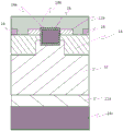
Fig. 7 is a diagram schematically showing a preferred example of a Schottky Barrier Diode (SBD).
Fig. 8 is a diagram schematically showing a preferred example of a High Electron Mobility Transistor (HEMT).
Fig. 9 is a diagram schematically showing a preferred example of a Metal Oxide Semiconductor Field Effect Transistor (MOSFET).
Fig. 10 is a diagram schematically showing a preferred example of a Junction Field Effect Transistor (JFET).
Fig. 11 is a view schematically showing a preferred example of an Insulated Gate Bipolar Transistor (IGBT).
Fig. 12 is a diagram schematically showing a preferred example of a light emitting element (LED).
Fig. 13 is a diagram schematically showing a preferred example of a light emitting element (LED).
Fig. 14 is a diagram schematically showing a preferred example of the power supply system.
Fig. 15 is a diagram schematically showing a preferred example of the system apparatus.
Fig. 16 is a diagram schematically showing a preferred example of a power supply circuit of the power supply device.
Fig. 17 is a diagram schematically showing a preferred example of a Heterojunction Bipolar Transistor (HBT).
Fig. 18 is a diagram schematically showing a preferred example of a Metal Oxide Semiconductor Field Effect Transistor (MOSFET).
FIG. 19 is a graph showing the results of I-V measurement in examples.
FIG. 20 is a schematic configuration diagram of a film forming apparatus used in examples.
FIG. 21 is a schematic configuration diagram of a film forming apparatus used in examples.
Fig. 22 is a graph showing XRD measurement results in the examples. The horizontal axis represents diffraction angle (deg.) and the vertical axis represents diffraction intensity (arb.
Fig. 23 is a graph showing XRD measurement results in examples. The horizontal axis represents diffraction angle (deg.) and the vertical axis represents diffraction intensity (arb.
Detailed Description
Preferred embodiments of the present invention will be described below.
The p-type oxide semiconductor film of the present invention is a p-type oxide semiconductor film having a diamond structure, in which the surface roughness (Ra) thereof is 100nm or less. Preferably, in the present invention, the surface roughness is 50nm or less. More preferably 10nm or less. The surface roughness (Ra) is a result of measuring the surface shape for a 10 μm square area measured by an Atomic Force Microscope (AFM), and is calculated according to JIS B0601.
The "metal oxide having a diamond structure" refers to a metal oxide including a crystalline layer having a diamond structure, and may include a layer (e.g., an amorphous layer) other than the crystalline layer having a diamond structure. Further, the crystalline layer of the diamond structure is preferably a single crystalline layer, but may be a polycrystalline layer.
The film thickness of the p-type oxide semiconductor film is not particularly limited, but is preferably 50nm or more, more preferably 100nm or more, and most preferably 1.0 μm or more. According to the present invention, a p-type oxide semiconductor film having excellent surface smoothness can be obtained even with a large film thickness.
The p-type oxide semiconductor film usually contains a metal oxide having a diamond structure as a main component. Preferably, the metal oxide contains a d-block metal of the periodic table or a group 13 metal of the periodic table. More preferably, the metal of group 9 or group 13 of the periodic table. Preferably, it contains iridium. The "main component" is preferably 50% or more, more preferably 70% or more, further preferably 90% or more, by atomic ratio, of the metal oxide, and may be 100% or more, with respect to all components of the p-type oxide semiconductor film. In the present invention, it is preferable that the p-type oxide semiconductor film contains a crystal or a mixed crystal of a metal oxide containing iridium. The "iridium-containing metal oxide" means an oxide containing iridium and oxygen, but Ir is preferable in the present invention2O3More preferably α -Ir2O3. In addition, when the metal oxide is a mixed crystal,preferably, the alloy contains iridium, a group 2 metal of the periodic table, and a mixed crystal of a group 9 metal or a group 13 metal other than iridium. According to the above preferred embodiment, since a product having an energy gap of 2.4eV or more can be obtained, a wider energy gap and more excellent electrical characteristics can be exhibited in the p-type oxide semiconductor film. In the present invention, it is preferable that the energy gap of the p-type oxide semiconductor film is 2.0eV or more.
In addition, the "periodic table" represents the periodic table defined by the International Union of Pure and Applied Chemistry (IUPAC). "d-block" refers to an element having electrons filling the 3d, 4d, 5d, and 6d orbitals. Examples of the d-block metal include scandium (Sc), titanium (Ti), vanadium (V), chromium (Cr), manganese (Mn), iron (Fe), cobalt (Co), nickel (Ni), copper (Cu), zinc (Zn), yttrium (Y), zirconium (Zr), niobium (Nb), molybdenum (Mo), technetium (Tc), ruthenium (Ru), rhodium (Rh), palladium (Pd), silver (Ag), cadmium (Cd), lutetium (Lu), hafnium (Hf), tantalum (Ta), tungsten (W), rhenium (Re), osmium (Os), iridium (Ir), platinum (Pt), gold (Au), mercury (Hg), rhodium (Lr), tsumadu (Rf), tsumadu (Db), tsumadu (Sg), tsumadai (Bh), tsumadai (Hs), mitsui (Mt), (Ds), chia (Cn), and 2 or more metals thereof.
The "group 2 metal" may Be a group 2 metal of the periodic table, and examples of the group 2 metal include beryllium (Be), magnesium (Mg), calcium (Ca), strontium (Sr), barium (Ba), 2 or more kinds of these metals, and the like. The "group 9 metal" may be a group 9 metal of the periodic table, and examples of such a group 9 metal include iridium (Ir), cobalt (Co), rhodium (Rh), and 2 or more kinds of metals thereof. The "group 13 metal" is not particularly limited as long as it is a group 13 metal of the periodic table, and examples of the group 13 metal include, for example, aluminum (Al), gallium (Ga), indium (In), thallium (Tl), and 2 or more kinds of metals thereof, but In the present invention, 1 kind or 2 or more kinds selected from aluminum (Al), gallium (Ga), and indium (In) are preferable.
The p-type oxide semiconductor film of the present invention can be preferably obtained by a method for forming such a p-type oxide semiconductor film, which is also novel and useful, and is included in one embodiment of the present invention.
The method for forming a p-type oxide semiconductor film according to the present invention is characterized in that a metal oxide gas is used as a raw material to perform crystal growth on a substrate having a diamond (corundum) structure in the formation of the p-type oxide semiconductor film. More specifically, for example, a solid (e.g., powder) of a metal oxide gas is sublimated (sublimation step), and then the resulting metal oxide gas is used to grow a crystal on a substrate having a diamond structure (crystal growth step).
(sublimation step)
The sublimation step is a step of sublimating a solid (for example, powder or the like) of the metal oxide gas into a gaseous state to obtain the metal oxide gas. The metal oxide gas is not particularly limited as long as the valence number of the metal oxide gas is not detrimental to the object of the present invention, and may be 1 or 2. And may have a valence of 3 or 4. In the present invention, in the case where the p-type oxide semiconductor film has a metal oxide containing iridium as a main component, IrO is preferably used2Gas is used as the metal oxide gas. The sublimation means may be heating means. The heating temperature is not particularly limited, but is preferably 600 to 1200 ℃, more preferably 800 to 1000 ℃. In the present invention, the metal oxide gas obtained by sublimation is preferably carried to the substrate with a carrier gas. The type of carrier gas is not particularly limited as long as it does not inhibit the object of the present invention, and examples thereof include an inert gas such as oxygen, ozone, nitrogen, or argon, or a reducing gas such as hydrogen gas or synthesis gas (forming gas). Examples of the carrier gas using oxygen include air, oxygen, ozone, and the like, and oxygen and/or ozone are particularly preferable. The kind of the carrier gas may be 1 kind or 2 or more kinds, and a diluent gas (for example, a 10-fold diluent gas) or the like in which the concentration of the carrier gas is changed may be used as the 2 nd carrier gas. The supply position of the carrier gas may be not only 1 position but also 2 or more positions. The flow rate of the carrier gas is not particularly limited, but is preferably 0.01 to 20L/min, more preferably 0.1 to 10L/min。
The material of the substrate is not particularly limited as long as it has a diamond structure and can support the p-type oxide semiconductor film, and the substrate may be a known substrate, an organic compound, or an inorganic compound.
The substrate is a plate-shaped substrate, and is not particularly limited as long as it is a support for the p-type oxide semiconductor film, and may be an insulator substrate, a semiconductor substrate, or a conductive substrate, but the substrate is preferably an insulator substrate, and is preferably a substrate having a metal film on a surface thereof.
(Crystal growth step)
In the crystal growth step, the metal oxide gas is crystal-grown in the vicinity of the surface of the substrate, and a film is formed on a part or the entire surface of the substrate. The crystal growth temperature is preferably lower than the heating temperature in the sublimation step, more preferably 900 ℃ or lower, and most preferably 500 to 900 ℃. Further, the crystal growth may be performed under any of a vacuum atmosphere, a non-oxygen atmosphere, a reducing gas atmosphere, and an oxidizing atmosphere, and may be performed under any of atmospheric pressure, pressurized pressure, and reduced pressure, as long as the object of the present invention is not impaired, but the present invention is preferably performed under an oxidizing atmosphere, more preferably atmospheric pressure, and even more preferably, under an oxidizing atmosphere and atmospheric pressure. The "oxidation environment" is not particularly limited as long as it is an environment in which crystals or mixed crystals of the metal oxide can be formed, and may be an environment in which a carrier gas containing oxygen or an oxidizing agent is used as the oxidation environment in the presence of oxygen or an oxygen-containing compound. The film thickness can be set by adjusting the film formation time. In the present invention, the particle size is preferably 50nm or more, more preferably 100nm or more, and most preferably 1.0 μm or more. The upper limit of the film thickness is not particularly limited, but is preferably 1mm, more preferably 100 μm. In the present invention, the metal oxide having a diamond structure may be p-doped by adding a p-type dopant to the metal oxide gas in this step. Examples of the P-type dopant include Mg, H, Li, Na, K, Rb, Cs, Fr, Be, Ca, Sr, Ba, Ra, Mn, Fe, Co, Ni, Pd, Cu, Ag, Au, Zn, Cd, Hg, Tl, Pb, N, P, and 2 or more kinds of these elements. In the present invention, the p-type dopant is preferably a group 1 metal or a group 2 metal of the periodic table, more preferably a group 2 metal, and most preferably magnesium (Mg). In the present invention, the p-type oxide semiconductor film obtained in this step may be subjected to annealing treatment.
In the present invention, the metal oxide gas may be obtained by, for example, evaporating a liquid (e.g., mist) of a precursor of the metal oxide gas and oxidizing the vapor as desired. In this case, the liquid material (for example, mist) of the precursor of the metal oxide gas is preferably mist obtained by atomizing or dropforming the raw material solution.
Hereinafter, as another preferable embodiment of the method for forming a p-type oxide semiconductor film of the present invention, a method for forming a p-type oxide semiconductor film in the case of using a metal oxide obtained by evaporating a liquid material (for example, mist or the like) of a precursor of a metal oxide gas and oxidizing the vapor in accordance with expectation will be described in more detail.
In the method for forming a p-type oxide semiconductor film according to the present invention, for example, a raw material solution containing a precursor of the metal oxide gas is atomized or dripped (atomization/dripping step) to obtain an atomized or dripped mist or droplets, which is evaporated or oxidized as desired (evaporation step) using a two-zone film forming apparatus shown in fig. 21, and then the obtained metal oxide gas is used to grow a crystal on a substrate having a diamond structure (crystal growth step). Here, the substrate and the crystal growth step may be the same as those in the method for forming a p-type oxide semiconductor film using the solid of the metal oxide gas. By forming the p-type oxide semiconductor film in this manner, the p-type oxide semiconductor film can be formed more favorably, and a p-type oxide semiconductor film excellent in semiconductor characteristics and surface smoothness can be obtained, unlike the case where a conventional aerosol CVD method or the like is used.
(atomization/dropletization step)
In the atomization/dropletization step, the raw material solution is atomized or dropletized. The atomizing means or the droplet-forming means of the raw material solution is not particularly limited as long as the raw material solution can be atomized or formed into droplets, and may be any known means. The mist or liquid droplets obtained by using the ultrasonic waves are preferably a mist having an initial velocity of zero and floating in the air, and for example, a mist which is not attached by spraying and is transported as a gas floating in the space, and therefore, is not damaged by collision energy, and is very suitable. The droplet size is not particularly limited, and may be about several millimeters, but is preferably 50 μm or less, more preferably 100nm to 10 μm.
(raw Material solution)
The raw material solution is a precursor containing the metal oxide gas, and is not particularly limited as long as it can be atomized or formed into droplets, and may contain an inorganic material or an organic material. In the present invention, the raw material solution preferably contains a metal or a compound thereof contained in the p-type oxide semiconductor film. In the present invention, it is preferable that the metal contained in the p-type oxide semiconductor film is dissolved or dispersed in an organic solvent or water in the form of a complex or a salt as the raw material solution. Examples of the form of the complex include acetylacetone complex, carbonyl complex, ammonia complex, and hydride complex. Examples of the salt form include organic metal salts (e.g., metal acetate, metal oxalate, and metal citric acid), metal sulfide salts, metal nitrifying salts, metal phosphoxide salts, and metal halide salts (e.g., metal chloride salts, metal bromide salts, and metal iodide salts).
In addition, it is preferable to mix an additive such as a halogen acid or an oxidizing agent into the raw material solution. Examples of the hydrohalic acid include hydrobromic acid, hydrochloric acid, hydroiodic acid, and the like, and among them, hydrobromic acid or hydroiodic acid is preferable because a film having a higher quality can be obtained. Examples of the oxidizing agent include hydrogen peroxide (H)2O2) Sodium peroxide (Na)2O2) Barium peroxide (BaO)2) Benzoyl peroxide (C)6H5CO)2O2And organic oxides such as hypochlorous acid (HClO), perchloric acid, nitric acid, ozone water, peracetic acid, and nitrobenzene.
The dopant is not particularly limited as long as it does not inhibit the object of the present invention, and examples of the dopant include P-type dopants such as Mg, H, Li, Na, K, Rb, Cs, Fr, Be, Ca, Sr, Ba, Ra, Mn, Fe, Co, Ni, Pd, Cu, Ag, Au, Zn, Cd, Hg, Tl, Pb, N, P, etc., and the concentration of the dopant is usually about 1 × 10¹⁶/cm3~1×1022/cm3And, the concentration of the dopant may be set to, for example, about 1 × 10¹⁷/cm3The following low concentration, and, in the present invention, about 1 × 10 may be further used20/cm3The above high concentrations contain dopants.
The solvent of the raw material solution is not particularly limited, and may be an inorganic solvent such as water, an organic solvent such as alcohol, or a mixed solvent of an inorganic solvent and an organic solvent. In the present invention, it is preferable that the solvent contains water, and more preferable is water or a mixed solvent of water and alcohol.
(Evaporation step)
In the evaporation step, the metal oxide gas may be obtained by evaporating a liquid substance (e.g., mist or the like) of a precursor of the metal oxide gas and oxidizing it as desired. The metal oxide gas may be the same as that in the sublimation step described above. Further, examples of the evaporation means include a heating means. The heating temperature in the evaporation means may be the same as the heating temperature in the sublimation means. In the present invention, the metal oxide gas obtained by evaporation is preferably carried to the substrate by a carrier gas. The type of the carrier gas is not particularly limited as long as it does not inhibit the object of the present invention, and examples thereof include an inert gas such as oxygen, ozone, nitrogen or argon, or a reducing gas such as hydrogen or a synthesis gas, and oxygen and/or ozone is particularly preferable. In the present invention, the precursor of the metal oxide gas can be preferably oxidized by using oxygen and/or ozone as the carrier gas. The carrier gas may be 1 kind or 2 kinds, and a diluent gas (for example, a 10-fold diluent gas) or the like in which the concentration of the carrier gas is changed may be used as the 2 nd carrier gas. The supply position of the carrier gas may be not only 1 position but also 2 or more positions. The flow rate of the carrier gas is not particularly limited, but is preferably 0.01L/min to 20L/min, more preferably 0.1L/min to 10L/min.
As described above, the obtained p-type oxide semiconductor film can be preferably used as a p-type semiconductor layer by a known method. In the present invention, the p-type oxide semiconductor film can be formed using a gas obtained by sublimating a solid (for example, powder or the like) of the metal oxide gas as the metal oxide gas, and the p-type oxide semiconductor film can be formed more favorably, and for example, a p-type oxide semiconductor film excellent in surface smoothness of surface roughness of 5nm or less can be obtained, which is preferable. In the present invention, a film can be formed directly on the substrate, or a semiconductor layer different from the p-type semiconductor layer can be stacked on the substrate (for example,n-type semiconductor layer, n + type semiconductor layer, n-type semiconductor layer, etc.) or an insulator layer (including a semi-insulator layer), a buffer layer, etc. and then film-formed on the substrate with another layer interposed therebetween, examples of the semiconductor layer or the insulator layer include, for example, a semiconductor layer or an insulator layer including the group 13 metal, and examples of the buffer layer include, for example, a semiconductor layer including a diamond structure, an insulator layer, a conductor layer, etc. preferred examples include, for example, a semiconductor layer including a diamond structure, α -Fe, etc. as the semiconductor layer including a diamond structure2O3、α-Ga2O3、α-Al2O3And the like. The buffer layer may be formed by the same method as the method for forming the p-type oxide semiconductor, without any particular limitation.
In the present invention, it is preferable that the n-type semiconductor layer is formed before or after the p-type semiconductor layer is formed. More specifically, the method of manufacturing a semiconductor device preferably includes a step of stacking at least a p-type semiconductor layer and an n-type semiconductor layer. The means for forming the n-type semiconductor layer is not particularly limited, and may be a known means, and in the present invention, an atomized CVD method is preferable. The n-type semiconductor layer is preferably composed mainly of an oxide semiconductor, and more preferably composed mainly of an oxide semiconductor containing a group 13 metal of the periodic table (e.g., Al, Ga, In, Tl, etc.). The n-type semiconductor layer preferably contains a crystalline oxide semiconductor as a main component, more preferably contains a crystalline oxide semiconductor containing Ga as a main component, and most preferably contains a crystalline oxide semiconductor having a diamond structure and containing Ga as a main component. In the present invention, it is preferable that the difference in lattice constant between the oxide semiconductor which is the main component of the n-type semiconductor and the p-type oxide semiconductor is 1.0% or less because a good pn junction can be formed, and more preferably 0.3% or less. Here, "lattice constant difference" is defined as follows: the lattice constant of the p-type oxide semiconductor is subtracted from the lattice constant of the oxide semiconductor that is the main component of the n-type semiconductor, the value is divided by the lattice constant of the p-type oxide semiconductor, and the absolute value of the value is multiplied by a value (%) that is 100 times. Examples of the case where the difference in lattice constant is 1.0% or less includeThe case where the p-type oxide semiconductor has a diamond structure, and the case where the oxide semiconductor which is the main component of the n-type semiconductor also has a diamond structure, and the like, a more preferable example is a case where the p-type oxide semiconductor is Ir2O3Is Ga as a single crystal or mixed crystal, and the oxide semiconductor which is a main component of the n-type semiconductor2O3The case of single crystals or mixed crystals, etc. The "main component" is an oxide semiconductor which is contained in an atomic ratio of preferably 50% or more, more preferably 70% or more, further preferably 90% or more, and may be 100% to the entire components of the n-type semiconductor layer. In the present invention, the p-type oxide semiconductor may be single crystal, polycrystalline, or the like.
The p-type oxide semiconductor film obtained by the above preferred formation method is industrially applicable and has excellent electrical characteristics. More specifically, the mobility is usually at 1.0cm2More than V.s. The mobility is measured by Hall effect, and is preferably 3.0cm in the present invention2More than Vs, and in the p-type oxide semiconductor film, the carrier density is preferably 8.0 × 10²⁰/cm3Here, the carrier density refers to the carrier density in the semiconductor film obtained by Hall effect measurement, and the lower limit of the carrier density is not particularly limited, but is preferably about 1.0 × 10¹⁵/cm3Above, more preferably about 1.0 × 10¹⁷/cm3In the present invention, the carrier density can be easily controlled to 1.0 × 10 by adjusting the type and amount of the dopant or the material of the mixed crystal and the content thereof16/cm3~1.0×1020/cm3Within the range of (1).
The p-type oxide semiconductor film obtained as described above can be used as a p-type semiconductor layer in a semiconductor device, and is particularly useful in a power device. When the p-type oxide semiconductor film is used for a semiconductor device, roughness scattering can be suppressed, and the channel mobility of the semiconductor device can be improved. Further, the semiconductor device can be classified into a horizontal device (horizontal device) in which an electrode is formed on one surface side of a semiconductor layer and a vertical device (vertical device) in which electrodes are formed on both the front surface and the back surface of the semiconductor layer. Examples of the semiconductor device include a Schottky Barrier Diode (SBD), a metal semiconductor field effect transistor (MESFET), a High Electron Mobility Transistor (HEMT), a Metal Oxide Semiconductor Field Effect Transistor (MOSFET), a Static Induction Transistor (SIT), a Junction Field Effect Transistor (JFET), an Insulated Gate Bipolar Transistor (IGBT), a light emitting diode, and the like.
Fig. 7 to 13 show an example in which a p-type oxide semiconductor film is used for the p-type semiconductor layer. The n-type semiconductor may be an n-type semiconductor having the same main component as the p-type oxide semiconductor and containing an n-type dopant, or may be an n-type semiconductor having a different main component from the p-type oxide semiconductor. In addition, an n-type semiconductor is suitably used as the n-type semiconductor layer, the n + -type semiconductor layer, or the like by using a known means such as adjusting the content of an n-type dopant.
Fig. 7 shows a preferred example of a Schottky Barrier Diode (SBD), which includes an n-type semiconductor layer 101a, an n + -type semiconductor layer 101b, a p-type semiconductor layer 102, a metal layer 103, an insulator layer 104, a schottky electrode 105a, and an ohmic electrode 105 b. The metal layer 103 is made of, for example, a metal such as Al, and covers the schottky electrode 105 a. Fig. 8 shows a preferred example of a High Electron Mobility Transistor (HEMT) including a wide band gap n-type semiconductor layer 121a, a narrow band gap n-type semiconductor layer 121b, an n + -type semiconductor layer 121c, a p-type semiconductor layer 123, a gate electrode 125a, a source electrode 125b, a drain electrode 125c, and a substrate 129.
The material of the schottky electrode and the ohmic electrode may be a known electrode material. Examples of the electrode material include metals such as Al, Mo, Co, Zr, Sn, Nb, Fe, Cr, Ta, Ti, Au, Pt, V, Mn, Ni, Cu, Hf, W, Ir, Zn, In, Pd, Nd, or Ag, and alloys thereof; a metal oxide conductive film such as tin oxide, zinc oxide, Indium Tin Oxide (ITO), Indium Zinc Oxide (IZO), or the like; and organic conductive compounds such as polyaniline, polythiophene, or polypyrrole, or mixtures thereof.
The schottky electrode and the ohmic electrode can be formed by a known method such as vacuum evaporation or sputtering. More specifically, for example, in the case of forming a schottky electrode, a layer made of Mo and a layer made of Al may be stacked, and patterned using a photolithography technique.
Examples of the material of the insulating layer include GaO, AlGaO, InAlGaO, and AlInZnGaO4、AlN、Hf2O3、SiN、SiON、Al2O3、MgO、GdO、SiO2Or Si3N4. In the present invention, it is preferable to have a diamond structure. The insulator layer can be formed by a known method such as a sputtering method, a vacuum deposition method, or a CVD method.
Fig. 9 shows a preferred example of a Metal Oxide Semiconductor Field Effect Transistor (MOSFET) including an n-type semiconductor layer 131a, a first n + -type semiconductor layer 131b, a second n + -type semiconductor layer 131c, a p-type semiconductor layer 132, a p + -type semiconductor layer 132a, a gate insulating film 134, a gate electrode 135a, a source electrode 135b, and a drain electrode 135 c. In addition, the p + -type semiconductor layer 132a may be a p-type semiconductor layer, or may be the same as the p-type semiconductor layer 132. Fig. 10 shows a preferred example of a Junction Field Effect Transistor (JFET), which includes an n-type semiconductor layer 141a, a first n + -type semiconductor layer 141b, a second n + -type semiconductor layer 141c, a p-type semiconductor layer 142, a gate electrode 145a, a source electrode 145b, and a drain electrode 145 c. Fig. 11 shows a preferred example of a gate type bipolar transistor (IGBT) including an n-type semiconductor layer 151, an n-type semiconductor layer 151a, an n + -type semiconductor layer 151b, a p-type semiconductor layer 152, a gate insulating film 154, a gate electrode 155a, an emitter electrode 155b, and a collector electrode 155 c.
(LED)
Fig. 12 shows an example of the case where the semiconductor device of the present invention is a Light Emitting Diode (LED). The semiconductor light emitting element of fig. 12 includes an n-type semiconductor layer 161 on the second electrode 165b, and a light emitting layer 163 is stacked on the n-type semiconductor layer 161. On the light-emitting layer 163, a p-type semiconductor layer 162 is stacked. A light-transmitting electrode 167 through which light generated in the light-emitting layer 163 is transmitted is provided on the p-type semiconductor layer 162, and a first electrode 165a is stacked on the light-transmitting electrode 167. The luminophores used for the luminescent layer may be known devices. Also, the semiconductor light emitting element of fig. 12 may be covered with a protective layer except for the electrode portion.
As a material of the light-transmissive electrode, a conductive material containing an oxide such as indium (In) or titanium (Ti) can be given. More specifically, for example, In2O3、ZnO、SnO2、Ga2O3、TiO2、CeO2Or a mixed crystal of two or more of these, or the aforementioned material being doped. These materials can be used to form the light-transmissive electrode by a known method such as sputtering. After the light-transmissive electrode is formed, thermal annealing may be performed for the purpose of making the light-transmissive electrode transparent.
According to the semiconductor light emitting device of fig. 12, the first electrode 165a functions as a positive electrode, the second electrode 165b functions as a negative electrode, and current is passed through the p-type semiconductor layer 162, the light emitting layer 163, and the n-type semiconductor layer 161 with the foregoing two interposed therebetween, so that the light emitting layer 163 emits light.
Examples of the material of the first electrode 165a and the second electrode 165b include metals such as Al, Mo, Co, Zr, Sn, Nb, Fe, Cr, Ta, Ti, Au, Pt, V, Mn, Ni, Cu, Hf, W, Ir, Zn, In, Pd, Nd, or Ag, and alloys thereof; a metal oxide conductive film such as tin oxide, zinc oxide, Indium Tin Oxide (ITO), or zinc indium oxide (IZO); organic conductive compounds such as polyaniline, polythiophene, polypyrrole, or the like, or mixtures thereof. The method for forming the electrode is not particularly limited, and the following method may be appropriately selected in consideration of the suitability of the material to form the electrode on the substrate: wet methods such as printing, spraying, coating; physical methods such as vacuum evaporation, sputtering, and ion plating; and chemical methods such as CVD and plasma CVD.
Fig. 13 shows another embodiment of the light-emitting element. In the light emitting element of fig. 13, an n-type semiconductor layer 161 is stacked on a substrate 169, a semiconductor layer exposed surface is exposed by cutting out a portion of the p-type semiconductor layer 162, the light emitting layer 163 and the n-type semiconductor layer 161, and a second electrode 165b is stacked on a portion of the semiconductor layer exposed surface of the n-type semiconductor layer 161.
(HBT)
Fig. 17 shows an example of a case where the semiconductor device of the present invention is a Heterojunction Bipolar Transistor (HBT). The HBT of fig. 17 may have an npn structure or a pnp structure. Hereinafter, the npn structure will be described in detail, and the case of the pnp structure is the same. The p-type layer of npn structure can be replaced by an n-type layer of pnp structure and vice versa. The substrate 60 may be a semi-insulating substrate and may have a high resistivity (e.g., a resistivity in excess of 10)5Ω cm, etc.). In addition, the substrate 60 may be n-type.
In the present embodiment, particularly when the substrate 60 is semi-insulating, the sub-collector layer 40 may be formed between the collector layer 42 and the substrate 60. Preferably, sub-collector layer 40 includes an n + -type oxide semiconductor having a diamond structure as a main component. Preferably, the n + -type oxide semiconductor is mainly composed of an oxide semiconductor including a metal of group 13 of the periodic table (e.g., Al, Ga, In, Tl, etc.). More preferably, an oxide semiconductor containing one or two or more metals selected from aluminum, indium, and gallium is used as a main component. Gallium oxide or mixed crystals thereof are most preferred. Here, the "main component" is the same as the aforementioned "main component". The thickness of the subcollector layer 40 is preferably about 0.1 to 100 μm. On the surface of the sub-collector layer 40, a collector 52 is formed. The purpose of subcollector layer 40 is to improve the performance of ohmic collector 52. Also, if the substrate 60 has conductivity, the sub-collector layer 40 may be omitted.
The base layer 44 is formed on the collector layer 42. The base layer 44 is not particularly limited as long as it contains the p-type oxide semiconductor of the present invention as a main component. Although the thickness of the base layer 44 is not particularly limited, it is preferably 10nm to 10 μm, more preferably 10nm to 1 μm. More preferably, the base layer 44 is formed by gradually changing the composition of any base layer 44 from the contact portion with the collector layer 42 to the vicinity of the top surface of the base layer 44. In another embodiment, a superlattice may be stacked on the top surface of the base layer 44.
An emitter layer 46 is formed on the base layer 44. The emitter layer 46 preferably contains an n-type oxide semiconductor having a diamond structure as a main component. Preferably, the n-type oxide semiconductor is mainly composed of an oxide semiconductor including a metal of group 13 of the periodic table (e.g., Al, Ga, In, Tl, etc.). More preferably, an oxide semiconductor containing one or two or more metals selected from aluminum, indium, and gallium is used as a main component. Gallium oxide or mixed crystals thereof are most preferred. Here, the "main component" is the same as the aforementioned "main component". Also, the thickness of the emitter layer 46 is not particularly limited, but is preferably 10nm to 100 μm. The emitter layer 46 typically has a wider bandgap than the base layer 44. More preferably, the emitter layer 46 gradually changes the composition of any one emitter layer 46 from the portion in contact with the base layer 44 to near the top surface of the emitter layer 46.
Preferably, a cap layer 48 is formed on the emitter layer 46. The cap layer 48 is preferably an n + type oxide semiconductor having a diamond structure. An n + -type oxide semiconductor including one or two or more metals selected from aluminum, indium, and gallium is preferable. Most preferably n + doped gallium oxide or a mixed crystal thereof. The thickness thereof is not particularly limited, but is preferably 10nm to 100 μm. Etching, for example, is performed on these layers to expose the base layer 44, while providing an upwardly oriented collector, a deeper via may be formed, for example, by etching, to expose the subcollector layer 40.
Each of the collector electrode 52, base electrode 54 and emitter electrode 56 is preferably an ohmic metal electrode. An emitter electrode 56 is stacked on the cap layer 48, and a base electrode 54 is stacked on the base layer 44 exposed by, for example, etching or the like. Collector electrode 52 is stacked on subcollector layer 40 as described above. In another embodiment, when the substrate 60 is an n-type semiconductor or the like, a collector (not shown) is usually provided on the back surface of the substrate 60 on the side opposite to the device structure.
The material of each electrode is not particularly limited, and known electrode materials may be used, respectively. Preferred compositions for the electrode include known ohmic electrode materials (e.g., Ni, Al, Ti, Pt, Au, and a laminate thereof). The thickness of each electrode m is not particularly limited, but is preferably about 10 to about 100 μm, and the deposition of each electrode can be achieved by electron beam evaporation, thermal evaporation, sputtering, or other techniques. Also, after each electrode material is stacked, an annealing process may be performed to achieve ohmic contact. The annealing temperature is not particularly limited, but is preferably about 300 to 1000 ℃.
In addition, a pnp HBT can be formed by replacing the p-type layer of a pnp HBT with an n-type layer of an npn HBT, and vice versa.
In the present invention, a p-type oxide semiconductor film is preferably used for the semiconductor devices in the following (1) to (3).
(1) Semiconductor device including p-type channel layer
A semiconductor device (1) comprises at least a gate electrode and a channel layer, the channel layer forming a channel on the sidewall of the gate electrode directly or via other layers, wherein a part or the whole of the channel layer contains a p-type oxide semiconductor as a main component. The channel layer is not particularly limited as long as a channel is formed, and the channel layer may be a part of a semiconductor layer or the entire part thereof, or may be formed so as to straddle another semiconductor layer. By using a p-type oxide semiconductor film for a p-type semiconductor layer, it is possible to use a semiconductor device in which semiconductor characteristics of an n-type semiconductor (for example, gallium oxide or the like) which is low in loss at a high voltage at which the dielectric breakdown field strength is much higher than that of SiC are not deteriorated without implanting ions or the like.
In addition, the semiconductor device (1) is preferably further built with an SBD. By building the SBD, the on-voltage can be reduced and the follow current can flow more easily, so that excellent semiconductor characteristics favorable for industry can be obtained.
(2) Semiconductor device including p-well layer
The semiconductor device (2) is a semiconductor device including at least an n-type semiconductor layer and a p + -type semiconductor layer, wherein the n-type semiconductor layer contains a crystalline oxide semiconductor containing a metal of group 13 of the periodic table as a main component, and the p + -type semiconductor layer contains a p-type oxide semiconductor film as a main component. A p-type oxide semiconductor film can be used for the p-well layer.
(3) Semiconductor device including electric field shielding layer
The semiconductor device (3) is a semiconductor device comprising at least an n-type semiconductor layer containing a crystalline oxide semiconductor having a diamond structure as a main component, an electric field shielding layer stacked on the n-type semiconductor layer directly or via other layers, respectively, wherein the electric field shielding layer comprises a p-type oxide semiconductor and is buried deeper in the n-type semiconductor layer than the gate electrode. By providing the electric field shielding layer in this manner, a leakage current in the reverse direction can be reduced.
FIG. 18 shows a preferred semiconductor device including the above-mentioned (1) to (3). The semiconductor device shown in fig. 18 includes a first n + -type semiconductor layer 11a, an n-type semiconductor layer 12, a p-type semiconductor layer 13, a second n + -type semiconductor layer 11b, a p + -type semiconductor layer 16, a gate electrode 14a, a gate insulating film 15, a schottky electrode 14b, and a drain electrode 14 c. In the ON (ON) state of the semiconductor device of fig. 18, when a voltage is applied between the source electrode 14b and the drain electrode 14c and a positive charge is given to the gate electrode 14a with respect to the source electrode 14b, a channel is formed at the interface of the p-type semiconductor layer 13 and the gate insulating film 15 and is conducted. In the OFF (OFF) state, the gate electrode 14a is set to 0V, and is turned OFF without forming a channel. In the semiconductor device of fig. 18, the p-type semiconductor layer 13 is buried deeper in the n-type semiconductor layer 12 than the gate electrode 14 a. By adopting such a configuration, it is possible to reduce a leakage current in the reverse direction and improve the breakdown voltage.
The means for forming each layer of the semiconductor device in fig. 18 is not particularly limited as long as the object of the present invention is not impaired, and may be a known means. Examples thereof include a method of forming a film by a vacuum deposition method, a CVD method, a sputtering method, various coating techniques, and the like, and then patterning the film by a photolithography method, and a method of directly patterning the film by a printing technique and the like. In the semiconductor device of fig. 18, the second n + -type semiconductor layer 11b and the p + -type semiconductor layer 16 are continuously provided with the source electrode 14b interposed therebetween, but the second n + -type semiconductor layer 11b and the p + -type semiconductor layer 16 may be directly continuously provided without interposing the source electrode 14b therebetween. Although not shown, in the case where the second n + -type semiconductor layer 11b and the p + -type semiconductor layer 16 are directly provided in series, when the p + -type semiconductor layer 16 is wider than the second n + -type semiconductor layer 11b, an effect of making the hole escape good is obtained. In addition, when the second n + type semiconductor layer 11b is wider than the p + type semiconductor layer 16, an effect of reducing the on-resistance is achieved.
Semiconductor devices are particularly useful for power devices. Examples of the semiconductor device include a diode (e.g., SBD) and a transistor (e.g., MESFET or JFET). More preferably an SBD, MOSFET, IGBT or JFET, most preferably a MOSFET or JFET. Further, it is preferable that the semiconductor device includes an SOI structure including a silicon substrate and a buried insulating layer formed on the silicon substrate, so that an operation at higher temperature can be realized.
In addition to the above, the semiconductor device of the present invention can be preferably used as a power module (power module), an inverter, or a converter (converter) by a known means, and is more preferably used in, for example, a semiconductor system using a power supply device. The power supply device can be manufactured by connecting the semiconductor device to a wiring pattern or the like by a known means. Fig. 14 shows an example of a power supply system. Fig. 14 uses a plurality of power supply devices and control circuits to constitute a power supply system. As shown in fig. 15, the power supply system can be combined with an electronic circuit to be used in a system device. Further, fig. 16 shows an example of a power supply circuit diagram of the power supply device. Fig. 16 shows a power supply circuit of a power supply device including a power circuit and a control circuit, in which a DC voltage is switched at a high frequency by an inverter (MOSFET: formed by a to D) to be converted to AC, then insulated and transformed by a transformer, rectified by rectifying MOSFETs (a to B'), smoothed by DCLs (smoothing coils L1 and L2) and a capacitor, and a DC voltage is output. At this time, the output voltage is compared with a reference voltage by a voltage comparator, and the inverter and the rectifying MOSFET are controlled by a PWM control circuit to form a desired output voltage.
[ examples ]
(example 1)
1. Film forming apparatus
The film formation apparatus used in this example will be described with reference to fig. 1. The film forming apparatus 1 of fig. 1 includes: a quartz cylinder 2 connected to a carrier gas supply source; and a quartz-made raw material setting table 4 disposed in the quartz cylinder 2; the raw material 5 is placed on the raw material installation table 4. The raw material 5 is heated by a heater 3 cylindrically provided outside the quartz cylinder 2 around the raw material installation table. Further, a quartz substrate stage is provided as a stage 7 inside the quartz cylinder 2, and the stage 7 can be adjusted in its installation position so as to be within a crystal growth temperature.
2. Preparation for film formation
IrO is placed on the raw material installation table 42The powder was used as a raw material 5, and a sapphire substrate was set on a stage 7 as a substrate 6. Then, the temperature of the heater 3 was raised to 850 ℃ to mount IrO on the material mounting table 42The powder is heated, thereby making IrO2The powder sublimes to produce gaseous iridium oxide.
3. Forming a film
Next, the temperature of the heater 3 was maintained at 850 ℃, and in this state, a carrier gas was supplied from a carrier gas supply source into the quartz cylinder 2, and the metal oxide gas (gaseous iridium oxide) generated in the above 2 was supplied to the substrate 6 through the quartz cylinder 2. The flow rate of the carrier gas was 1.0L/min, and oxygen was used as the carrier gas. The metal oxide gas reacts near the surface of the substrate 6 under atmospheric pressure, and a film is formed on the substrate. The film formation time was 60 minutes, and the film thickness was 220 nm. The substrate temperature during film formation was 600 ℃.
4. Evaluation of
As a result of identifying the film obtained in the above 3, the film obtained was α -Ir2O3In addition, the results of XRD are shown in FIG. 3, and are for the resulting α -Ir2O3Hall effect measurements were taken of the film, resulting in an F value of 0.998, a carrier type of "p", known as p-type semiconductor, and a carrier concentration of 1.05 × 10²²(/cm3) Mobility of 3.12 (cm)2/V·s)。
Further, as a result of observing the film surface with an Atomic Force Microscope (AFM), as shown in FIG. 4, it was found that the surface smoothness was very excellent since the surface roughness (Ra) was 3.5nm, and the surface roughness (Ra) was 90 × 90 μm using an Atomic Force Microscope (AFM)2The results of measuring the surface shape were calculated according to JIS B0601.
Comparative example 1
1. Film forming apparatus
The atomized CVD apparatus used in this comparative example will be described with reference to fig. 2. The atomizing CVD apparatus 19 includes: a stage 21 on which the substrate 20 is placed; a carrier gas supply means 22a for supplying a carrier gas; a flow rate adjusting valve 23a for adjusting the flow rate of the carrier gas sent from the carrier gas supply means 22 a; a carrier gas (dilution) supply means 22b for supplying a carrier gas (dilution); a flow rate adjusting valve 23b for adjusting the flow rate of the carrier gas sent from the carrier gas (dilution) supply means 22 b; a mist generation source 24 for storing a raw material solution 24 a; a container 25 filled with water 25 a; an ultrasonic vibration element 26 attached to the bottom surface of the container 25; a supply pipe 27 made of a quartz tube having an inner diameter of 40 mm; and a heater 28 disposed around the supply pipe 27. The stage 21 is made of quartz, and a surface on which the substrate 20 is placed is inclined with respect to a horizontal plane. The supply pipe 27 as a film forming chamber and the stage 21 are both made of quartz, thereby suppressing impurities from the apparatus from mixing into the film formed on the substrate 20.
2. Preparation of raw Material solution
Iridium chloride (iridium concentration 0.1mol/L) and gallium bromide (gallium concentration 0.1mol/L) were mixed in ultrapure water, and hydrochloric acid was added so that the volume ratio became 20% to adjust the aqueous solution, which was used as a raw material solution. In addition, the volume ratio of iridium chloride to gallium bromide was 19: 1.
3. preparation for film formation
The raw material solution 24a obtained in the above 2 is stored in the mist generation source 24. Next, the c-plane sapphire substrate was set on the stage 21 as the substrate 20, and the temperature of the heater 28 was raised to 750 ℃. Next, the flow rate adjusting valves 23a and 23b were opened, carrier gas was supplied into the supply pipe 27 from the carrier gas supply means 22a and 22b as a carrier gas source, the atmosphere in the supply pipe 27 was sufficiently replaced with carrier gas, and then the flow rate of carrier gas was adjusted to 1.0L/min and the flow rate of carrier gas (diluted) was adjusted to 0.5L/min. In addition, oxygen is used as a carrier gas.
4. Forming a film
Subsequently, the ultrasonic vibration element is vibrated, and the vibration is transmitted to the raw material solution 24a through the water 25, whereby the raw material solution 24a is atomized to generate mist. The mist is carried to the supply pipe 27 by the carrier gas, and thermally reacted near the surface of the substrate 20 at 750 ℃ under atmospheric pressure to form a film on the substrate 20. The film thickness was 280 nm.
As a result of identifying the film obtained in the above 4, the film obtained was α -Ir2O3In addition, the results of XRD are shown in FIG. 3, and are for the resulting α -Ir2O3The film was Hall effect measured and found to have an F value of 0.998, a carrier type of "p", known as p-type semiconductor, and a carrier concentration of 2.97 × 10²¹(/cm3) Mobility of 0.38 (cm)2V · s) and the surface roughness (Ra) was 302nm as shown in fig. 5, and the surface roughness (Ra) was 90 × 90 μm for an amount of 90 by Atomic Force Microscope (AFM)2The result of measuring the surface shape in accordance with JIS B0601And (6) discharging.
(example 2 and comparative example 2)
Films were obtained in the same manner as in example 1 and comparative example 1 except that the film formation time was increased, and they were used as example 2 and comparative example 2, respectively. Next, the obtained film was observed for cross section by SEM. The results are shown in FIG. 6. As is clear from fig. 6, the film obtained in example 2 is a film, whereas the film obtained in comparative example 2 grows into a needle shape and does not have a homogeneous film shape.
From the results of examples and comparative examples, it is understood that the p-type oxide semiconductor film of the present invention is industrially useful because of excellent film quality such as surface smoothness and crystallinity, and also has excellent electrical characteristics such as mobility.
(example 3)
An n-type semiconductor layer was stacked over the p-type oxide semiconductor film in the same manner as in example 1, except that the film formation time was set to 2 hours, and that an n-type semiconductor layer was stacked over the p-type oxide semiconductor film, in which gallium bromide (gallium concentration: 0.1mol/L) and ultrapure water were mixed, hydrobromic acid was added to the mixture so that the volume ratio of the mixture became 20%, an aqueous solution was adjusted to obtain a raw material solution, the temperature of the heater was set to 420 ℃ and the film formation time was set to 30 minutes, and a film was formed in the same manner as in comparative example 1, wherein α -Ga was used as the film2O3And (3) a membrane.
Then, an n + -type semiconductor layer is stacked on the obtained n-type semiconductor layer. The stacking of the n + -type semiconductor layers is performed in the following manner: a film was formed in the same manner as in comparative example 1 except that gallium bromide (gallium concentration: 0.1mol/L) and ultrapure water were mixed, hydrobromic acid was added so that the volume ratio became 10% to adjust the aqueous solution, and germanium oxide 1% was further added as a raw material solution, the temperature of the heater was set to 390 ℃.
On the n + type semiconductor layer of the obtained laminate, Ti was formed by sputtering, and then photolithography and etching were performed to fabricate a pn diode. For the resulting pn-diode, an I-V measurement is performed. The results are shown in FIG. 19. As is clear from fig. 19, the p-type oxide semiconductor film of the present invention can realize, for example, an n-type semiconductor (for example, gallium oxide or the like) with low loss at a high voltage with a high dielectric breakdown field strength, and can realize a good PN junction.
(example 4)
1. Film forming apparatus
The film deposition apparatus used in this example will be described with reference to fig. 20. The film forming apparatus 10 of fig. 20 includes: a quartz cylinder 2 connected to a carrier gas supply source; a quartz material setting table 4 disposed in the quartz cylinder 2; the raw material 5 is placed on the raw material installation table 4. A heater (raw material side) 3a and a heater (substrate side) 3b are respectively provided in a cylindrical shape outside the quartz cylinder 2 around the raw material installation table, and the raw material 5 is heated. Further, a quartz substrate stage is provided as a stage 7 inside the quartz cylinder 2, and the stage 7 can be adjusted in the installation position so as to be within the crystal growth temperature.
2. Preparation for film formation
IrO is mounted on the mounting table 4 for raw material2The powder was used as a raw material 5, and a sapphire substrate was set on a stage 7 as a substrate 6. Then, the temperature of the heater (raw material side) 3a was raised to 850 ℃ to place IrO on the raw material mounting table 42The powder is heated, thereby making IrO2The powder sublimes to produce gaseous iridium oxide. In addition, the temperature of the heater (substrate side) 3b was raised to 350 ℃.
3. Forming a film
Next, the temperature of the heater (raw material side) 3a was maintained at 850 ℃, and the temperature of the heater (substrate side) was maintained at 350 ℃, in this state, a carrier gas was supplied from a carrier gas supply source into the quartz cylinder 2, and the metal oxide gas (gaseous iridium oxide) generated in the above 2 was supplied to the substrate 6 through the quartz cylinder 2. The flow rate of the carrier gas was 2.0L/min, and oxygen was used as the carrier gas. The metal oxide gas reacts near the surface of the substrate 6 under atmospheric pressure, thereby forming a film on the substrate. The film formation time was 90 minutes.
4. Evaluation of
As a result of identifying the film obtained in the above 3, the film obtained was α -Ir2O3The results of XRD are shown in FIG. 22, and it is found that the surface roughness (Ra) of the film surface was 0.161nm and the surface smoothness was very excellent by observing the film surface with an Atomic Force Microscope (AFM). the surface roughness (Ra) was 90 × 90 μm with an Atomic Force Microscope (AFM)2The results of measuring the surface shape were calculated according to JIS B0601.
(example 5)
A p-type oxide semiconductor film was obtained in the same manner as in example 4 except that the temperature of the heater (substrate side) was set to 250 ℃, the flow rate of the carrier gas was set to 4.0L/min, and the film formation time was set to 120 minutes, and the obtained film was identified by an X-ray diffraction apparatus, and as a result, the obtained film was α -Ir2O3The obtained film was very excellent in surface roughness (Ra) as in example 4, and was oriented to α -Ir2O3Hall Effect measurement was performed on the film, the F value was 0.999, the carrier type was "p", which is known as a p-type semiconductor, and the carrier concentration was 1.64 × 10²¹(/cm3) Mobility of 1.63 (cm)2/V·s)。
(example 6)
1. Film forming apparatus
The film deposition apparatus used in this embodiment will be described with reference to fig. 21. The film forming apparatus 30 of fig. 21 includes: a stage 21 on which the substrate 20 is placed; a carrier gas supply means 22a for supplying a carrier gas; a flow rate adjusting valve 23a for adjusting the flow rate of the carrier gas sent from the carrier gas supply means 22 a; a carrier gas (dilution) supply means 22b for supplying a carrier gas (dilution); a flow rate adjusting valve 23b for adjusting the flow rate of the carrier gas sent from the carrier gas (dilution) supply means 22 b; a mist generation source 24 for storing a raw material solution 24 a; a container 25 filled with water 25 a; an ultrasonic vibration element 26 attached to the bottom surface of the container 25; a supply pipe 27 made of a quartz tube having an inner diameter of 40 mm; and a heater (raw material side) 28a and a heater (substrate side) 28b provided around the supply pipe 27. The supply pipe 27 is composed of two regions: a supply pipe (raw material side) 27a provided with a heater (raw material side) 28a, and a supply pipe (substrate side) 27b provided with a heater (substrate side) 28 b. The stage 21 is made of quartz, and a surface on which the substrate 20 is placed is inclined with respect to a horizontal plane. The supply pipe 27 as a film forming chamber and the stage 21 are both made of quartz, thereby suppressing impurities from the apparatus from being mixed into the film formed on the substrate 20.
2. Preparation of raw Material solution
Iridium bromide (iridium concentration: 0.1mol/L) was mixed with ultrapure water, and 48% hydrobromic acid was added to adjust an aqueous solution, which was used as a raw material solution.
3. Preparation for film formation
The raw material solution 24a obtained in the above 2 is stored in the mist generation source 24. Next, a c-plane sapphire substrate was set on the stage 21 as the substrate 20, and the temperature of the heater (raw material side) 28a was raised to 950 ℃ and the temperature of the heater (substrate side) 28b was raised to 350 ℃. Next, the flow rate adjusting valves 23a and 23b were opened, carrier gas was supplied into the supply pipe 27 from the carrier gas supply means 22a and 22b as a carrier gas source, the atmosphere in the supply pipe 27 was sufficiently replaced with carrier gas, and then the flow rate of carrier gas was adjusted to 1.0L/min and the flow rate of carrier gas (diluted) was adjusted to 0.5L/min. In addition, oxygen is used as a carrier gas.
4. Forming a film
Subsequently, the ultrasonic vibration element is vibrated, and the vibration is transmitted to the raw material solution 24a through the water 25, so that the raw material solution 24a is atomized to generate mist. The mist is transported to the supply pipe 27a by the carrier gas, and the mist is evaporated and oxidized to generate gaseous iridium oxide. Next, the generated metal oxide gas (gaseous iridium oxide) is supplied to the substrate 20 in the supply pipe 27b by the carrier gas, and then the metal oxide gas reacts in the vicinity of the surface of the substrate 20 at an atmospheric pressure and 350 ℃, thereby forming a film on the substrate. The film formation time was 60 minutes.
5. Evaluation of
As a result of identifying the film obtained in the above 4, the film obtained was α -Ir2O3In addition, the results of XRD are shown in FIG. 23, and, for the obtained α -Ir2O3Hall Effect measurement of the film resulted in an F value of 1.000, a "p" carrier gas, known as p-type semiconductor, and a carrier concentration of 1.12 × 10²²(/cm3) Mobility of 1.60 (cm)2V.s.) and the surface roughness (Ra) of the film was 9.443nm as a result of observation by an Atomic Force Microscope (AFM), and it was found that the surface smoothness was excellent and the surface roughness (Ra) was 90 × 90 μm2The surface shape was measured and calculated according to JIS B0601.
From the results of examples 4 to 6, it is also understood that the p-type oxide semiconductor film obtained by the forming method of the present invention is excellent in film quality such as surface smoothness and crystallinity, industrially applicable, and excellent in electrical characteristics such as mobility.
[ possibility of Industrial use ]
The p-type oxide semiconductor film of the present invention can be used in all fields such as semiconductors (e.g., compound semiconductor electronic devices, etc.), electronic components/power equipment components, optical/electronic image-related devices, industrial members, and the like, but is particularly useful for semiconductor devices and the like because of its excellent p-type semiconductor characteristics.
[ description of symbols ]
1 film Forming apparatus
2 Quartz cylinder
3 heating device
4 raw material setting table
5 raw materials
6 base plate
7 carrying platform
11a first n + -type semiconductor layer
11b second n + -type semiconductor layer
12 n-type semiconductor layer
13 p-type semiconductor layer
14a gate electrode
14b source electrode
14c drain electrode
15 gate insulating film
16 p + type semiconductor layer
19 atomizing CVD device
20 base plate
21 stage
22a carrier gas supply means
22b carrier gas (dilution) supply means
23a flow control valve
23b flow control valve
24 mist generating source
24a stock solution
25 container
25a water
26 ultrasonic vibration element
27 supply pipe
27a supply pipe (raw material side)
27b supply tube (substrate side)
28 heater
28a Heater (raw material side)
28b Heater (substrate side)
29 exhaust port
40 subset of ferroelectric layers
42 current collecting layer
44 base layer
46 emissive layer
48 cap layer
52 collector electrode
54 base electrode
56 emitter electrode
60 base plate
101a n-type semiconductor layer
101b n + type semiconductor layer
102 p-type semiconductor layer
103 metal layer
104 insulator layer
105a schottky electrode
105b ohmic electrode
121a wide band gap n-type semiconductor layer
121b narrow bandgap n-type semiconductor layer
121c n + type semiconductor layer
123 p-type semiconductor layer
125a gate electrode
125b source electrode
125c drain electrode
128 buffer layer
129 substrate
131a n-type semiconductor layer
131b first n + -type semiconductor layer
131c second n + type semiconductor layer
132 p-type semiconductor layer
134 gate insulating film
135a gate electrode
135b source electrode
135c drain electrode
138 buffer layer
139 semi-insulator layer
141a n-type semiconductor layer
141b first n + -type semiconductor layer
141c second n + -type semiconductor layer
142 p-type semiconductor layer
145a gate electrode
145b source electrode
145c drain electrode
151 n type semiconductor layer
151a n-type semiconductor layer
151b n + type semiconductor layer
152 p-type semiconductor layer
154 gate insulating film
155a gate electrode
155b emitter electrode
155c collector electrode
161n type semiconductor layer
162 p-type semiconductor layer
163 light emitting layer
165a first electrode
165b second electrode
167 translucent electrodes
169 base material
Claims (24)
1. A p-type oxide semiconductor film which contains a metal oxide having a diamond structure as a main component and has a surface roughness of 100nm or less.
2. The p-type oxide semiconductor film according to claim 1, wherein a film thickness thereof is 50nm or more.
3. The p-type oxide semiconductor film according to claim 1, wherein the film thickness is 100nm or more.
4. The p-type oxide semiconductor film according to any one of claims 1 to 3, wherein the metal oxide contains a d-block metal in the periodic table or a group 13 metal in the periodic table.
5. The p-type oxide semiconductor film according to any one of claims 1 to 4, wherein the metal oxide contains a metal of group 9 or a metal of group 13 of the periodic table.
6. The p-type oxide semiconductor film according to any one of claims 1 to 5, wherein the metal oxide contains iridium.
7. The p-type oxide semiconductor film according to any one of claims 1 to 6, wherein the surface roughness is 10nm or less.
8. The p-type oxide semiconductor film according to any one of claims 1 to 7, wherein the mobility thereof is 1.0cm2More than V.s.
9. The p-type oxide semiconductor film according to any one of claims 1 to 8, wherein a carrier density thereof is 8.0 × 10²⁰/cm3The above.
10. A method for forming a p-type oxide semiconductor film, wherein,
in the formation of a p-type oxide semiconductor film, a metal oxide gas is used as a raw material to perform crystal growth on a substrate having a diamond structure.
11. The method for forming a p-type oxide semiconductor film according to claim 10, wherein the metal oxide gas contains a metal of group 9 or a metal of group 13 of the periodic table.
12. The method for forming a p-type oxide semiconductor film according to claim 10 or 11, wherein the metal oxide gas contains a metal of group 9 of the periodic table.
13. The method for forming a p-type oxide semiconductor film according to any one of claims 10 to 12, wherein the metal oxide gas contains at least iridium.
14. The method for forming a p-type oxide semiconductor film according to any one of claims 10 to 13, wherein the metal oxide gas is obtained by heating a solid of the metal oxide gas to sublimate the solid.
15. The method for forming a p-type oxide semiconductor film according to any one of claims 10 to 14, wherein the crystal growth is performed under atmospheric pressure.
16. A semiconductor device comprising at least 1 or 2 or more kinds of semiconductor layers and electrodes,
the semiconductor device includes the p-type oxide semiconductor film according to any one of claims 1 to 9.
17. The semiconductor device according to claim 16, wherein the semiconductor layer comprises an n-type semiconductor layer, and wherein the n-type semiconductor layer comprises an oxide semiconductor as a main component.
18. The semiconductor device according to claim 16 or 17, wherein the n-type semiconductor layer contains an oxide semiconductor containing a metal of group 13 of the periodic table as a main component.
19. The semiconductor device according to any one of claims 16 to 18, which is a diode or a transistor.
20. The semiconductor device according to any one of claims 16 to 19, which is an SBD, a MESFET, an IGBT, or a JFET.
21. The semiconductor device according to any one of claims 16 to 20, comprising:
a silicon substrate; and
a buried insulating layer formed on the silicon substrate.
22. The semiconductor device according to any one of claims 16 to 21, which is a power device.
23. The semiconductor device according to any one of claims 16 to 22, which is a power module, an inverter, or a converter.
24. A semiconductor system comprising a semiconductor device, wherein the semiconductor device is according to any one of claims 16 to 23.
Applications Claiming Priority (3)
| Application Number | Priority Date | Filing Date | Title |
|---|---|---|---|
| JP2017-219760 | 2017-11-15 | ||
| JP2017219760 | 2017-11-15 | ||
| PCT/JP2018/042346 WO2019098295A1 (en) | 2017-11-15 | 2018-11-15 | P-type oxide semiconductor film and method for forming same |
Publications (1)
| Publication Number | Publication Date |
|---|---|
| CN111356793A true CN111356793A (en) | 2020-06-30 |
Family
ID=66538629
Family Applications (1)
| Application Number | Title | Priority Date | Filing Date |
|---|---|---|---|
| CN201880074297.2A Pending CN111356793A (en) | 2017-11-15 | 2018-11-15 | P-type oxide semiconductor film and method for forming same |
Country Status (5)
| Country | Link |
|---|---|
| US (1) | US20200279955A1 (en) |
| EP (1) | EP3712305A4 (en) |
| JP (1) | JP7274701B2 (en) |
| CN (1) | CN111356793A (en) |
| WO (1) | WO2019098295A1 (en) |
Families Citing this family (4)
| Publication number | Priority date | Publication date | Assignee | Title |
|---|---|---|---|---|
| JP7347335B2 (en) | 2020-05-29 | 2023-09-20 | 豊田合成株式会社 | semiconductor equipment |
| JP7331783B2 (en) | 2020-05-29 | 2023-08-23 | 豊田合成株式会社 | Semiconductor device manufacturing method |
| JP7327283B2 (en) | 2020-05-29 | 2023-08-16 | 豊田合成株式会社 | semiconductor equipment |
| JPWO2022030647A1 (en) * | 2020-08-07 | 2022-02-10 |
Citations (6)
| Publication number | Priority date | Publication date | Assignee | Title |
|---|---|---|---|---|
| CN85103355A (en) * | 1984-12-10 | 1986-11-12 | 三洋电机株式会社 | Photocell |
| CN101371370A (en) * | 2005-10-29 | 2009-02-18 | 三星电子株式会社 | Semiconductor device and method of fabricating the same |
| JP2011516388A (en) * | 2008-04-10 | 2011-05-26 | コミッサリア ア ロンネルジー アトミック エ オ ゾンネルジー ザルテルナティーフ | Method for preparing polycrystalline and single crystals of zinc oxide (ZnO) on seeds by sublimation chemically activated at high temperature and device for performing this method |
| CN104746127A (en) * | 2015-03-07 | 2015-07-01 | 合肥工业大学 | Double-cell device for preparing porous silicon by electrochemical method and method for preparing porous silicon |
| JP2017005091A (en) * | 2015-06-09 | 2017-01-05 | 国立研究開発法人産業技術総合研究所 | Oxide semiconductor thin film, semiconductor element, photoelectric conversion element, solar cell, and method for manufacturing oxide semiconductor thin film |
| CN106796891A (en) * | 2014-09-02 | 2017-05-31 | Flosfia株式会社 | Laminate structure and its manufacture method, semiconductor device and crystal film |
Family Cites Families (8)
| Publication number | Priority date | Publication date | Assignee | Title |
|---|---|---|---|---|
| JPH04137312A (en) * | 1990-09-27 | 1992-05-12 | Canon Inc | P-type transparent conductive film and manufacture thereof |
| JPH07278812A (en) * | 1994-04-07 | 1995-10-24 | Nippon Steel Corp | Production of insoluble iridium oxide coated electrode |
| JP3130757B2 (en) * | 1995-03-27 | 2001-01-31 | 富士通株式会社 | Method for forming thin film for capacitor electrode, semiconductor device and method for manufacturing the same |
| JP4137312B2 (en) | 1999-09-10 | 2008-08-20 | ウシオ電機株式会社 | Heating device |
| JP4831940B2 (en) | 2004-05-24 | 2011-12-07 | 株式会社光波 | Manufacturing method of semiconductor device |
| JP5948581B2 (en) | 2011-09-08 | 2016-07-06 | 株式会社Flosfia | Ga2O3 semiconductor device |
| US10090388B2 (en) * | 2014-03-31 | 2018-10-02 | Flosfia Inc. | Crystalline multilayer structure and semiconductor device |
| JP6349592B2 (en) | 2014-07-22 | 2018-07-04 | 株式会社Flosfia | Semiconductor device |
-
2018
- 2018-11-15 EP EP18878719.6A patent/EP3712305A4/en active Pending
- 2018-11-15 WO PCT/JP2018/042346 patent/WO2019098295A1/en unknown
- 2018-11-15 JP JP2019554289A patent/JP7274701B2/en active Active
- 2018-11-15 CN CN201880074297.2A patent/CN111356793A/en active Pending
- 2018-11-15 US US16/764,247 patent/US20200279955A1/en active Pending
Patent Citations (6)
| Publication number | Priority date | Publication date | Assignee | Title |
|---|---|---|---|---|
| CN85103355A (en) * | 1984-12-10 | 1986-11-12 | 三洋电机株式会社 | Photocell |
| CN101371370A (en) * | 2005-10-29 | 2009-02-18 | 三星电子株式会社 | Semiconductor device and method of fabricating the same |
| JP2011516388A (en) * | 2008-04-10 | 2011-05-26 | コミッサリア ア ロンネルジー アトミック エ オ ゾンネルジー ザルテルナティーフ | Method for preparing polycrystalline and single crystals of zinc oxide (ZnO) on seeds by sublimation chemically activated at high temperature and device for performing this method |
| CN106796891A (en) * | 2014-09-02 | 2017-05-31 | Flosfia株式会社 | Laminate structure and its manufacture method, semiconductor device and crystal film |
| CN104746127A (en) * | 2015-03-07 | 2015-07-01 | 合肥工业大学 | Double-cell device for preparing porous silicon by electrochemical method and method for preparing porous silicon |
| JP2017005091A (en) * | 2015-06-09 | 2017-01-05 | 国立研究開発法人産業技術総合研究所 | Oxide semiconductor thin film, semiconductor element, photoelectric conversion element, solar cell, and method for manufacturing oxide semiconductor thin film |
Non-Patent Citations (3)
| Title |
|---|
| 侯宏录: "《光电子材料与器件》", 29 February 2012, 国防工业出版社 * |
| 季振国: "《新世纪高等院校精品教材 半导体物理》", 31 January 2006, 浙江大学出版社 * |
| 蒋晓辉: "《最新新型工程材料生产新技术应用与新产品开发研制及行业技术标准实用大全 材料分析测试卷》", 30 November 2004 * |
Also Published As
| Publication number | Publication date |
|---|---|
| EP3712305A4 (en) | 2021-11-17 |
| US20200279955A1 (en) | 2020-09-03 |
| TW201925502A (en) | 2019-07-01 |
| EP3712305A1 (en) | 2020-09-23 |
| JP7274701B2 (en) | 2023-05-17 |
| WO2019098295A1 (en) | 2019-05-23 |
| JPWO2019098295A1 (en) | 2020-12-17 |
Similar Documents
| Publication | Publication Date | Title |
|---|---|---|
| CN109643660B (en) | p-type oxide semiconductor and method for manufacturing the same | |
| CN107799584B (en) | Crystalline oxide semiconductor film, semiconductor device, and semiconductor system | |
| CN111356793A (en) | P-type oxide semiconductor film and method for forming same | |
| KR20190022561A (en) | Oxide semiconductor film and manufacturing method thereof | |
| JP7391290B2 (en) | Crystalline oxide semiconductor film and semiconductor device | |
| CN112424947A (en) | Semiconductor device and semiconductor system including the same | |
| CN109417036B (en) | p-type oxide semiconductor and method for manufacturing the same | |
| WO2022030647A2 (en) | Oxide semiconductor and semiconductor including oxide semiconductor | |
| CN111357119B (en) | Semiconductor device with a semiconductor device having a plurality of semiconductor chips | |
| TWI831755B (en) | p-type oxide semiconductor film and method of forming same | |
| TWI791674B (en) | Semiconductor device and semiconductor system | |
| JP2022030646A (en) | Oxide semiconductor and semiconductor device including oxide semiconductor | |
| CN112424945A (en) | Laminated structure, semiconductor device including laminated structure, and semiconductor system | |
| CN112385048A (en) | Semiconductor device and semiconductor system including the same | |
| CN111357116B (en) | Semiconductor device with a semiconductor device having a plurality of semiconductor chips | |
| WO2022030648A2 (en) | P-type oxide semiconductor and semiconductor device containing p-type oxide semiconductor | |
| WO2019098294A1 (en) | P-type oxide semiconductor film formation method | |
| CN114514615A (en) | Semiconductor device and semiconductor system | |
| JP2022030645A (en) | P-type oxide semiconductor, and semiconductor device including p-type oxide semiconductor | |
| CN114402437A (en) | Laminated structure and semiconductor device | |
| CN114207831A (en) | Semiconductor device with a plurality of semiconductor chips |
Legal Events
| Date | Code | Title | Description |
|---|---|---|---|
| PB01 | Publication | ||
| PB01 | Publication | ||
| SE01 | Entry into force of request for substantive examination | ||
| SE01 | Entry into force of request for substantive examination |