CN111335615A - Large-span net rack eaves mouth suspension type automatic movement construction platform - Google Patents
Large-span net rack eaves mouth suspension type automatic movement construction platform Download PDFInfo
- Publication number
- CN111335615A CN111335615A CN202010308523.8A CN202010308523A CN111335615A CN 111335615 A CN111335615 A CN 111335615A CN 202010308523 A CN202010308523 A CN 202010308523A CN 111335615 A CN111335615 A CN 111335615A
- Authority
- CN
- China
- Prior art keywords
- platform
- walking frame
- construction platform
- fixed
- rod
- Prior art date
- Legal status (The legal status is an assumption and is not a legal conclusion. Google has not performed a legal analysis and makes no representation as to the accuracy of the status listed.)
- Pending
Links
Images


Classifications
-
- E—FIXED CONSTRUCTIONS
- E04—BUILDING
- E04G—SCAFFOLDING; FORMS; SHUTTERING; BUILDING IMPLEMENTS OR AIDS, OR THEIR USE; HANDLING BUILDING MATERIALS ON THE SITE; REPAIRING, BREAKING-UP OR OTHER WORK ON EXISTING BUILDINGS
- E04G3/00—Scaffolds essentially supported by building constructions, e.g. adjustable in height
- E04G3/28—Mobile scaffolds; Scaffolds with mobile platforms
- E04G3/34—Mobile scaffolds; Scaffolds with mobile platforms characterised by supporting structures provided on the roofs
-
- E—FIXED CONSTRUCTIONS
- E04—BUILDING
- E04G—SCAFFOLDING; FORMS; SHUTTERING; BUILDING IMPLEMENTS OR AIDS, OR THEIR USE; HANDLING BUILDING MATERIALS ON THE SITE; REPAIRING, BREAKING-UP OR OTHER WORK ON EXISTING BUILDINGS
- E04G5/00—Component parts or accessories for scaffolds
- E04G5/001—Safety or protective measures against falling down relating to scaffoldings
-
- E—FIXED CONSTRUCTIONS
- E04—BUILDING
- E04G—SCAFFOLDING; FORMS; SHUTTERING; BUILDING IMPLEMENTS OR AIDS, OR THEIR USE; HANDLING BUILDING MATERIALS ON THE SITE; REPAIRING, BREAKING-UP OR OTHER WORK ON EXISTING BUILDINGS
- E04G3/00—Scaffolds essentially supported by building constructions, e.g. adjustable in height
- E04G3/28—Mobile scaffolds; Scaffolds with mobile platforms
- E04G2003/286—Mobile scaffolds; Scaffolds with mobile platforms mobile vertically
Abstract
The invention relates to a large-span net rack cornice suspension type automatic moving construction platform, which comprises a walking frame supported on a roof steel framework; a walking wheel is fixedly arranged below the walking frame and is used for being in sliding fit with a track fixed on the steel roof framework; the walking frame is provided with a fixed structure, the upper part of the fixed structure is detachably connected with the operating platform, and the lower end of the fixed structure is fixed on the roof steel framework to realize the fixation of the walking frame relative to the track; a counterweight block is arranged at one end of the walking frame far away from the cornice, a construction platform is hung at one end of the walking frame positioned at the cornice, an angle adjusting structure is arranged between the walking frame and the construction platform, and the angle between the construction platform and the walking frame is adjusted through the angle adjusting structure; demolish fixed knot and construct the structure, the walking frame keeps balance under the combined action of balancing weight and construction platform, keeps balance when making the walking frame remove along the track, makes things convenient for the walking frame to drive construction platform and realizes removing.
Description
Technical Field
The invention belongs to the technical field of building construction, and particularly relates to a large-span net rack cornice suspension type automatic moving construction platform.
Background
With the diversification of building design, the application of the metal roof in large public buildings, industrial buildings and residential engineering is more and more extensive, and the complex shape of the metal roof is favored by building designers and also enjoyed by broad owners; the metal roof usually adopts the net rack of long span to support, and the bolt ball net rack is one of the main forms of the net rack of extra long span, and it is widely used in the metal roof with the characteristics of graceful modeling, large spanning ability, etc. In the construction process of a metal roof, the construction of a large-span net rack cornice, side decoration and the like is the key and difficult point of construction. At present, the domestic built net rack cornice and side decoration construction mostly adopts the traditional hanging basket construction. However, when the construction method is used, the hanging basket is inconvenient to move, and the hanging basket must be moved for many times when the construction is carried out on the side face of the cornice of the large-span net rack, namely, the fixed point position of the steel wire rope of the hanging basket is detached and moved for many times, so that the construction efficiency and the automation degree are seriously influenced, and the construction requirement cannot be met by adopting the hanging basket for construction on the cornice with the overlarge inclination angle.
Disclosure of Invention
In view of the above, the invention aims to provide a large-span net rack cornice suspension type automatic moving construction platform, which solves the problems that the construction platform in the prior art is inconvenient to move and difficult to construct the cornice with an overlarge inclination angle,
in order to realize the purpose, the technical scheme adopted by the large-span net rack cornice suspension type automatic moving construction platform is as follows:
the utility model provides a large-span rack eaves mouth suspension type automatic movement construction platform, includes:
a walking frame: supported on the steel skeleton of the roof;
the traveling wheels: the track is fixed below the walking frame and is used for being in sliding fit with a track fixed on a steel skeleton of the roof;
the fixing structure comprises: the upper part of the fixed structure is detachably connected with the operating platform, and the lower end of the fixed structure is fixed on the roof steel framework to fix the walking frame relative to the track;
a balancing weight: the walking frame is arranged at one end of the walking frame far away from the cornice;
a construction platform: hanging at one end of the walking frame at the cornice;
the angle adjusting structure is as follows: the angle adjusting device is arranged between the walking frame and the construction platform to realize the angle adjustment between the construction platform and the walking frame;
adjusting the angle between the construction platform and the walking frame through the angle adjusting structure; and (3) dismantling the fixed structure, keeping the walking frame balanced under the combined action of the balancing weight and the construction platform, and keeping the walking frame balanced when moving along the track.
Has the advantages that: firstly, the large-span net rack cornice suspension type automatic moving construction platform can realize the angle adjustment between the construction platform and the walking frame through the angle adjusting structure between the walking frame and the construction platform, and can meet the construction requirements by adjusting the angle of the construction platform for the construction at the cornice with larger inclination angle.
And secondly, the walking wheels are fixedly arranged below the walking frame, the tracks matched with the walking wheels are fixedly arranged on the roof steel skeleton, and when the construction platform needs to be moved, the fixing of the fixed structure on the walking frame is released, so that the walking frame can move along the tracks, and the construction platform is driven to move.
Further, the angle adjusting structure is for fixing the universal dish that the walking frame is located eaves mouth one end, and the universal dish includes the separation blade that parallel interval set up back and forth, the separation blade including be used for with walking frame fixed connection's fixed part and with fixed part fixed connection's regulation portion, regulation portion semicircular in shape, be provided with the hinge hole in regulation portion's centre of a circle department, be provided with two at least round holes at the interval in regulation portion's circumference, the round hole is located the same circumference that uses the regulation portion centre of a circle as the centre of a circle, construction platform's upper end is the hinged end, and the hinged end clamp is established between two separation blades, and the hinged end sets up hinge hole and the through-hole of interval setting from top to bottom, and the hinged hole hinged connection on hinged hole and the separation blade is in order to realize construction platform and walking frame's articulated, and the through-hole is connected.
Has the advantages that: firstly, pulling out a fixed shaft between the through hole and the adjusting hole, rotating the construction platform along the hinged shaft, and fixing the through hole at the hinged end and the adjusting hole after the construction platform is adjusted in place, so that the angle adjustment of the construction platform is realized, and the construction platform can be convenient for operators to construct cornices; and the second universal disc comprises blocking pieces which are arranged in parallel at intervals from front to back, and the hinged end at the upper end of the support frame is clamped between the two blocking pieces, so that the construction platform can rotate between the two blocking pieces.
Furthermore, the fixing structures comprise a first fixing structure and a second fixing structure which are arranged at intervals in the front-back direction, the first fixing structure is the same as the second fixing structure and comprises a first fixing rod extending in the up-down direction and a second fixing rod detachably connected with the first fixing rod, a row of module holes arranged at intervals are formed in the upper portion of the first fixing rod, a through hole fixedly connected with the module holes is formed in the walking frame, the second fixing rod is perpendicularly connected with the first fixing rod, a blocking portion is fixedly arranged at one end, far away from the first fixing rod, of the second fixing rod, the blocking portion, the second fixing rod and the first fixing rod form a U-shaped structure, fixing holes which are arranged in pairs are formed in the second fixing rod in the extending direction of the second fixing rod, and at least two pairs of fixing holes are formed in the fixing holes so as to conveniently realize the adjustment of the second fixing rod relative to the first.
Has the advantages that: firstly, the walking frame is hooked on the roof steel framework through the first fixing structure and the second fixing structure, so that the walking frame is fixed on the track; secondly, a row of connecting holes are formed in the upper cross rod of the second fixing rod, and the distance between the U-shaped structures can be adjusted according to the distance of the roof steel framework; thirdly, a row of modulus holes arranged at intervals are formed in the upper portion of the first fixing rod, the fixing position of the second fixing rod on the first fixing rod can be adjusted according to the height of the roof steel framework in the vertical direction, and the U-shaped structure of the second fixing rod can be guaranteed to be hooked on the roof steel framework
The construction platform comprises a first platform, a second platform arranged below the first platform and a plug core inserted between the first platform and the second platform, a row of first inserting holes are formed in the lower portion of the first platform at intervals, a row of second inserting holes are formed in the upper portion of the second support frame at intervals, a first adapting hole matched with the first inserting holes in an inserting mode is formed in the upper portion of the plug core, and a second adapting hole matched with the second inserting holes in an inserting mode is formed in the lower portion of the plug core.
Has the advantages that: the adjustment of the construction platform in height is conveniently realized, the use range of the construction platform in the up-down direction is increased, and the construction platform can meet the requirements of construction at different heights.
Furthermore, the first platform includes four pole settings that are the rectangular distribution and the first plane of removable fixing in the pole setting lower part, first spliced eye is seted up on the upper portion of the pole setting of first platform, the second platform includes four pole settings that are the rectangular distribution and the removable second plane of fixing in the pole setting lower part, and the second spliced eye is seted up in the lower part of the pole setting of second platform.
Has the advantages that: the first platform and the second platform have stronger structural stability.
Furthermore, rectangular frames are arranged at intervals along the extending direction of the upright rods of the first platform, and the rectangular frames are welded and fixed with each upright rod of the first platform; rectangular frames are arranged at intervals along the extension direction of the vertical rods of the second platform, and the rectangular frames are welded and fixed with each vertical rod of the second platform.
Has the advantages that: further increase the structural strength of first platform and second platform, moreover, the setting of rectangle frame has still been equivalent to having set up the railing on first platform and second platform, has increased the safety protection of first platform and second platform, guarantees operation workman's personal safety.
The first platform comprises adjusting rods arranged in parallel at intervals and connecting rods fixed between the two adjusting rods, the adjusting rods and the connecting rods form a rectangular frame, a flat plate is fixed on the rectangular frame, one end of each adjusting rod is hinged to the vertical rod, adjusting holes arranged at intervals are formed in the other end of each adjusting rod, the adjusting holes are matched with first inserting holes in the stand column to adjust the inclination angle of the first platform, and the structure of the second platform is the same as that of the first platform.
Has the advantages that: when the construction platform has certain inclination for the walking frame, can adjust the angle of first plane and second plane for the construction platform, make first plane and second plane keep the level, make things convenient for operation workman's the stand.
The walking frame comprises two parallel side rods arranged at intervals and an intermediate rod vertically fixed between the two side rods, the intermediate rod is arranged at intervals, and the walking wheel is fixed at one side of the center of the side rod of the walking frame, which is deviated to the balancing weight.
Has the advantages that: firstly, the walking frame has stronger structural stability; and secondly, the walking wheels of the walking frame are supported at a position far away from the cornice of the roof steel skeleton, so that the roof steel skeleton forms more stable support for the walking frame.
Furthermore, a bearing rod is fixedly arranged between two adjacent intermediate rods of one end, used for placing the balancing weight, of the walking frame, and the bearing rod is vertically and fixedly connected with the intermediate rods.
Has the advantages that: increase the stability of placing of balancing weight.
Drawings
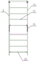
FIG. 1 is a schematic structural diagram of a large-span net rack cornice suspended type automatic moving construction platform of the invention;
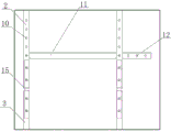
FIG. 2 is a front view of the large-span net rack cornice suspended type automatic moving construction platform in FIG. 1;
FIG. 3 is a side view of a construction platform of the large-span net rack cornice suspended type automatic moving construction platform of FIG. 1;
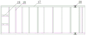
fig. 4 is a top view of a walking frame of the large-span net rack cornice suspended type automatic moving construction platform in fig. 1;
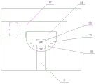
fig. 5 is a partially enlarged view of an angle adjusting structure of the large-span net rack cornice suspended type automatic moving construction platform in fig. 1;
FIG. 6 is an enlarged view of a portion of the large-span net rack cornice suspended type automatic moving construction platform of FIG. 1;
fig. 7 is an enlarged view of a fixing structure of the large-span net rack cornice suspended type automatic moving construction platform in fig. 1.
Reference numerals: 1-a walking frame; 2-a first platform; 3-a second platform; 4-a universal disk; 5-a balancing weight; 6-roof steel skeleton; 7-orbit; 8-walking wheels; 9-a first fixing rod; 10-a first plug hole; 11-adjusting rod; 12-a conditioning aperture; 13-a rectangular frame; 14-erecting a rod; 15-core insert; 16-a connecting rod; 17-side bar; 18-a middle rod; 19-a load-bearing bar; 20-a hinged axis; 21-a fixed part; 22-an adjustment section; 23-a circular hole; 24-a modulus hole; 25-a second fixing bar; 26-a stop; 27-fixing hole.
Detailed Description
The following describes in detail a specific embodiment of a large-span net rack cornice suspended type automatic moving construction platform according to the present invention with reference to the accompanying drawings and specific embodiments:
the structure of the large-span net rack cornice suspension type automatic moving construction platform is shown in figure 1 and comprises a walking frame 1 supported on a roof steel framework 6, walking wheels 8 are fixedly arranged below the walking frame 1, a track 7 is fixedly arranged on the roof steel framework 6, and the walking wheels 8 on the walking frame 1 are in sliding fit with the track 7; still be provided with fixed knot on the walking frame 1 and construct, fixed knot constructs upper portion and operating platform releasable connection, and fixed knot constructs the lower extreme and fixes on roofing steel skeleton 6 in order to realize walking frame 1 for track 7 fixed. A construction platform is hung at one end of the walking frame 1 facing the cornice, a balancing weight 5 is fixedly arranged at one end of the walking frame away from the cornice, and the walking frame 1 can keep balance under the combined action of the balancing weight 5 and the construction platform, so that the walking frame 1 keeps balance when moving along the track 7; an angle adjusting structure is arranged between the walking frame 1 and the construction platform, and the angle adjusting structure can realize angle adjustment of the construction platform relative to the walking frame 1, so that the angle of the construction platform is convenient for workers to construct.
Specifically, as shown in fig. 1 and 5, the angle adjusting structure is a universal disk 4 fixed at one end of the walking frame 1 at the cornice, the universal disk 4 includes blocking pieces arranged in parallel at intervals in front and back, the blocking pieces include a fixing portion 21 and an adjusting portion 22 fixedly connected with the walking frame 1, the adjusting portion 22 is semicircular and is integrally formed with the fixing portion 21, a hinge hole is arranged at the position of the center of circle of the adjusting portion 22, a plurality of round holes 23 are arranged at intervals in the circumferential direction of the adjusting portion 22, the round holes 23 are located on the same circumference with the center of circle of the adjusting portion 22 as the center of circle, the upper end of the construction platform is a hinge end, the hinge end is additionally arranged between the two blocking pieces, hinge holes and through holes are arranged at intervals in the hinge end, and hinge shafts 20 are arranged between the hinge holes of the hinge end and the hinge holes on the blocking pieces, so as to realize the hinge between; when the angle between construction platform for walking frame 1 needs to be adjusted, around articulated shaft 20 rotatory construction platform, also promptly, make construction platform's hinged end rotatory along the clearance between two separation blades, when the through-hole of construction translation platform hinged end was aimed at with different round hole 23 and fixed with the bolt, just can realize the regulation of the contained angle size between construction platform and the walking frame 1, make things convenient for construction platform to satisfy the construction of different inclination's eaves mouth.
The construction platform is structurally shown in fig. 1, 2, 3 and 6, and comprises a first platform 2, a second platform 3 arranged below the first platform 2, and a ferrule 15 inserted between the first platform 2 and the second platform 3, wherein the first platform 2 comprises four upright rods 14 distributed in a rectangular shape and a first plane detachably fixed at the lower parts of the upright rods 14, a row of first insertion holes 10 arranged at intervals are formed in the lower parts of the upright rods 14 of the first platform 2 along the extending direction of the first platform, rectangular frames 13 are arranged at intervals along the extending direction of the upright rods 14 of the first platform 2, and the rectangular frames 13 are welded and fixed with each upright rod 14 of the first platform 2, in this embodiment, the upright rods 14 are hollow rods. The structure of the second platform 3 is the same as that of the first platform 2, and two through holes arranged at intervals are arranged on the upper part of the upright 14 of the second platform 3 along the extending direction. The upper part of the insertion core 15 is provided with a first adaptive hole which is in splicing fit with the first splicing hole 10, and the lower part of the insertion core 15 is provided with a second adaptive hole which is in splicing fit with the second splicing hole; when the device is used, the upper end of the inserting core 15 is inserted into the lower part of the vertical rod 14 of the first platform 2, the first adaptive hole of the inserting core 15 is fixedly connected with the first inserting hole 10 of the vertical rod 14 through a fixing bolt, the lower end of the inserting core 15 is inserted into the upper part of the vertical rod 14 of the second platform 3, and the second adaptive hole of the inserting core 15 is fixedly connected with the second inserting hole of the vertical rod 14 through a fixing bolt. When the distance between the second platform 3 and the first platform 2 needs to be adjusted, the fixing bolt between the upper end of the ferrule 15 and the first platform 2 is detached, the second platform 3 and the ferrule 15 are moved downwards, and the upper end of the ferrule 15 is moved downwards and then fixedly connected with the fixing bolt.
The first plane is as shown in fig. 1 and fig. 2, and includes adjusting rods 11 arranged in parallel at intervals and a connecting rod 16 fixed between the two adjusting rods 11, the adjusting rods 11 and the connecting rod 16 form a rectangular frame, and a flat plate is fixedly arranged on the rectangular frame. The spliced eye articulated connection of the one end of first planar regulation pole 11 and pole setting 14 lower part, adjust the regulation hole 12 that the interval set up along its extending direction offered to the other end of pole 11, the spliced eye on regulation hole 12 and the stand passes through bolt fixed connection, when the spliced eye fixed connection of difference regulation hole 12 and difference, can realize the regulation of the inclination of first plane for the pole setting 14 of first platform 2, thereby when the construction platform slope sets up, the last first plane of construction platform still can keep the level setting with the second plane, thereby make things convenient for stable the standing of operation workman on first plane or second plane.
In this embodiment, the second plane of the second platform 3 and the first plane of the first platform 2 have the same structural configuration, and are not described herein again.
The walking frame 1 has a structure as shown in fig. 1 and 4, the walking frame 1 includes two parallel side rods 17 arranged at intervals and a middle rod 18 vertically fixed between the two side rods 17, the middle rod 18 is provided with a plurality of middle rods 18, and the plurality of middle rods 18 are arranged at intervals in parallel. A bearing rod 19 is fixedly arranged between two adjacent intermediate rods 18 at one end of the walking frame 1 for placing the balancing weight 5, and the bearing rod 19 is vertically and fixedly connected with the intermediate rods 18. The bearing rod 19 is provided with a through hole which penetrates through the bearing rod 19 in the up-down direction, a positioning rod is fixedly arranged on the walking frame 1 through the through hole, the positioning rod is perpendicular to the side rod 17 of the walking frame 1, and the positioning rod penetrates through a through hole in the balancing weight 5 to position the balancing weight 5 on the positioning rod. In this embodiment, the traveling wheels 8 are fixed to one side of the center piece weight 5 of the side bar 17 of the traveling frame 1.
The fixing structure is as shown in fig. 1 and 7, and comprises a first fixing structure and a second fixing structure which are arranged at intervals along the front-back direction, the first fixing structure and the second fixing structure are the same in structure and respectively comprise a first fixing rod 9 extending along the up-down direction and a second fixing rod 25 detachably connected with the first fixing rod 9, a row of module holes 24 arranged at intervals are arranged at the upper part of the first fixing rod 9, a through hole fixedly connected with a module is arranged on the walking frame 1, the second fixing rod 25 is vertically connected with the first fixing rod 9, a stopping part 26 is fixedly arranged at one end of the second fixing rod 25 far away from the first fixing rod 9, the stopping part 26, the second fixing rod 25 and the first fixing rod 9 form a U-shaped structure, the U-shaped structure of the first fixing structure is arranged opposite to the opening of the U-shaped structure of the second fixing structure, so as to realize the hook connection between the first fixing structure and the second fixing structure and the roof steel framework 6, when the first fixing structure and the second fixing structure form a hook, the first fixing rod 9 is in stop fit with the roof steel framework 6, and the walking frame is fixed at a certain position on the track 7.
The second dead lever 25 of fixed knot structure is provided with along its extending direction and to the fixed orifices 27 that set up in pairs, and the setting of fixed orifices 27 can conveniently realize the second dead lever 25 for the regulation of the width between the first dead lever 9, like this if the width of roofing steel skeleton 6 is great, fixed knot structure's U-shaped structure also can carry out the hook with roofing steel skeleton 6. The modulus hole 24 that sets up on the first dead lever 9 can make the distance between second dead lever 25 and the roofing steel skeleton 6 adjust, like this if roofing steel skeleton 6 highly higher, fixed knot constructs's U-shaped structure also can carry out the hook with roofing steel skeleton 6.
During the use, with fixed knot structure with walking frame 1 for 6 fixed connection of roofing steel skeleton, thereby make walking frame 1 fixed at track 7's a certain position, contained angle between inclination adjustment construction platform and the walking frame 1 according to the eaves mouth, and adjust the inclination of the second plane on the inclination of the first plane on the first platform 2 of construction platform and the second platform 3, it is that first plane and second plane all keep the horizontality, make the construction platform can satisfy the construction demand of the great eaves mouth department of inclination, even the construction platform slope sets up, the last first plane of construction platform still keeps the level setting with the second plane. When the construction of this section eaves mouth is accomplished, remove fixed knot to walking frame 1 of fixed knot structure, under the combined action of joining in marriage kind piece and construction platform, walking frame 1 keeps balance, removes walking frame 1, and walking frame 1 takes construction platform to remove, and when reacing next construction position, fixes walking frame 1 once more with fixed knot structure, then carries out the construction of the eaves mouth department of this position.
In the above embodiment, the angle adjusting structure is a universal disc fixed at one end of the walking frame at the cornice, the universal disc includes blocking pieces arranged in parallel in the front and back direction at intervals, each blocking piece includes a fixing portion for being fixedly connected with the walking frame and an adjusting portion fixedly connected with the fixing portion, the adjusting portion is in a semicircular shape, a hinge hole is arranged at the center of a circle of the adjusting portion, at least two adjusting holes are arranged at intervals in the circumferential direction of the adjusting portion, the adjusting holes are located on the same circumference with the center of a circle of the adjusting portion as the center of a circle, the upper end of the construction platform is a hinge end, the hinge end is clamped between the two blocking pieces, the hinge end is provided with hinge holes and through holes arranged at intervals in the vertical direction, the hinge holes are hinged with the hinge holes on the blocking pieces to achieve the hinge joint of the construction platform and the walking frame, and the through holes are; in other embodiments, the universal disk may further include a blocking piece, the blocking piece includes a fixing portion for being fixedly connected to the walking frame and an adjusting portion for being fixedly connected to the fixing portion, the adjusting portion is semicircular, a hinge hole is disposed at a center of the adjusting portion, at least two adjusting holes are circumferentially disposed at intervals in the adjusting portion, and the adjusting holes are located on a same circumference using the center of the adjusting portion as a center of the circle.
In the above embodiment, fixed knot constructs including first fixed knot and the second fixed knot that sets up along fore-and-aft direction interval, and first fixed knot constructs the same with the second fixed knot, all include along the first dead lever that extends from top to bottom direction and with first dead lever releasable connection's second dead lever, in other embodiments, fixed knot constructs can also be the structure of L form, also do not set up the fixed orifices on first dead lever and second dead lever promptly, require the structural standard of roofing steel skeleton and the distance standard between the skeleton this moment.
In the above embodiment, the construction platform includes a first platform, a second platform disposed below the first platform, and a ferrule inserted between the first platform and the second platform; in other embodiments, the construction platform may also include only the first platform.
In the above embodiment, the first platform includes adjusting rods arranged in parallel at intervals and connecting rods fixed between the two adjusting rods, the adjusting rods and the connecting rods form a rectangular frame, a flat plate is fixed on the rectangular frame, one end of each adjusting rod is hinged to the vertical rod, the other end of each adjusting rod is provided with adjusting holes arranged at intervals, the adjusting holes are matched with the first inserting holes on the upright posts to adjust the inclination angle of the first platform, and the structure of the second platform is the same as that of the first platform; in other embodiments, the first plane and the second plane may also be platforms fixedly disposed with respect to the columns, and when the construction platform is disposed obliquely, the first plane and the second plane are also disposed obliquely.
In the above embodiment, the walking frame includes two side rods arranged in parallel at intervals and an intermediate rod vertically fixed between the two side rods, the intermediate rod is arranged in parallel at intervals, and the walking wheel is fixed at one side of the center of the side rod of the walking frame, which is deviated to the counterweight block; in other embodiments, the intermediate bars may also be arranged non-parallel; or the walking wheels are positioned at two sides of the center of the side rod of the walking frame.
In the above embodiment, a bearing rod is fixedly arranged between two adjacent intermediate rods at one end of the walking frame for placing the balancing weight, and the bearing rod is vertically and fixedly connected with the intermediate rods; in other embodiments, the bearing bar may not be provided, and the bearing block is directly fixed to the end of the walking frame away from the cornice.
Claims (9)
1. The utility model provides a large-span rack eaves mouth suspension type automatic movement construction platform, characterized by includes:
a walking frame: supported on the steel skeleton of the roof;
the traveling wheels: the track is fixed below the walking frame and is used for being in sliding fit with a track fixed on a steel skeleton of the roof;
the fixing structure comprises: the upper part of the fixed structure is detachably connected with the operating platform, and the lower end of the fixed structure is fixed on the roof steel framework to fix the walking frame relative to the track;
a balancing weight: the walking frame is arranged at one end of the walking frame far away from the cornice;
a construction platform: hanging at one end of the walking frame at the cornice;
the angle adjusting structure is as follows: the angle adjusting device is arranged between the walking frame and the construction platform to realize the angle adjustment between the construction platform and the walking frame;
adjusting the angle between the construction platform and the walking frame through the angle adjusting structure; and (3) dismantling the fixed structure, keeping the walking frame balanced under the combined action of the balancing weight and the construction platform, and keeping the walking frame balanced when moving along the track.
2. The large-span net rack cornice suspended self-moving construction platform as claimed in claim 1, the angle adjusting structure is a universal disc fixed at one end of the walking frame at the cornice, the universal disc comprises separation blades which are arranged in parallel at intervals in the front and the back, each separation blade comprises a fixed part fixedly connected with the walking frame and an adjusting part fixedly connected with the fixed part, the adjusting part is in a semicircular shape, a hinge hole is arranged at the center of the adjusting part, at least two round holes are arranged at intervals in the circumferential direction of the adjusting part, the round hole is located the same circumference that uses the regulation department centre of a circle as the centre of a circle, construction platform's upper end is the hinged end, and the hinged end clamp is established between two separation blades, and the hinged end sets up hinge hole and the through-hole of interval setting from top to bottom, and the hinge hole is connected in order to realize the articulated of construction platform and walking frame with the hinged hole on the separation blade is articulated, and the through-hole is connected in order to realize the angle modulation between construction platform and the walking frame with the round hole of difference.
3. The large-span net rack cornice suspended self-moving construction platform according to claim 1 or 2, it is characterized in that the fixing structure comprises a first fixing structure and a second fixing structure which are arranged at intervals along the front-back direction, the first fixing structure and the second fixing structure are the same and respectively comprise a first fixing rod extending along the up-down direction and a second fixing rod detachably connected with the first fixing rod, the upper part of the first fixing rod is provided with a row of module holes arranged at intervals, the walking frame is provided with through holes fixedly connected with the module holes, the second fixing rod is perpendicularly connected with the first fixing rod, a blocking portion is fixedly arranged at one end, far away from the first fixing rod, of the second fixing rod, the blocking portion, the second fixing rod and the first fixing rod form a U-shaped structure, fixing holes which are arranged in pairs are formed in the second fixing rod along the extending direction of the second fixing rod, and at least two pairs of fixing holes are formed in the fixing holes so as to conveniently achieve adjustment of the second fixing rod relative to the first fixing rod.
4. The large-span net rack cornice suspended type self-moving construction platform as claimed in claim 1 or 2, wherein the construction platform comprises a first platform, a second platform arranged below the first platform, and a core insert inserted between the first platform and the second platform, a row of first insertion holes are formed at intervals on the lower part of the first platform, a row of second insertion holes are formed at intervals on the upper part of the second support frame, a first adapting hole adapted to the first insertion hole in an insertion manner is formed on the upper part of the core insert, and a second adapting hole adapted to the second insertion hole in an insertion manner is formed on the lower part of the core insert.
5. The large-span net rack cornice suspended type self-moving construction platform as claimed in claim 4, wherein the first platform comprises four upright posts distributed in a rectangular shape and a first plane detachably fixed at lower parts of the upright posts, the first insertion holes are formed at upper parts of the upright posts of the first platform, the second platform comprises four upright posts distributed in a rectangular shape and a second plane detachably fixed at lower parts of the upright posts, and the second insertion holes are formed at lower parts of the upright posts of the second platform.
6. The large-span net rack cornice suspended type self-moving construction platform as claimed in claim 5, wherein rectangular frames are arranged at intervals along the extending direction of the vertical rods of the first platform, and the rectangular frames are welded and fixed with each vertical rod of the first platform; rectangular frames are arranged at intervals along the extension direction of the vertical rods of the second platform, and the rectangular frames are welded and fixed with each vertical rod of the second platform.
7. The large-span net rack cornice suspended type self-moving construction platform as claimed in claim 4, wherein the first platform comprises adjusting rods arranged in parallel at intervals and connecting rods fixed between the two adjusting rods, the adjusting rods and the connecting rods form a rectangular frame, a flat plate is fixed on the rectangular frame, one end of each adjusting rod is hinged to a vertical rod, the other end of each adjusting rod is provided with adjusting holes arranged at intervals, the adjusting holes are matched with the first inserting holes in the upright columns to realize the adjustment of the inclination angle of the first platform, and the second platform has the same structure as the first platform.
8. The large-span net rack cornice suspended type self-moving construction platform as claimed in claim 1 or 2, wherein the walking frame comprises two parallel side rods arranged at intervals and a middle rod vertically fixed between the two side rods, the middle rod is arranged at intervals in parallel, and the walking wheel is fixed at one side of the center of the side rod of the walking frame, which is deviated to the counterweight block.
9. The large-span net rack cornice suspended type self-moving construction platform as claimed in claim 8, wherein a bearing rod is fixedly arranged between two adjacent intermediate rods at one end of the walking frame for placing the balancing weight, and the bearing rod is vertically and fixedly connected with the intermediate rods.
Priority Applications (1)
| Application Number | Priority Date | Filing Date | Title |
|---|---|---|---|
| CN202010308523.8A CN111335615A (en) | 2020-04-18 | 2020-04-18 | Large-span net rack eaves mouth suspension type automatic movement construction platform |
Applications Claiming Priority (1)
| Application Number | Priority Date | Filing Date | Title |
|---|---|---|---|
| CN202010308523.8A CN111335615A (en) | 2020-04-18 | 2020-04-18 | Large-span net rack eaves mouth suspension type automatic movement construction platform |
Publications (1)
| Publication Number | Publication Date |
|---|---|
| CN111335615A true CN111335615A (en) | 2020-06-26 |
Family
ID=71180941
Family Applications (1)
| Application Number | Title | Priority Date | Filing Date |
|---|---|---|---|
| CN202010308523.8A Pending CN111335615A (en) | 2020-04-18 | 2020-04-18 | Large-span net rack eaves mouth suspension type automatic movement construction platform |
Country Status (1)
| Country | Link |
|---|---|
| CN (1) | CN111335615A (en) |
Cited By (2)
| Publication number | Priority date | Publication date | Assignee | Title |
|---|---|---|---|---|
| CN114197847A (en) * | 2021-11-25 | 2022-03-18 | 中建八局第二建设有限公司 | Construction method of assembled roof cornice modeling curtain wall |
| CN115126263A (en) * | 2022-08-11 | 2022-09-30 | 甘肃盛宏建筑工程有限责任公司 | Assembly type guide rail unloading platform and working method |
Citations (6)
| Publication number | Priority date | Publication date | Assignee | Title |
|---|---|---|---|---|
| CN201671315U (en) * | 2010-05-21 | 2010-12-15 | 上海外高桥造船有限公司 | Adjustable scaffold |
| CN205713026U (en) * | 2016-06-17 | 2016-11-23 | 中建八局第二建设有限公司 | One can be walked cornice high-altitude operation vehicle |
| CN206428956U (en) * | 2017-01-06 | 2017-08-22 | 北京城建八建设发展有限责任公司 | Driven hanging basket and its fixing device |
| CN108708542A (en) * | 2018-08-01 | 2018-10-26 | 中国新兴建筑工程有限责任公司 | Feasible walking aerial working suspension platform and construction method for anti-collision wall construction |
| CN109958273A (en) * | 2019-03-26 | 2019-07-02 | 中国五冶集团有限公司 | Corner cantilevered structure |
| US20190352920A1 (en) * | 2018-05-18 | 2019-11-21 | John Robert Salyer | Modular Fall Protection System |
-
2020
- 2020-04-18 CN CN202010308523.8A patent/CN111335615A/en active Pending
Patent Citations (6)
| Publication number | Priority date | Publication date | Assignee | Title |
|---|---|---|---|---|
| CN201671315U (en) * | 2010-05-21 | 2010-12-15 | 上海外高桥造船有限公司 | Adjustable scaffold |
| CN205713026U (en) * | 2016-06-17 | 2016-11-23 | 中建八局第二建设有限公司 | One can be walked cornice high-altitude operation vehicle |
| CN206428956U (en) * | 2017-01-06 | 2017-08-22 | 北京城建八建设发展有限责任公司 | Driven hanging basket and its fixing device |
| US20190352920A1 (en) * | 2018-05-18 | 2019-11-21 | John Robert Salyer | Modular Fall Protection System |
| CN108708542A (en) * | 2018-08-01 | 2018-10-26 | 中国新兴建筑工程有限责任公司 | Feasible walking aerial working suspension platform and construction method for anti-collision wall construction |
| CN109958273A (en) * | 2019-03-26 | 2019-07-02 | 中国五冶集团有限公司 | Corner cantilevered structure |
Cited By (4)
| Publication number | Priority date | Publication date | Assignee | Title |
|---|---|---|---|---|
| CN114197847A (en) * | 2021-11-25 | 2022-03-18 | 中建八局第二建设有限公司 | Construction method of assembled roof cornice modeling curtain wall |
| CN114197847B (en) * | 2021-11-25 | 2023-03-21 | 中建八局第二建设有限公司 | Construction method of assembled roof cornice modeling curtain wall |
| CN115126263A (en) * | 2022-08-11 | 2022-09-30 | 甘肃盛宏建筑工程有限责任公司 | Assembly type guide rail unloading platform and working method |
| CN115126263B (en) * | 2022-08-11 | 2023-12-12 | 甘肃盛宏建筑工程有限责任公司 | Assembled guide rail unloading platform and working method |
Similar Documents
| Publication | Publication Date | Title |
|---|---|---|
| CA2498870C (en) | Suspended cable scaffold assembly | |
| AU2008348861B2 (en) | Vertical frame intended for the construction of a frame stanchion, a supporting frame and/or a supporting frame tower | |
| CN111335615A (en) | Large-span net rack eaves mouth suspension type automatic movement construction platform | |
| CN207314789U (en) | A kind of safety building scaffold easy to remove | |
| CN208668903U (en) | A kind of fabricated scaffold | |
| CN212053667U (en) | Building outer wall construction scaffold convenient to installation | |
| CN210216169U (en) | A suspension type handling frame for construction outside concrete barrier | |
| CN209494204U (en) | Suspension type steel ladder | |
| CN112627045A (en) | Hang basket template scissors cat ladder | |
| CN209194967U (en) | A kind of construction combined type hanging cage | |
| CN217897219U (en) | Overhanging type scaffold suitable for curtain wall indoor installation | |
| CN218541448U (en) | Attached lifting scaffold for high-rise building construction | |
| CN220599110U (en) | Movable bridge type operation platform | |
| CN111945561A (en) | Special-shaped cable tower decorative plate installation device and construction method | |
| CN214989852U (en) | Internal-climbing and external-hanging tower type supporting device | |
| CN212897468U (en) | Detachable scaffold for building site | |
| CN115450135A (en) | Bridge construction hanging flower basket | |
| CN219196682U (en) | Roof flower stand hanging basket system | |
| CN219411747U (en) | Safe type building construction frame | |
| CN215631516U (en) | Hanging flower basket device is used in construction of roof slope roofing platform curtain | |
| CN218060693U (en) | Assembled steel construction building | |
| CN220226207U (en) | Anti-falling device for steel structure engineering construction | |
| CN214834625U (en) | Wall-riding type hanging basket suspension device | |
| CN220685792U (en) | Adjustable temporary supporting device | |
| CN212053700U (en) | Keel plate connecting device for attached lifting scaffold |
Legal Events
| Date | Code | Title | Description |
|---|---|---|---|
| PB01 | Publication | ||
| PB01 | Publication | ||
| SE01 | Entry into force of request for substantive examination | ||
| SE01 | Entry into force of request for substantive examination | ||
| RJ01 | Rejection of invention patent application after publication |
Application publication date: 20200626 |
|
| RJ01 | Rejection of invention patent application after publication |