CN111284749B - Electric wire winding device - Google Patents
Electric wire winding device Download PDFInfo
- Publication number
- CN111284749B CN111284749B CN202010244291.4A CN202010244291A CN111284749B CN 111284749 B CN111284749 B CN 111284749B CN 202010244291 A CN202010244291 A CN 202010244291A CN 111284749 B CN111284749 B CN 111284749B
- Authority
- CN
- China
- Prior art keywords
- shell
- fixed
- electric wire
- plate
- bevel gear
- Prior art date
- Legal status (The legal status is an assumption and is not a legal conclusion. Google has not performed a legal analysis and makes no representation as to the accuracy of the status listed.)
- Expired - Fee Related
Links
- 238000004804 winding Methods 0.000 title claims abstract description 53
- 239000002390 adhesive tape Substances 0.000 claims abstract description 29
- 238000003825 pressing Methods 0.000 claims description 5
- 230000006835 compression Effects 0.000 claims description 4
- 238000007906 compression Methods 0.000 claims description 4
- 210000001503 joint Anatomy 0.000 abstract description 3
- 230000037303 wrinkles Effects 0.000 abstract description 2
- 238000000034 method Methods 0.000 description 3
- 230000008719 thickening Effects 0.000 description 3
- 230000009471 action Effects 0.000 description 2
- 238000010923 batch production Methods 0.000 description 2
- 238000006073 displacement reaction Methods 0.000 description 2
- 238000004519 manufacturing process Methods 0.000 description 2
- 230000008569 process Effects 0.000 description 2
- 238000005299 abrasion Methods 0.000 description 1
- 230000007547 defect Effects 0.000 description 1
- 230000006872 improvement Effects 0.000 description 1
- 238000011065 in-situ storage Methods 0.000 description 1
- 239000000463 material Substances 0.000 description 1
- 229920006280 packaging film Polymers 0.000 description 1
- 239000012785 packaging film Substances 0.000 description 1
- 238000004806 packaging method and process Methods 0.000 description 1
- 238000012856 packing Methods 0.000 description 1
Images


Classifications
-
- B—PERFORMING OPERATIONS; TRANSPORTING
- B65—CONVEYING; PACKING; STORING; HANDLING THIN OR FILAMENTARY MATERIAL
- B65B—MACHINES, APPARATUS OR DEVICES FOR, OR METHODS OF, PACKAGING ARTICLES OR MATERIALS; UNPACKING
- B65B27/00—Bundling particular articles presenting special problems using string, wire, or narrow tape or band; Baling fibrous material, e.g. peat, not otherwise provided for
- B65B27/10—Bundling rods, sticks, or like elongated objects
- B65B27/105—Bundling rods, sticks, or like elongated objects by means of adhesive tape
Abstract
The invention provides an electric wire winding device which effectively solves the problems that the winding density and thickness are uneven, the winding density cannot be adjusted according to the actual needs on site, air bubbles are easy to wrinkle, the hidden danger of joint damage exists, and an adhesive tape cannot be wound at any position when the existing electric wire winding device is used for winding an electric wire; the technical scheme includes that the device comprises a shell, wherein a first rotating wheel is arranged in the shell, a first bevel gear is arranged on the first rotating wheel, a rotating shaft is arranged in the shell, a second bevel gear is meshed with the first bevel gear, a through hole is formed in the left side plate of the shell, an arc-shaped plate is arranged in the through hole, a large gear is arranged on the left side wall of the shell, one large gear is coaxially fixed with the rotating shaft, a plurality of small gears are arranged between the large gears, gear teeth are arranged on the outer side of the right end of the arc-shaped plate, a fan-shaped bulge is arranged on the outer side of the left end of the arc-shaped plate, and an electrical tape is arranged on the left end face of the fan-shaped bulge; a hollow cylinder is fixed on the left side of the shell, a pressure plate is arranged in the hollow cylinder, and a pressure spring is connected between the upper end of the pressure plate and the upper end of the hollow cylinder.
Description
Technical Field
The invention relates to the technical field of wire winding and packaging, in particular to a wire winding device.
Background
In the prior art, the end parts of electric wires are connected with connectors, especially various power lines, in order to protect the connectors, people usually wind more adhesive tapes or packing materials at the connectors than at other places, and manufacturers only pack the end parts of the electric wires and directly coil and seal bags at other parts; still other production identifiers need to be affixed to the middle of the wire. However, in the prior art, some portable tools are adopted to drive the adhesive tape to wind, but there are some problems in practical use, for example, CN106532588B a tape winding device discloses a handheld portable tool, but such a tool mainly solves the problem that the adhesive tape does not freely shake during winding, but still needs to be repeatedly taken, pulled, placed and taken, the operation is still tedious, the advancing distance of each circle of the adhesive tape cannot be grasped, compared with manual winding, the tool has little improvement on efficiency and quality, and the labor amount is still large.
In addition, a part of the electric wires are driven by a motor to be wound, the electric wires are pulled at a constant speed through a winch, the winding action is driven by the other motor, if the electric wires need to be wound in an encrypted mode, only the output rotating speed of one of the motors can be changed, but the electric wires are only suitable for small-batch production, for large-batch production, the mode is obviously too troublesome and the output rotating speed of the motor is frequently changed, the damage to the motor is also large, and bubble folds (such as wrapping wires at wire connection positions, and the folds are required to be avoided as much as possible in principle) are easily caused to influence the overall attractiveness, so that the motor can effectively save manpower, the winding quality cannot be guaranteed, and the requirement for local encryption, thickening and winding of the electric wires cannot be met.
In summary, the following drawbacks exist in the prior art:
1. the end part of the wire cannot be encrypted and wound according to timely requirements, and the end part joint of the wire cannot be protected;
2. the plurality of motors work in a cooperative mode, the local part of the wire needs to be encrypted, thickened and wound by frequently controlling the output speed of each motor, the operation is troublesome, and the motors are easily damaged;
3. the winding encryption degree cannot be controlled at will, and the field personal cannot be adjusted at will;
4. the adhesive tape with the mark cannot be wound on any local area of the adhesive tape as required.
Disclosure of Invention
Aiming at the situation, the invention provides the wire winding device to overcome the defects of the prior art, and the wire winding device effectively solves the problems that the winding density and thickness are uneven, the winding density cannot be adjusted according to the actual needs on site, air bubbles are easy to wrinkle, the hidden danger of joint damage exists, and an adhesive tape cannot be wound at any position in the conventional wire winding process.
The technical scheme includes that the wire winding device comprises a rectangular shell with a downward opening, a first rotating wheel capable of rotating is arranged in the shell, the lower end of the first rotating wheel presses an electric wire, the electric wire can drive the first rotating wheel to rotate when the electric wire moves left and right relative to the shell, a first bevel gear is coaxially fixed on the first rotating wheel, a horizontal rotating shaft is arranged in the shell, the left end of the rotating shaft is rotationally fixed with the shell, a second bevel gear coaxial with the rotating shaft is meshed on the first bevel gear, and the second bevel gear can drive the rotating shaft to rotate; the left side plate of the shell is provided with a horizontal through hole, an arc-shaped plate which is coaxial with the through hole and can rotate is arranged in the through hole, the right end of the arc-shaped plate is arranged in the cavity of the shell, the left side wall of the shell is provided with a plurality of large gears which can rotate, one of the large gears is coaxially fixed with a rotating shaft, a plurality of small gears are arranged between the large gears, the rotating shaft can drive the large gears to simultaneously rotate in the same direction by rotating, the outer side of the right end of the arc-shaped plate is provided with gear teeth which are meshed with the large gears, the outer side of the left end;
the casing left side be fixed with the level form and with the hollow cylinder that the through-hole corresponds, there is the clamp plate of level form in the hollow cylinder, be connected with the pressure spring between clamp plate upper end and the hollow cylinder upper end, the electric wire is by the left right side through hollow cylinder, arc, first runner lower extreme in proper order.
The wire joint winding device is ingenious in structure, winding density and winding thickness of the adhesive tape can be effectively prevented from being effectively controlled, control and adjustment of the winding density and the winding thickness can be achieved through manual intervention in a local area according to actual needs, adjustment is convenient, thickening and encryption winding of the wire joint can be achieved, and operation is convenient.
Drawings
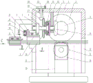
FIG. 1 is a front cross-sectional view of the present invention.
FIG. 2 is a side cross-sectional view of the present invention.
Fig. 3 is a view from a in fig. 1.
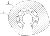
Fig. 4 is a view from direction B of fig. 1.
Fig. 5 is a view from direction C of fig. 1.
Fig. 6 is a view from direction D of fig. 1.
Fig. 7 is a schematic view of the housing structure of the present invention.
FIG. 8 is a schematic view of the structure of the flat plate and the components thereon.
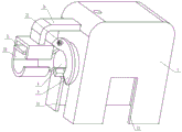
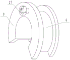
FIG. 9 is a schematic view of the arc plate and the fan-shaped protrusion.
Fig. 10 is a schematic view of the connection between the arc plate and the side plate of the housing.
Detailed Description
The following description will explain embodiments of the present invention in further detail with reference to the accompanying drawings.
As shown in fig. 1 to 10, the invention includes a rectangular housing 1 with a downward opening, a rotatable first rotating wheel 2 is arranged in the housing 1, an electric wire is pressed at the lower end of the first rotating wheel 2, the electric wire can drive the first rotating wheel 2 to rotate when the electric wire moves left and right relative to the housing 1, a first bevel gear 3 is coaxially fixed on the first rotating wheel 2, a horizontal rotating shaft 4 is arranged in the housing 1, the left end of the rotating shaft 4 is rotationally fixed with the housing 1, a second bevel gear 5 coaxial with the rotating shaft 4 is engaged on the first bevel gear 3, and the rotating shaft 4 can be driven to rotate by the second bevel gear 5; a horizontal through hole is formed in the left side plate of the shell 1, an arc-shaped plate 6 which is coaxial with the through hole and can rotate is arranged in the through hole, the right end of the arc-shaped plate 6 is arranged in the cavity of the shell 1, a plurality of large gears 7 which can rotate are arranged on the left side wall of the shell 1, one large gear 7 is coaxially fixed with a rotating shaft 4, a plurality of small gears 8 are arranged between the large gears 7, the rotating shaft 4 can drive the large gears 7 to rotate in the same direction at the same time by rotating, gear teeth meshed with the large gears 7 are arranged on the outer side of the right end of the arc-shaped plate 6, a fan-shaped bulge 9 is arranged on the outer side of the left end of the arc-shaped bulge 9, and an electrical tape is arranged on the left end surface of the fan-shaped bulge 9;
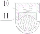
the left side of the shell 1 is fixed with a horizontal hollow cylinder 10 corresponding to the through hole, a horizontal pressing plate 11 is arranged in the hollow cylinder 10, a pressure spring is connected between the upper end of the pressing plate 11 and the upper end of the hollow cylinder 10, and the electric wire sequentially passes through the lower ends of the hollow cylinder 10, the arc-shaped plate 6 and the first rotating wheel 2 from left to right.
In order to control the winding thickness and density, a vertical plate 12 is arranged in the housing 1, the upper end of the vertical plate 12 is fixed with the housing 1, a central shaft 14 of the second bevel gear 5 is rotationally fixed on the vertical plate 12, a planetary gear train is arranged between the left end of the central shaft 14 and the right end of the rotating shaft 4, wherein outer ring gear 13 is fixed with center pin 14, the sun gear is fixed with pivot 4, planet carrier 15 suit is on pivot 4, be fixed with third bevel gear 16 coaxial with pivot 4 on the planet carrier 15, third bevel gear 16 upper end meshing has can level pivoted fourth bevel gear 17, fourth bevel gear 17 upper end is fixed with vertical axis 18, vertical axis 18 upper end runs through the side plate on the casing 1 and arranges the casing 1 outside in, vertical axis 18 upper end is fixed with carousel 19, there is vertical screw hole that has run through on the carousel 19, the internal screw thread has screwed up housing screw 20, it can fix carousel 19 on casing 1 to twist up housing screw 20.
In order to wind the local part of the electric wire conveniently, a vertical first vertical groove 21 is formed in the left side plate of the shell 1, the upper end of the first vertical groove 21 is communicated with the through hole, a second vertical groove 22 corresponding to the first vertical groove 21 is formed in the right side plate of the shell 1, and the first vertical groove 21 and the second vertical groove 22 penetrate through the lower end face of the shell 1.
In order to ensure that the electric wire drives the first rotating wheel 2 to rotate, the front side plate and the rear side plate of the shell 1 are respectively provided with a sliding groove 23 which is vertically arranged, each sliding groove 23 is internally provided with a rectangular block 24 which can slide up and down along the sliding groove, the lower side of the first rotating wheel 2 is provided with a second rotating wheel 25 which can rotate, the second rotating wheel 25 and the rectangular block 24 are fixed together in a rotating way, the electric wire can be tightly pressed by the first rotating wheel 2 and the second rotating wheel 25, a horizontal flat plate is arranged below the shell 1, and the rectangular block 24 is fixed on the flat plate.
In order to ensure that the electric wire passes between the first rotating wheel 2 and the second rotating wheel 25, two ends of the second rotating wheel 25 are provided with annular bulges, and the lower end of the first rotating wheel 2 is arranged between the two annular bulges.
In order to fix the hollow cylinder 10, an L-shaped connecting rod 26 is fixed at the upper end of the hollow cylinder 10, and the other end of the connecting rod 26 is fixed with the shell 1.
In order to install the adhesive tape, 9 left end faces of fan-shaped protrusion on be fixed with cylinder shell 27, cylinder shell 27 central line is the level form, the adhesive tape suit is on cylinder shell 27, there is rather than coaxial disc 28 in the cylinder shell 27, it has a plurality of pins to run through on the lateral wall in the cylinder shell 27, cylinder shell 27 is arranged in to pin one end, the pin is arranged in one of cylinder shell 27 and is served and have annular arch, be connected with the pressure spring between annular arch and the cylinder shell 27 lateral wall, the pressure spring makes disc 28 and pin keep in contact, the cylinder shell 27 outside is arranged in to the pin other end, disc 28 has a plurality ofly all around and the wedge of pin one-to-one, disc 28 rotates and can drive the pin outwards withstands the adhesive tape.
In order to reduce the abrasion between the arc-shaped plate 6 and the side wall of the through hole, the side wall of the through hole and the arc-shaped plate 6 are spaced, a plurality of rollers are uniformly distributed in the space, the rollers are hinged with the side wall of the through hole, and one side of each roller is in contact with the arc-shaped plate 6.
It is worth noting that, in order to facilitate the electric wire to enter the hollow cylinder 10, a transverse groove which is communicated with the left and the right is arranged on the front side plate of the hollow cylinder 10, and the electric wire can enter the hollow cylinder 10 through the transverse groove; there is the cylinder piece disc 28 left side, and cylinder piece left end runs through cylinder shell 27 left side board and arranges the cylinder shell 27 outside in, rotates the cylinder piece and can drive disc 28 and rotate, and when the pin outwards removed and contacted the sticky tape, the pin provided a frictional force for the sticky tape for can not drop at winding in-process sticky tape.
In the initial state, the compression screw 20 on the rotary disc 19 makes the rotary disc 19 fixed, at this time, the third bevel gear 16 is fixed by the fourth bevel gear 17, and the planet carrier 15 in the planetary gear train is fixed. When in use, the flat plate is pulled downwards, the flat plate draws the second rotating wheel 25 out of the shell 1 through the rectangular block 24, the electric wire penetrates through the device from left to right, the electric wire passes through the device at a constant speed under the driving of the winch, the electric wire is placed in the first vertical groove 21 and the second vertical groove 22 at the moment, the electric wire is placed in the hollow cylinder 10 through the transverse groove, the pressing plate 11 presses the electric wire at the lower end in the cavity of the hollow cylinder 10 under the action of the spring, then the second rotating wheel 25 moves upwards until the second rotating wheel 25 and the first rotating wheel 2 tightly press the electric wire, the adhesive tape roll is sleeved on the cylindrical shell 27, the disc 28 is screwed to enable the pins to move outwards and prop against the adhesive tape roll, one end of the adhesive tape is pre-adhered or wound on the electric wire, the device is fixed on a workbench or the ground so as not to move freely, at the constant speed, the wire is pulled by the winch at the constant speed, the electric wire drives the first rotating wheel 2 to rotate the second rotating gear 5 through the first bevel gear 3, the center shaft 14 of the second bevel gear 5 drives the outer gear ring 13 to rotate, and the planet carrier 15 at the moment is fixed, so the sun gear rotates, the sun gear drives the big gear 7 fixed with the sun gear through the rotating shaft 4 to rotate, the big gear 7 drives the other big gears 7 to rotate in the same direction through the small gear 8, the big gear 7 is meshed with the gear teeth on the arc-shaped plate 6, so that the arc-shaped plate 6 rotates in the through hole, the arc-shaped plate 6 rotates to drive the adhesive tape to rotate around the wire, and the adhesive tape winds the wire in the rotating process.
When the winding density is increased or the thickness of the adhesive tape is increased in a local place, firstly, the winding machine is kept to pull the electric wire at a constant speed, the compression screw 20 on the rotary table 19 is loosened, then the shell 1 and the flat plate are pinched by one hand, the rotary table 19 is rotated by the other hand, the rotary table 19 drives the third bevel gear 16 to rotate through the fourth bevel gear 17, at the moment, the planet carrier 15 and the outer gear ring 13 are simultaneously input for the planetary gear train, the output rotating speed of the sun gear is increased, and therefore, the rotating speed of the rotary table 19 can be manually controlled at will to control the arbitrary winding density and thickness of the adhesive tape; if in-situ winding is required, this can be achieved by simply turning off the winch and turning the turntable 19.
If the local area on the electric wire needs to be wound or stuck with the adhesive tape with the mark, the device is firmly fixed at a certain position, then the electric wire is clamped between the hollow cylinder 10, the arc-shaped plate 6, the first rotating wheel 2 and the second rotating wheel 25 in sequence, and then the electric wire is pulled at a constant speed, so that the local area of the electric wire can be wound.
The invention has the outstanding advantages and remarkable progress that:
1. when the winding device is used, the first rotating wheel 2 is rotated by utilizing the relative displacement of the electric wire and the shell 1, and then the arc-shaped plate 6 provided with the adhesive tape is driven to rotate around the electric wire by utilizing the plurality of the large gears 7, so that the winding of the electric wire is realized.
2. According to the invention, the control of the winding density and thickness of the adhesive tape is realized by controlling the state of the planet carrier 15 by utilizing the structural characteristics of the planetary gear train, the carrying is convenient, the adjustment can be carried out according to the actual needs on site, the adjustment is convenient, the application range is wide, even if no displacement exists between the electric wire and the shell 1, the winding can be realized in the same place of the electric wire, and the adaptability is wide.
3. According to the invention, the adhesive tape is replaced by the packaging film, so that a plurality of wires can be packaged and packed into a bundle, strips can be wound and packed, and joints at the ends of the wires can be specially thickened, encrypted and wound to realize local winding protection.
4. The invention can adapt to common winding operation, and can quickly wind the adhesive tape with the mark on any local area of the adhesive tape according to the requirement, thereby meeting the production requirement of a factory.
The wire joint winding device is ingenious in structure, winding density and winding thickness of the adhesive tape can be effectively prevented from being effectively controlled, control and adjustment of the winding density and the winding thickness can be achieved through manual intervention in a local area according to actual needs, adjustment is convenient, thickening and encryption winding of the wire joint can be achieved, and operation is convenient.
Claims (7)
1. An electric wire winding device is characterized by comprising a rectangular shell (1) with a downward opening, wherein a first rotating wheel (2) capable of rotating is arranged in the shell (1), an electric wire is pressed at the lower end of the first rotating wheel (2), the electric wire can drive the first rotating wheel (2) to rotate when moving left and right relative to the shell (1), a first bevel gear (3) is coaxially fixed on the first rotating wheel (2), a horizontal rotating shaft (4) is arranged in the shell (1), the left end of the rotating shaft (4) is rotationally fixed with the shell (1), a second bevel gear (5) coaxial with the rotating shaft (4) is meshed on the first bevel gear (3), and the rotating shaft (4) can be driven to rotate by the second bevel gear (5); a horizontal through hole is formed in the left side plate of the shell (1), an arc-shaped plate (6) which is coaxial with the through hole and can rotate is arranged in the through hole, the right end of the arc-shaped plate (6) is arranged in the cavity of the shell (1), a plurality of large gears (7) which can rotate are arranged on the left side wall of the shell (1), one large gear (7) is coaxially fixed with the rotating shaft (4), a plurality of small gears (8) are arranged between the large gears (7), the rotating shaft (4) can drive the large gears (7) to simultaneously rotate in the same direction by rotating, gear teeth meshed with the large gears (7) are arranged on the outer side of the right end of the arc-shaped plate (6), a fan-shaped bulge (9) is arranged on the outer side of the left end of the arc-shaped plate (6), and an electrical adhesive tape is arranged on the left end face of the fan-shaped bulge (9);
a horizontal hollow cylinder (10) corresponding to the through hole is fixed on the left side of the shell (1), a horizontal pressing plate (11) is arranged in the hollow cylinder (10), a pressure spring is connected between the upper end of the pressing plate (11) and the upper end of the hollow cylinder (10), and the electric wire sequentially passes through the hollow cylinder (10), the arc-shaped plate (6) and the lower end of the first rotating wheel (2) from left to right;
a vertical plate (12) is arranged in the shell (1), the upper end of the vertical plate (12) is fixed with the shell (1), a central shaft (14) of a second bevel gear (5) is rotationally fixed on the vertical plate (12), a planetary gear train is arranged between the left end of the central shaft (14) and the right end of a rotating shaft (4), an outer gear ring (13) is fixed with the central shaft (14), a sun gear is fixed with the rotating shaft (4), a planet carrier (15) is sleeved on the rotating shaft (4), a third bevel gear (16) coaxial with the rotating shaft (4) is fixed on the planet carrier (15), a fourth bevel gear (17) capable of horizontally rotating is meshed at the upper end of the third bevel gear (16), a vertical shaft (18) is fixed at the upper end of the fourth bevel gear (17), the upper end of the vertical shaft (18) penetrates through the upper side plate of the shell (1) and is arranged outside the shell (1), a turntable (19) is fixed at the upper end of the vertical shaft (18), a vertical threaded hole penetrates through the rotary table (19), a compression screw (20) is screwed in the threaded hole, and the rotary table (19) can be fixed on the shell (1) by screwing the compression screw (20).
2. The electric wire winding device according to claim 1, wherein a vertical first vertical groove (21) is formed in the left side plate of the housing (1), the upper end of the first vertical groove (21) is communicated with the through hole, a second vertical groove (22) corresponding to the first vertical groove (21) is formed in the right side plate of the housing (1), and the first vertical groove (21) and the second vertical groove (22) penetrate through the lower end face of the housing (1).
3. The electric wire winding device according to claim 1, wherein the front and rear side plates of the housing (1) are provided with vertically arranged sliding grooves (23), each sliding groove (23) is internally provided with a rectangular block (24) capable of sliding up and down along the sliding groove, a second rotating wheel (25) capable of rotating is arranged at the lower side of the first rotating wheel (2), the second rotating wheel (25) and the rectangular block (24) are fixed together in a rotating manner, the electric wire can be tightly pressed by the first rotating wheel (2) and the second rotating wheel (25), a horizontal flat plate is arranged below the housing (1), and the rectangular block (24) is fixed on the flat plate.
4. A wire winding device according to claim 3, wherein the second pulley (25) has annular projections at both ends thereof, and the lower end of the first pulley (2) is interposed between the annular projections.
5. An electric wire winding device according to claim 1, wherein an L-shaped connecting rod (26) is fixed to the upper end of the hollow cylinder (10), and the other end of the connecting rod (26) is fixed to the housing (1).
6. The electric wire winding device according to claim 1, wherein a cylindrical shell (27) is fixed on the left end face of the fan-shaped protrusion (9), the center line of the cylindrical shell (27) is horizontal, the adhesive tape is sleeved on the cylindrical shell (27), a disc (28) coaxial with the cylindrical shell (27) is arranged in the cylindrical shell (27), a plurality of pins penetrate through the side wall in the cylindrical shell (27), one end of each pin is arranged in the cylindrical shell (27), an annular protrusion is arranged at one end of each pin arranged in the cylindrical shell (27), a pressure spring is connected between each annular protrusion and the side wall of the cylindrical shell (27) and enables the disc (28) to be in contact with the corresponding pin, the other end of each pin is arranged on the outer side of the cylindrical shell (27), a plurality of wedge-shaped blocks corresponding to the pins in a one-to-one mode are arranged on the periphery of the disc (28), and the disc (28) can rotate to drive the pins to outwards support the adhesive tape.
7. The wire winding device according to claim 1, wherein a space is provided between the side wall of the through hole and the arc-shaped plate (6), a plurality of rollers are uniformly distributed in the space, the rollers are hinged with the side wall of the through hole, and one side of each roller is in contact with the arc-shaped plate (6).
Priority Applications (1)
| Application Number | Priority Date | Filing Date | Title |
|---|---|---|---|
| CN202010244291.4A CN111284749B (en) | 2020-03-31 | 2020-03-31 | Electric wire winding device |
Applications Claiming Priority (1)
| Application Number | Priority Date | Filing Date | Title |
|---|---|---|---|
| CN202010244291.4A CN111284749B (en) | 2020-03-31 | 2020-03-31 | Electric wire winding device |
Publications (2)
| Publication Number | Publication Date |
|---|---|
| CN111284749A CN111284749A (en) | 2020-06-16 |
| CN111284749B true CN111284749B (en) | 2021-08-03 |
Family
ID=71022232
Family Applications (1)
| Application Number | Title | Priority Date | Filing Date |
|---|---|---|---|
| CN202010244291.4A Expired - Fee Related CN111284749B (en) | 2020-03-31 | 2020-03-31 | Electric wire winding device |
Country Status (1)
| Country | Link |
|---|---|
| CN (1) | CN111284749B (en) |
Families Citing this family (1)
| Publication number | Priority date | Publication date | Assignee | Title |
|---|---|---|---|---|
| CN114883057B (en) * | 2022-06-10 | 2023-08-11 | 国网河南省电力公司三门峡供电公司 | Automatic winding machine for insulating tape |
Citations (5)
| Publication number | Priority date | Publication date | Assignee | Title |
|---|---|---|---|---|
| JPH07304571A (en) * | 1994-05-11 | 1995-11-21 | Hisao Aoshima | Tape winding binding device for electric wire |
| CN205820547U (en) * | 2016-06-17 | 2016-12-21 | 青岛三汇橡胶机械制造有限公司 | A kind of steel wire winding speed, angle robot control system(RCS) |
| CN107601184A (en) * | 2017-09-28 | 2018-01-19 | 国网山东省电力公司经济技术研究院 | A kind of cable aluminium strip wrapping machine provided with multiple bay structure |
| CN108963859A (en) * | 2018-07-09 | 2018-12-07 | 国网山东省电力公司莱芜供电公司 | A kind of insulating tape automatic winding apparatus |
| CN109052074A (en) * | 2018-08-28 | 2018-12-21 | 徐州市永拓机械科技有限公司 | A kind of device and winding method for harness automatic winding adhesive tape |
-
2020
- 2020-03-31 CN CN202010244291.4A patent/CN111284749B/en not_active Expired - Fee Related
Patent Citations (5)
| Publication number | Priority date | Publication date | Assignee | Title |
|---|---|---|---|---|
| JPH07304571A (en) * | 1994-05-11 | 1995-11-21 | Hisao Aoshima | Tape winding binding device for electric wire |
| CN205820547U (en) * | 2016-06-17 | 2016-12-21 | 青岛三汇橡胶机械制造有限公司 | A kind of steel wire winding speed, angle robot control system(RCS) |
| CN107601184A (en) * | 2017-09-28 | 2018-01-19 | 国网山东省电力公司经济技术研究院 | A kind of cable aluminium strip wrapping machine provided with multiple bay structure |
| CN108963859A (en) * | 2018-07-09 | 2018-12-07 | 国网山东省电力公司莱芜供电公司 | A kind of insulating tape automatic winding apparatus |
| CN109052074A (en) * | 2018-08-28 | 2018-12-21 | 徐州市永拓机械科技有限公司 | A kind of device and winding method for harness automatic winding adhesive tape |
Also Published As
| Publication number | Publication date |
|---|---|
| CN111284749A (en) | 2020-06-16 |
Similar Documents
| Publication | Publication Date | Title |
|---|---|---|
| CN207057308U (en) | Steel roll opener | |
| CN111284749B (en) | Electric wire winding device | |
| CN108483146B (en) | A kind of electrical adhesive tape twines adhesive dispenser | |
| CN113233225A (en) | Automatic wrapping and rolling equipment for preservative film | |
| CN103010806B (en) | A kind of banding machine | |
| CN108438994A (en) | A kind of small-sized rotary type tower double-station automatic deploying and retracting winding apparatus | |
| CN205916837U (en) | Cable tractor and install cable production line of this tractor | |
| CN111326994B (en) | Conductor wire packing wind | |
| CN212101434U (en) | Constant tension stable uninterrupted paying-off equipment | |
| CN215437061U (en) | Cable coating machine | |
| CN203726904U (en) | Compositing blanking machine of paperboards | |
| CN206327960U (en) | A kind of coiled material automatic splicing device | |
| CN214053514U (en) | Winding displacement cutting equipment | |
| CN214043249U (en) | Can guarantee high-efficient electric wire rubber coating device of electric wire finished product quality | |
| CN212374493U (en) | Packaging film feeding adjusting device | |
| CN104441934B (en) | Shaftless friction type energy-saving roll bending winding/unwinding device | |
| CN217456437U (en) | Packaging plastic packaging film winding machine | |
| CN108454929B (en) | Material roll packing device of strip mill | |
| CN113213226B (en) | Full-automatic rolling device for PVC soft board production | |
| CN217624276U (en) | Automatic packaging equipment for elevator sheet metal parts | |
| CN212324442U (en) | Electrostatic discharge device for PE film | |
| CN216301725U (en) | Packing apparatus is used in production of medical bandage | |
| CN214165509U (en) | Carton equipment for packing with dust removal function | |
| CN218057899U (en) | Rolling machine of convenient operation | |
| CN219525801U (en) | Rolling rubberizing device and equipment |
Legal Events
| Date | Code | Title | Description |
|---|---|---|---|
| PB01 | Publication | ||
| PB01 | Publication | ||
| SE01 | Entry into force of request for substantive examination | ||
| SE01 | Entry into force of request for substantive examination | ||
| GR01 | Patent grant | ||
| GR01 | Patent grant | ||
| CF01 | Termination of patent right due to non-payment of annual fee |
Granted publication date: 20210803 |
|
| CF01 | Termination of patent right due to non-payment of annual fee |