CN111247296B - Rotary type construction machine - Google Patents
Rotary type construction machine Download PDFInfo
- Publication number
- CN111247296B CN111247296B CN201880069687.0A CN201880069687A CN111247296B CN 111247296 B CN111247296 B CN 111247296B CN 201880069687 A CN201880069687 A CN 201880069687A CN 111247296 B CN111247296 B CN 111247296B
- Authority
- CN
- China
- Prior art keywords
- swing
- capacity
- brake
- displacement
- hydraulic
- Prior art date
- Legal status (The legal status is an assumption and is not a legal conclusion. Google has not performed a legal analysis and makes no representation as to the accuracy of the status listed.)
- Active
Links
Images
Classifications
-
- E—FIXED CONSTRUCTIONS
- E02—HYDRAULIC ENGINEERING; FOUNDATIONS; SOIL SHIFTING
- E02F—DREDGING; SOIL-SHIFTING
- E02F9/00—Component parts of dredgers or soil-shifting machines, not restricted to one of the kinds covered by groups E02F3/00 - E02F7/00
- E02F9/20—Drives; Control devices
- E02F9/22—Hydraulic or pneumatic drives
- E02F9/2278—Hydraulic circuits
- E02F9/2296—Systems with a variable displacement pump
-
- E—FIXED CONSTRUCTIONS
- E02—HYDRAULIC ENGINEERING; FOUNDATIONS; SOIL SHIFTING
- E02F—DREDGING; SOIL-SHIFTING
- E02F9/00—Component parts of dredgers or soil-shifting machines, not restricted to one of the kinds covered by groups E02F3/00 - E02F7/00
- E02F9/08—Superstructures; Supports for superstructures
- E02F9/10—Supports for movable superstructures mounted on travelling or walking gears or on other superstructures
- E02F9/12—Slewing or traversing gears
- E02F9/121—Turntables, i.e. structure rotatable about 360°
- E02F9/125—Locking devices
-
- E—FIXED CONSTRUCTIONS
- E02—HYDRAULIC ENGINEERING; FOUNDATIONS; SOIL SHIFTING
- E02F—DREDGING; SOIL-SHIFTING
- E02F9/00—Component parts of dredgers or soil-shifting machines, not restricted to one of the kinds covered by groups E02F3/00 - E02F7/00
- E02F9/08—Superstructures; Supports for superstructures
- E02F9/10—Supports for movable superstructures mounted on travelling or walking gears or on other superstructures
- E02F9/12—Slewing or traversing gears
- E02F9/121—Turntables, i.e. structure rotatable about 360°
- E02F9/128—Braking systems
-
- E—FIXED CONSTRUCTIONS
- E02—HYDRAULIC ENGINEERING; FOUNDATIONS; SOIL SHIFTING
- E02F—DREDGING; SOIL-SHIFTING
- E02F9/00—Component parts of dredgers or soil-shifting machines, not restricted to one of the kinds covered by groups E02F3/00 - E02F7/00
- E02F9/20—Drives; Control devices
- E02F9/22—Hydraulic or pneumatic drives
- E02F9/2221—Control of flow rate; Load sensing arrangements
- E02F9/2232—Control of flow rate; Load sensing arrangements using one or more variable displacement pumps
- E02F9/2235—Control of flow rate; Load sensing arrangements using one or more variable displacement pumps including an electronic controller
-
- E—FIXED CONSTRUCTIONS
- E02—HYDRAULIC ENGINEERING; FOUNDATIONS; SOIL SHIFTING
- E02F—DREDGING; SOIL-SHIFTING
- E02F9/00—Component parts of dredgers or soil-shifting machines, not restricted to one of the kinds covered by groups E02F3/00 - E02F7/00
- E02F9/20—Drives; Control devices
- E02F9/22—Hydraulic or pneumatic drives
- E02F9/226—Safety arrangements, e.g. hydraulic driven fans, preventing cavitation, leakage, overheating
-
- F—MECHANICAL ENGINEERING; LIGHTING; HEATING; WEAPONS; BLASTING
- F15—FLUID-PRESSURE ACTUATORS; HYDRAULICS OR PNEUMATICS IN GENERAL
- F15B—SYSTEMS ACTING BY MEANS OF FLUIDS IN GENERAL; FLUID-PRESSURE ACTUATORS, e.g. SERVOMOTORS; DETAILS OF FLUID-PRESSURE SYSTEMS, NOT OTHERWISE PROVIDED FOR
- F15B11/00—Servomotor systems without provision for follow-up action; Circuits therefor
- F15B11/02—Systems essentially incorporating special features for controlling the speed or actuating force of an output member
- F15B11/04—Systems essentially incorporating special features for controlling the speed or actuating force of an output member for controlling the speed
- F15B11/0406—Systems essentially incorporating special features for controlling the speed or actuating force of an output member for controlling the speed during starting or stopping
-
- F—MECHANICAL ENGINEERING; LIGHTING; HEATING; WEAPONS; BLASTING
- F15—FLUID-PRESSURE ACTUATORS; HYDRAULICS OR PNEUMATICS IN GENERAL
- F15B—SYSTEMS ACTING BY MEANS OF FLUIDS IN GENERAL; FLUID-PRESSURE ACTUATORS, e.g. SERVOMOTORS; DETAILS OF FLUID-PRESSURE SYSTEMS, NOT OTHERWISE PROVIDED FOR
- F15B11/00—Servomotor systems without provision for follow-up action; Circuits therefor
- F15B11/08—Servomotor systems without provision for follow-up action; Circuits therefor with only one servomotor
Abstract
The invention provides a rotary engineering machine, which can prevent the slip of a rotary parking brake when the rotation is started and can quickly increase the rotation speed. The rotary working machine includes: a swing motor (11), a displacement control device (50, 60), and a swing control device (12, 13) that receives a swing command operation and allows the hydraulic pump (10) to supply hydraulic oil to the swing motor (11); a swing parking brake (30); a brake switching device (40); a brake release instruction unit (70) that inputs a brake release instruction to the brake switching device (40) to switch the swing parking brake (30) to a brake released state after allowing the supply of the hydraulic oil to the swing motor (11); and capacity limiting units (46, 69) that limit the capacity of the swing motor (11) controlled by the capacity control devices (50, 60) to a capacity for brake release or less before the brake release timing and allow the capacity to increase after the brake release timing.
Description
Technical Field
The present invention relates to a rotary construction machine such as a hydraulic excavator.
Background
Rotary working machines generally comprise: a substrate; a rotary body which is mounted on the base body and can rotate; a rotation motor for rotating the rotation body; a rotation control device that operates the rotation motor when receiving a rotation command operation for rotating the rotation body; and a swing parking brake. The swing parking brake is a mechanical brake that applies a stop holding force to the swing structure other than the swing motor in order to reliably hold the swing structure in a stopped state when the swing command operation is not received.
As for the operation control of the swing parking brake, for example, patent document 1 discloses a technique of introducing a pilot pressure generated by the swing command operation to the swing parking brake and switching the brake to a brake released state.
In order to ensure that the swing parking brake reliably holds the swing body in the stopped state, it is actually preferable to release the brake of the swing parking brake after the swing command operation is performed and the swing motor generates the swing torque. However, when the braking is released at such a timing, there is a possibility that a large turning torque is applied to the turning body, so-called slip occurs in the turning operation of the turning body with the turning parking brake that is applying the stop holding force to the turning body. The swing action accompanied by such a slip may cause damage to the swing parking brake or other devices.
Therefore, in order to release the brake of the swing parking brake after the swing command operation while avoiding the above-described damage, it is necessary to limit the swing torque applied to the swing body at the start of the swing. On the other hand, since the slewing body in a construction machine is generally heavy, limiting the slewing torque greatly at the start of the slewing makes it difficult to quickly increase the slewing speed from a stopped state.
Documents of the prior art
Patent document
Patent document 1: japanese patent laid-open publication No. 2010-65510.
Disclosure of Invention
An object of the present invention is to provide a rotary working machine including a rotary body and a rotation parking brake for holding the rotary body in a stopped state, the rotary body being able to be reliably held in the stopped state by the rotation parking brake before a rotation torque is applied to the rotary body, and being able to quickly increase a rotation speed after the start of rotation, and being able to reliably protect the rotation parking brake and other devices from the influence of the rotation torque.
The present invention provides a rotary working machine comprising: a substrate; a rotator which is mounted on the base and can rotate; a slewing motor configured from a variable displacement hydraulic motor, and configured to apply a slewing torque for slewing the slewing body to the slewing body by receiving a supply of hydraulic oil; a capacity control device that controls a capacity of the swing motor; a hydraulic pump that discharges hydraulic oil to be supplied to the swing motor; a swing control device that allows the hydraulic fluid to be supplied from the hydraulic pump to the swing motor and operates the swing motor by receiving a swing command operation for swinging the swing body; a swing parking brake that is switchable between a braking state in which a stop holding force is applied to the swing body to hold the swing body in a stopped state and a brake release state in which the swing body is released to allow the swing body to swing; a brake switching device that switches the swing parking brake between the braking state and the brake release state; a brake release command unit configured to input a brake release command to the brake switching device to switch the swing parking brake from the braking state to the brake released state after the swing control device receives the swing command operation and allows the hydraulic oil to be supplied from the hydraulic pump to the swing motor; and a capacity limiting unit that limits a capacity of the swing motor controlled by the capacity control device, wherein the capacity limiting unit limits the capacity of the swing motor controlled by the capacity control device to a capacity equal to or less than a preset brake release capacity until a brake release timing at which the swing parking brake is switched to the brake release state by inputting a brake release command to the brake switching device after the swing control device receives the swing command operation to allow the hydraulic oil to be supplied from the hydraulic pump to the swing motor, and allows the capacity control device to increase the capacity of the swing motor until the capacity exceeds the brake release capacity after the brake release timing.
Drawings
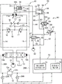
Fig. 1 is a diagram showing a hydraulic circuit for swing driving mounted on a construction machine according to embodiment 1 of the present invention.
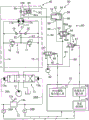
Fig. 2 is a diagram showing a hydraulic circuit for swing driving mounted on a construction machine according to embodiment 2 of the present invention.
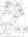
Fig. 3 is a diagram showing a hydraulic circuit for swing driving mounted on a construction machine according to embodiment 3 of the present invention.
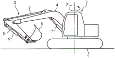
Fig. 4 is a side view of a hydraulic excavator corresponding to the construction machine according to embodiments 1 to 3.
Detailed Description
Preferred embodiments of the present invention will be described with reference to the accompanying drawings.
Fig. 4 shows a hydraulic excavator corresponding to the construction machine according to each embodiment. This hydraulic shovel includes: a crawler-type lower traveling body 1 constituting a base body; an upper slewing body 2 which is a slewing body to be carried in a freely slewing manner around a slewing center axis Z perpendicular to a traveling surface thereof; and an excavation attachment 3 attached to the upper slewing body 2. The excavation attachment 3 includes a boom 4 that is free to rise and fall, an arm 5 attached to a distal end of the boom 4, a bucket 6 attached to a distal end of the arm 5, and a boom cylinder 7, an arm cylinder 8, and a bucket cylinder 9, which are a plurality of hydraulic cylinders for operating the boom 4, the arm 5, and the bucket 6, respectively.
The construction machine according to the present invention is not limited to such a hydraulic excavator. The present invention is applicable to various construction machines (for example, slewing cranes) including a base and a slewing body that is mounted on the base and can slew. The base is not limited to a base that can travel, such as the lower traveling structure 1, and may be a base that is installed in a specific place and supports the revolving structure.
Fig. 1 shows a hydraulic circuit according to embodiment 1 of the present invention, which is an example of a circuit for slewing the upper slewing body 2. The circuit includes a hydraulic pump 10, a swing motor 11, a swing operation device 12, a control valve 13, a right swing pipe 14, a left swing pipe 15, a relief valve circuit 18, a check valve circuit 21, a communication passage 22, and a replenishment line 23.
The turning motor 11 is a hydraulic motor that is connected to, for example, a turning shaft portion 2a of the upper turning body 2 and performs the following operations: receiving the supply of the hydraulic oil, a slewing torque is applied to the upper slewing body 2 to slew the upper slewing body 2. Specifically, the swing motor 11 has a right swing port 11a connected to the right swing pipe 14 and a left swing port 11b connected to the left swing pipe 15, and when receiving the hydraulic oil supplied to the right swing port 11a, the swing motor applies a swing torque in a direction to cause the upper swing body 2 to perform a right swing operation to the upper swing body 2 as the hydraulic oil is discharged from the left swing port 11b, and when receiving the hydraulic oil supplied to the left swing port 11b, the swing motor applies a swing torque in a direction to cause the upper swing body 2 to perform a left swing operation to the upper swing body 2 as the hydraulic oil is discharged from the right swing port 11 a.
The hydraulic motor constituting the swing motor 11 is a variable displacement type hydraulic motor whose displacement (displacement) is variable. The slewing torque applied to the upper slewing body 2 by the slewing motor 11 increases as the capacity of the slewing motor 11 increases.
The hydraulic pump 10 is connected to an engine, not shown, mounted on the upper slewing body 2, and is driven by the engine to discharge hydraulic oil to be supplied to the slewing motor 11.
The swing operation device 12 and the control valve 13 constitute a swing control device. The swing control device allows the hydraulic pump 10 to supply hydraulic oil to the swing motor 11 and operates the swing motor 11 when a swing command operation for swinging the upper swing body 2 is received.
The control valve 13 is provided between the hydraulic pump 10 and the swing motor 11, and performs an operation of changing the direction and flow rate of the hydraulic oil supplied from the hydraulic pump 10 to the swing motor 11. The control valve 13 shown in fig. 1 is constituted by a pilot-operated three-position hydraulic switching valve having a right-turning pilot port 13a and a left-turning pilot port 13 b. When no pilot pressure is input to either of the pilot ports 13a and 13b, the control valve 13 keeps the neutral position, which is the center position in fig. 1, and blocks the two slewing pipes 14 and 15 from the hydraulic pump 10, thereby preventing the slewing motor 11 from slewing. On the other hand, when the pilot pressure is input to the right swing pilot port 13a, the control valve 13 is switched from the neutral position to a right swing position, which is the left position in fig. 1, by a stroke corresponding to the magnitude of the pilot pressure, and allows the hydraulic oil to be supplied from the hydraulic pump 10 to the right swing port 11a of the swing motor 11 through the right swing pipe 14 at a flow rate corresponding to the stroke, and allows the hydraulic oil discharged from the left swing port 11b to be returned to the tank through the left swing pipe 15. On the other hand, when the pilot pressure is input to the left swing pilot port 13b, the control valve 13 is switched from the neutral position to a left swing position, which is a right position in fig. 1, by a stroke corresponding to the magnitude of the pilot pressure, and allows the hydraulic oil to be supplied from the hydraulic pump 10 to the left swing port 11b of the swing motor 11 through the left swing pipe 15 at a flow rate corresponding to the stroke, and allows the hydraulic oil discharged from the right swing port 11a to be returned to the tank through the right swing pipe 14.
The swing operation device 12 has an operation lever 12a and a pilot valve 12 b. The operating lever 12a is an operating member, and when the operator applies the swing instruction operation to the operating lever 12a, the operating lever 12a is rotated in the direction thereof. The pilot valve 12B has an inlet end connected to a first-come hydraulic pressure source, not shown, and a pair of outlet ends connected to the right swing pilot port 13a and the left swing pilot port 13B of the control valve 13 via a right swing pilot line 26A and a left swing pilot line 26B, respectively. The pilot valve 12b is coupled to the control lever 12a and is opened to allow a pilot pressure corresponding to the magnitude of the swing command operation to be supplied from the pilot hydraulic pressure source to a pilot port corresponding to the direction of the swing command operation applied to the control lever 12a, of the right and left swing pilot ports 13a and 13 b.
The relief valve circuit 18, the check valve circuit 21, the communication passage 22, and the supply line 23 constitute a circuit for braking the swing motor 11 when the control valve 13 is returned to the neutral position. These circuits are not essential to the present invention.
The relief valve circuit 18 connects the right swing pipe 14 and the left swing pipe 15 to each other bypassing the swing motor 11. The relief valve circuit 18 includes a left rotary relief valve 16 and a right rotary relief valve 17. The left and right swing relief valves 17 are configured as follows: the inlet end of the left rotary overflow valve 16 is connected with the right rotary pipeline 14, the inlet end of the right rotary overflow valve 17 is connected with the left rotary pipeline 15, and the outlet ends of the left rotary overflow valve 1 and the right rotary overflow valve 17 are connected with each other.
The check valve circuit 21 connects the two swing pipes 14, 15 to each other at a position closer to the swing motor 11 than the relief valve circuit 18. The check valve circuit 21 includes a left rotary check valve 20 and a right rotary check valve 19. The left swing check valve 20 is disposed in a direction in which the working oil is prevented from flowing in from the left swing pipe 15, and the right swing check valve 19 is disposed in a direction in which the working oil is prevented from flowing in from the right swing pipe 14.
The communication passage 22 connects a portion of the relief valve circuit 18 located between the left swing relief valve 16 and the right swing relief valve 17 to a portion of the check valve circuit 21 located between the left swing check valve 20 and the right swing check valve 19. The makeup line 23 connects the communication path 22 and a tank to each other so that, when the communication path 22 is at a negative pressure, working oil is allowed to be sucked up from the tank to the communication path 22 through the makeup line 23 to prevent cavitation. A back pressure valve, not shown, is provided in the supply line 23.
In this circuit, for example, when the control lever 12a is returned to the neutral position during the right slewing drive and the control valve 13 is returned from the current right slewing position to the neutral position, the control valve 13 cuts off the connection between the two slewing pipes 14 and 15 and the hydraulic pump 10, but the slewing motor 11 continues to rotate in the right slewing direction due to the inertia of the upper slewing body 2. Thereby, the pressure of the left slewing pipe 15 on the outlet throttle side rises. When the pressure reaches the set pressure of the right swing relief valve 17, the right swing relief valve 17 opens to allow the hydraulic oil in the left swing pipe 15 to flow into the swing motor 11 through the right swing relief valve 17, the communication passage 22, the right swing check valve 19, and the right swing pipe 14. In this way, the swing motor 11 that continues to rotate by inertia receives a braking force generated by the action of the right swing relief valve 17, and the swing motor 11 is decelerated and stopped. The same applies to deceleration/stop in the case of left turn.
The hydraulic excavator further includes a swing parking brake 30, a brake switching device 40, a capacity operation unit 50, a hydraulic pressure supply control unit 60, a capacity pilot line 69, a pilot pressure operation valve 68, a right swing pilot sensor 28A, a left swing pilot sensor 28B, and a controller 70.
The swing parking brake 30 is a brake device that applies a mechanical stop holding force to the upper swing body 2 to hold the upper swing body 2 in a stopped state at least when the upper swing body 2 is not driven by the swing motor 11, that is, at least when the swing motor 11 is not applying a swing torque to the upper swing body 2. The swing parking brake 30 is switchable between a braking state in which the stop holding force is applied to the upper swing body 2 and a brake released state in which the upper swing body 2 is released to allow the upper swing body 2 to swing.
The swing parking brake 30 according to the present embodiment is a hydraulic passive brake, and is switched to the brake released state only when a brake release pressure is received, and is maintained in the brake released state when the brake release pressure is not received. Specifically, the swing parking brake 30 includes a hydraulic cylinder 32 having a spring chamber 32a as a first hydraulic chamber and a brake release chamber 32b as a second hydraulic chamber on the opposite side thereof, and a spring 34 filled in the spring chamber 32 a. When the brake release pressure is not supplied to the brake release chamber 32b, the swing parking brake 30 applies the stop holding force, which is a restraining force, to an appropriate portion of the upper swing body 2, for example, the swing shaft portion 2a shown in fig. 1, by the elastic force of the spring 34. On the other hand, when the brake release pressure is supplied to the brake release chamber 32b, the brake release pressure applies an urging force to the hydraulic cylinder 32 as a brake release force for releasing the application of the restraining force against the elastic force of the spring 34.
The brake switching device 40 switches the swing parking brake 30 between the braking state and the braking released state by supplying the braking released pressure and stopping supplying the braking released pressure to the swing parking brake 30. Specifically, the brake switching device 40 includes a pilot pump 42 connected to the brake release chamber 32b via a brake release line 44, and a brake switching valve 46 provided in the middle of the brake release line 44.
The pilot pump 42 discharges pilot oil under the drive of the engine. When the pilot oil is supplied to the brake release chamber 32b through the brake release line 44, the brake release pressure is generated in the brake release chamber 32 b.
The brake switch valve 46 is a two-position electromagnetic switch valve having an electromagnetic valve 48 in the present embodiment. The brake switching valve 46 is held at a closed position, which is a brake position on the left side in fig. 1, when a brake release command, which is an excitation current of the solenoid valve 48, is not input to the solenoid valve 48, and cuts off the brake release conduit 44 and cuts off supply of the brake release pressure from the pilot pump 42 to the brake release chamber 32b, and when the brake release command is input to the solenoid valve 48, switches to an open position, which is a brake release position on the right side in fig. 1, and turns on the brake release conduit 44 to allow supply of the brake release pressure from the pilot pump 42 to the brake release chamber 32 b.
The displacement operating unit 50 and the hydraulic pressure supply control unit 60 constitute a displacement control device together with the controller 70. This displacement control device controls the displacement of the swing motor 11, i.e., the displacement, by the hydraulic pressure in accordance with the swing command operation applied to the operating lever 12 a.
The displacement operation unit 50 changes the displacement of the swing motor 11 upon receiving the supply of the hydraulic pressure for displacement operation under the control of the hydraulic pressure supply control unit 60, and the displacement operation unit 50 includes a displacement operation cylinder 52 surrounding a piston chamber and a displacement operation piston 54 filled in the piston chamber of the displacement operation cylinder 52. The displacement operating piston 54 is axially displaceable while being slidable relative to the inner peripheral surface of the displacement operating cylinder 52 in the piston chamber, and is coupled to the swing motor 11 so as to change the displacement of the swing motor 11 in the axial direction. For example, when the rotary motor 11 is an axial piston motor, the inclination of the swash plate of the rotary motor 11 is changed.
Specifically, the displacement operating piston 54 is coupled to the swing motor 11 via a rod 53 extending from the displacement operating piston 54 through the first hydraulic chamber 55. The capacity operating piston 54 divides the interior of the piston chamber 52 into a first hydraulic chamber 55 and a second hydraulic chamber 56, and the capacity of the swing motor 11 increases with displacement in the direction in which the volume of the first hydraulic chamber 55 increases (displacement to the right in fig. 1). The axial position of the capacity operating piston 54 depends on the balance between the first capacity operating hydraulic pressure supplied to the first hydraulic chamber 55 and the second capacity operating hydraulic pressure supplied to the second hydraulic chamber 56. That is, the displacement operating piston 54 is displaced in a direction (rightward in fig. 1) in which the displacement of the swing motor 11 is increased as the second displacement operating hydraulic pressure is lower than the first displacement operating hydraulic pressure.
The pressure receiving area, which is the area of the capacity operation piston 54 that receives the capacity operation hydraulic pressure in the first hydraulic chamber 55, is smaller than the pressure receiving area in the second hydraulic chamber 56 by the cross-sectional area of the rod 53. The difference in cross-sectional area allows the displacement operation piston 54 to be held at a position where the volume of the second hydraulic chamber 56 is maximum, that is, a position where the displacement of the swing motor 11 is minimum, that is, a leftmost position in fig. 1, when the first displacement-operation hydraulic pressure and the second displacement-operation hydraulic pressure are equal to each other.
The hydraulic pressure supply control unit 60 controls the position of the displacement operating piston 54 by changing the magnitude balance between the first displacement operating hydraulic pressure and the second displacement operating hydraulic pressure, and controls the displacement of the swing motor 11 corresponding to the position. The hydraulic pressure supply control unit 60 according to the present embodiment is configured to supply the displacement operation hydraulic pressure to the displacement operation unit 50 by using the oil discharged from the pilot pump 42 of the brake switching device 40, and to change the displacement operation hydraulic pressure, and includes a hydraulic pressure supply line 61 and a hydraulic pressure supply control valve 62 shown in fig. 1.
The hydraulic pressure supply line 61 is connected to the pilot pump 42 in parallel with the brake switching valve 46, and supplies the displacement-operation hydraulic pressure to the first hydraulic chamber 55 and the second hydraulic chamber 56 of the displacement operation unit 50 by guiding the oil discharged from the pilot pump 42 to the displacement operation unit 50. Specifically, the hydraulic pressure supply line 61 branches off from the brake release line 44 at a position on the upstream side of the brake switching valve 46 in the brake switching device 40. The hydraulic pressure supply line 61 is branched into a first hydraulic line 65 connected to the first hydraulic chamber 55 and a second hydraulic line 66 connected to the second hydraulic chamber 56.
The hydraulic pressure supply control valve 62 is provided midway in the second hydraulic line 66 so that the second displacement operation hydraulic pressure supplied to the second hydraulic chamber 56 through the second hydraulic line 66 is lower than the first displacement operation hydraulic pressure supplied to the first hydraulic chamber 55 through the first hydraulic line 56 to an extent corresponding to the magnitude of the displacement pilot pressure applied to the hydraulic pressure supply control valve 62.
The hydraulic pressure supply control valve 62 according to the present embodiment is configured by a pilot-operated servo valve, and includes a sleeve 62a, a spool 62b slidably fitted in the sleeve 62a, a spring 63, and a pilot port 64. The spring 63 and the pilot port 64 are disposed on both axial sides of the spool 62 b. When the volume pilot pressure is not supplied to the pilot port 64, the spool 62b is held at a fully open position (left position in fig. 1) at which the second hydraulic line 66 is open, with a maximum opening area, by the elastic force of the spring 63. When the displacement pilot pressure is supplied to the pilot port 64, the spool 62b is displaced from the fully open position in the closing direction (leftward in fig. 1) by a stroke corresponding to the magnitude of the displacement pilot pressure, and the second displacement-operation hydraulic pressure supplied to the second hydraulic chamber 56 is lower than the first displacement-operation hydraulic pressure supplied to the first hydraulic chamber 55.
The displacement pilot line 69 guides the oil discharged from the pilot pump 42 of the brake switching device 40 to the pilot port 64 of the hydraulic pressure supply control valve 62, and supplies the displacement pilot pressure to the pilot port 64. That is, the displacement pilot line 69 has an upstream end connected to the brake release line 44 and a downstream end connected to the pilot port 64.
The pilot pressure operation valve 68 is provided in the middle of the capacity pilot conduit 69, and when receiving an input of a capacity command, opens at an opening corresponding to the magnitude of the capacity command, thereby changing the capacity pilot pressure supplied to the pilot port 64. The pilot pressure operation valve 68 according to the present embodiment is constituted by a proportional solenoid valve having a solenoid valve 67. The solenoid valve 67 receives supply of an exciting current as the capacity command. The pilot pressure operation valve 68 is closed when the field current is not supplied to the solenoid valve 67 (i.e., no capacity command is input), blocks the capacity pilot conduit 69 to connect the pilot port 64 to the tank, thereby preventing the capacity pilot pressure from being supplied to the pilot port 64, and is opened when the field current is supplied to the solenoid valve 67 (i.e., a capacity command is input), thereby opening the capacity pilot conduit 69 at an opening corresponding to the magnitude of the field current and allowing the capacity pilot pressure having the magnitude corresponding to the opening to be supplied to the pilot port 64.
As a feature of the present embodiment, an upstream end of the displacement pilot line 69 is connected to a portion of the brake release line 44 located on the downstream side of the brake selector valve 46. Therefore, when the brake switch valve 46 is switched to the brake position (left position in fig. 1), the pilot port 64 communicates with the tank regardless of whether the pilot pressure operation valve 68 is open or closed, and the supply of the volume pilot pressure to the pilot port 64 is blocked.
The right and left turn pilot sensors 28A and 28B generate pilot pressure detection signals corresponding to the right and left turn pilot pressures of the right and left turn pilot lines 26A and 26B, respectively, and input the pilot pressure detection signals to the controller 70. Therefore, the right swing pilot sensor 28A and the left swing pilot sensor 28B detect that a swing operation command is applied to the operating lever 12a of the swing operation device 12, and supply this information to the controller 70.
The controller 70 is constituted by a microcomputer, for example, and includes a brake release command input unit 72 and a capacity command input unit 74 shown in fig. 1 as functions relating to the present invention.
The brake release command input unit 72 constitutes a brake release command unit together with the right and left turn pilot sensors 28A and 28B. Specifically, when the right swing pilot sensor 28A or the left swing pilot sensor 28B detects that the swing operation device 12 is applied with the swing instruction operation, the brake release instruction input unit 72 opens the control valve 13 according to the swing instruction operation to allow the hydraulic pump 10 to supply the hydraulic oil to the swing motor 11, and then inputs the brake release instruction to the solenoid valve 48 of the brake switching valve 46 to switch the swing parking brake 30 from the braking state to the brake release state. The period from the time when the swing command operation is performed to the time when the swing parking brake 30 is switched to the brake released state (brake release time) is set to a very short time to the extent that the swing parking brake 30 can reliably hold the upper swing body 2 stationary during the period until the swing motor 11 is actually operated to swing the upper swing body 2. The extremely short time may be a time directly corresponding to a naturally occurring time lag between the time when the right swing pilot pressure sensor 28A or the right swing pilot pressure sensor 28B detects the swing command operation and the time when the brake switch valve 46 is actually switched to the brake release position. Alternatively, a timer may be provided in the brake release command input unit 72, and the brake release command may be input to the electromagnetic valve 48 of the brake selector valve 46 after the lapse of the very short time period set in advance from the time when the swing command operation is detected.
The larger the slewing speed of the upper slewing body 2 (i.e., the operating speed of the slewing motor 11) specified by the slewing command operation is, the larger the capacity command generated by the capacity command input unit 74 is, and the capacity command is input to the solenoid valve 67 of the pilot pressure operation valve 68. That is, the capacity command input unit 74 generates and inputs a capacity command for increasing the capacity pilot pressure applied to the pilot port 64 of the hydraulic pressure supply control valve 62 as the swing speed corresponding to the swing command operation increases.
Next, the operation of the hydraulic circuit will be described.
When the control lever 12a of the swing operation device 12 is at the neutral position, the pilot pressure is not supplied to both the right swing pilot port 13a and the left swing pilot port 13b of the control valve 13, and the control valve 13 is held at the neutral position. Therefore, the swing motor 11 does not apply a swing torque to the upper swing body 2. On the other hand, the brake release command input unit 72 of the controller 70 does not input a brake release command to the electromagnetic valve 48 of the brake switch valve 46, and holds the brake switch valve 46 at the closed position, that is, the brake position. The brake switching valve 46 at this braking position cuts off the brake release line 44, and communicates the brake release chamber 32b of the swing parking brake 30, which is a passive brake, with the oil tank, thereby holding the swing parking brake 30 in a braking state, that is, a state in which a stop holding force is applied to the upper swing body 2.
Thus, the displacement control means maintains the displacement of the swing motor 11 at the minimum displacement while the brake switching means 40 maintains the swing parking brake 30 in the braking state. The displacement pilot line 69 connected to the brake release line 44 at a position on the downstream side of the brake selector valve 48 (i.e., on the opposite side of the pilot port 42) communicates with the tank through the brake selector valve 48 at the braking position, and input of the displacement pilot pressure to the pilot port 64 of the hydraulic pressure supply control valve 62 is prevented regardless of the degree of opening of the pilot pressure operation valve 68. Accordingly, the hydraulic pressure supply control valve 62 is held at the full open position, and the second operation hydraulic pressure supplied to the second hydraulic chamber 56 of the displacement operation portion 50 is kept equal to the first operation hydraulic pressure supplied to the first hydraulic chamber 55. The capacity operating piston 54 is held at a position (leftmost position in fig. 1) where the capacity of the second hydraulic chamber 56 is maximum, by the difference between the pressure receiving area in the second hydraulic chamber 56 and the pressure receiving area in the first hydraulic chamber 55, and the capacity of the swing motor 11 is held at the minimum capacity.
When the control lever 12a is operated by a swing command and is rotated in a right swing operation direction or a left swing operation direction, which is a specific operation direction, from the neutral position, a pilot pressure is supplied from the pilot valve 12B of the swing operation device 12 through the pilot conduit 26A (or 26B) to a pilot port corresponding to the specific operation direction, of the right swing pilot port 13a and the left swing pilot port 13B of the control valve 13. Accordingly, the control valve 13 is switched to the position corresponding to the direction in the right and left swing positions, allowing the hydraulic pump 10 to supply the hydraulic oil to the right swing port 11a or the left swing port 11b of the swing motor 11. The turning motor 11 applies a rotational torque in a direction corresponding to a port that receives the supply of the hydraulic oil to the upper turning body 2.
At this time, the brake switching valve 46 remains at the closed position (brake position), the pilot pump 42 is prevented from supplying the pilot oil to the brake release chamber 32b of the hydraulic cylinder 32 in the swing parking brake 30 through the brake release line 44, and the pilot port 64 of the hydraulic pressure supply control valve 62 is communicated with the tank, so that the capacity of the swing motor 11 is kept at the minimum capacity. Thus, the turning torque applied to the upper turning body 2 by the turning motor 11 can be limited to a smaller torque by preventing an increase in the stop holding force (torque) generated by the turning parking brake 30. Accordingly, it is possible to prevent the swing start caused by so-called slip of the swing parking brake 30 due to the start of the swing at the maximum torque even though the swing parking brake 30 is in the braking state.
As the pilot pressure is generated, the right or left turn pilot sensor 28A or 28B generates a pilot pressure detection signal and inputs the signal to the controller 70. When the detected pilot pressure is equal to or higher than a predetermined determination value, the brake release command input unit 72 determines that the swing command operation is applied to the operation lever 12a, and after a predetermined extremely short time has elapsed since the determination, inputs a brake release command to the electromagnetic valve 48 of the brake switch valve 46 to open the brake switch valve 46. The thus opened brake switching valve 46 allows the pilot pump 42 to supply the pilot oil to the brake release chamber 32b of the hydraulic cylinder 32 in the swing parking brake 30 through the brake release line 44, switches the swing parking brake 30 from the current braking state to the brake release state, and at the same time, allows the oil discharged from the pilot pump 42 to be introduced into the pilot port 64 of the hydraulic pressure supply control valve 62 through the brake release line 44 and the capacity pilot line 69, thereby allowing the capacity of the swing motor 11 to increase from the minimum capacity to the maximum capacity by opening the pilot pressure operation valve 68.
Allowing the capacity of the swing motor 11 to increase, that is, releasing the prohibition of the increase enables the upper swing body 2 to be started with a swing torque that increases in accordance with a swing command operation applied to the operation lever 12a by an operator, so that the swing speed can be rapidly increased regardless of the number of times the upper swing body 2 is multiple. Further, since the increase (release prohibition) of the turning torque and the switching of the turning parking brake 30 to the brake released state are surely synchronized with the opening of the brake switching valve 46, it is possible to prevent the turning parking brake 30 or other devices from being damaged due to the slipping of the turning parking brake 30 caused by applying an excessive torque (for example, a torque much larger than a torque corresponding to the minimum capacity of the turning motor 11 such as the maximum torque) to the upper turning body 2 even though the turning parking brake 30 is in the brake state.
The synchronization of the permission of the increase of the slewing torque and the switching to the brake release state means that the coincidence between the brake release timing and the start timing of the permission of the increase (release prohibition) of the slewing torque is such that the slewing of the upper slewing body 2 due to a so-called slip of the slewing parking brake 30 caused by the increase of the slewing torque before the slewing parking brake 30 is switched from the brake state to the brake release state can be reliably prevented. Therefore, the term "synchronization" as used herein also includes a case where the two timings are slightly deviated within a range in which the slewing accompanying the slip can be reliably prevented.
In embodiment 1, as described above, the displacement pilot conduit 69 branches off from the brake release conduit 44 at a position downstream of the brake switching valve 46, in other words, the upstream end of the displacement pilot conduit 69 is connected to the brake release conduit 44 at a position downstream of the brake switching valve 46, and thus the brake release of the swing parking brake 30 and the allowable swing torque increase can be reliably synchronized with each other with a simple configuration. For example, even if the timing at which the displacement command input unit 74 inputs the displacement command for increasing the pilot pressure to the pilot pressure operation valve 68 precedes the timing at which the brake release command input unit 72 inputs the brake release command to the brake switch valve 46 (brake release timing) after the swing command operation is applied to the operation lever 12a, the timing at which the displacement increase is actually allowed (that is, the timing at which the pilot pressure is supplied to the pilot port 64 of the hydraulic pressure supply control valve 62) can be reliably synchronized with the brake release timing.
However, the present invention is not limited to embodiment 1. The present invention also includes a mode in which the displacement pilot pipe 69 branches off from the upstream side of the brake selector valve, for example. Fig. 2 shows embodiment 2 as an example of this method.
The displacement pilot line 69 according to embodiment 2 branches from the brake release line 44 to the first hydraulic line 65 of the hydraulic pressure supply control unit 60 on the upstream side of the brake switching valve 46. That is, the upstream end of the displacement pilot conduit 69 is directly connected to the pilot pump 42 without passing through the brake switching valve 46, and the displacement pilot conduit 69 directly guides the oil discharged from the pilot pump 42 to the pilot port 64 of the hydraulic pressure supply control valve 62.
On the other hand, the controller 70 includes a capacity limiting unit 76 in addition to the brake release command input unit 72 and the capacity command input unit 74, which are the same as the brake release command input unit 72 and the capacity command input unit 74 according to embodiment 1. The capacity limiting unit 76 inputs a capacity limiting command for limiting the capacity of the swing motor 11 to the minimum capacity to the capacity command input unit 74 at least at a time when a predetermined extremely short time has elapsed after the swing command operation is applied to the operating lever 12a, that is, before a brake release time when the brake release command input unit 72 inputs the brake release command to the brake switching valve 46, and releases the capacity limiting command at the same time as the brake release time or after a predetermined extremely short time has elapsed from the brake release time. When the capacity command input unit 74 receives the input of the capacity limit command, the input of the capacity command to the pilot pressure operation valve 68 is stopped regardless of the turning command operation, and the capacity of the turning motor 11 is maintained at the minimum capacity.
In embodiment 2, the pilot pump 40 of the brake switching device 40 may be used as a device for causing the capacity control device to perform the capacity increasing operation, thereby reducing the number of components. The capacity restriction unit 76 can prevent so-called slip of the swing parking brake 30 as in the above embodiment 1 by synchronizing the brake release timing, that is, the timing at which the swing parking brake 30 is switched to the brake released state, with the permission of the capacity increase (release prohibition) of the swing motor 11.
The present invention is not limited to the embodiment in which the pilot pump of the brake switching device is used as the device for increasing the capacity of the swing motor. That is, the present invention also includes a manner of including a hydraulic pressure source other than the pilot pump for increasing the capacity of the swing motor.
The pilot pump 42 is not necessarily required to supply the displacement operation hydraulic pressure to the displacement operation portion 50, and the displacement operation hydraulic pressure may be applied to the displacement operation portion 50 by a pump other than the pilot pump 42. Alternatively, as in embodiment 3, as shown in fig. 3, the upstream end of the hydraulic pressure supply line 61 of the hydraulic pressure supply control unit 60 may be connected to a portion of the brake release line 44 located on the downstream side of the brake switching valve 46. In this case, it is more preferable that a check valve 82 is provided in the hydraulic pressure supply line 61 to prevent the reverse flow of the hydraulic oil from the displacement operating unit 50 to the brake release line 44. The check valve 82 can maintain the volume-operating hydraulic pressure applied to the volume operating unit 50 even at a position where the brake switch valve 46 is switched to the brake position, that is, at a position where the brake release line 44 is blocked and the brake release chamber 32b is communicated with the tank.
As described above, the present invention provides a rotary working machine including a rotary body and a rotation parking brake for holding the rotary body in a stopped state, capable of reliably holding the rotary body in the stopped state by the rotation parking brake before a rotation torque is applied to the rotary body, and capable of quickly raising a rotation speed after the start of rotation, and capable of reliably protecting the rotation parking brake and other devices from the influence of the rotation torque.
The present invention provides a rotary working machine comprising: a substrate; a rotator which is mounted on the base and can rotate; a slewing motor configured from a variable displacement hydraulic motor, and configured to apply a slewing torque for slewing the slewing body to the slewing body by receiving a supply of hydraulic oil; a capacity control device that controls a capacity of the swing motor; a hydraulic pump that discharges hydraulic oil to be supplied to the swing motor; a swing control device that allows the hydraulic fluid to be supplied from the hydraulic pump to the swing motor and operates the swing motor by receiving a swing command operation for swinging the swing body; a swing parking brake that is switchable between a braking state in which a stop holding force is applied to the swing body to hold the swing body in a stopped state and a brake release state in which the swing body is released to allow the swing body to swing; a brake switching device that switches the swing parking brake between the braking state and the brake release state; a brake release command unit configured to input a brake release command to the brake switching device to switch the swing parking brake from the braking state to the brake released state after the swing control device receives the swing command operation and allows the hydraulic oil to be supplied from the hydraulic pump to the swing motor; and a capacity limiting unit that limits a capacity of the swing motor controlled by the capacity control device, wherein the capacity limiting unit limits the capacity of the swing motor controlled by the capacity control device to a capacity equal to or less than a preset brake release capacity until a brake release timing at which the swing parking brake is switched to the brake release state by inputting a brake release command to the brake switching device after the swing control device receives the swing command operation to allow the hydraulic oil to be supplied from the hydraulic pump to the swing motor, and allows the capacity control device to increase the capacity of the swing motor until the capacity exceeds the brake release capacity after the brake release timing.
In the slewing type construction machine, the brake release instructing unit inputs a brake release instruction to the brake switching device to switch the slewing parking brake from the braking state to the brake release state after the slewing control device receives the slewing instruction operation and starts the supply of the hydraulic oil from the hydraulic pump to the slewing motor, and therefore the slewing body can be reliably kept in the stopped state until the slewing torque is applied to the slewing body. The capacity limiting unit limits the capacity of the slewing motor to a capacity equal to or less than a preset braking release capacity (preferably, a minimum capacity of the slewing motor) at least before the braking release time, and allows the capacity of the slewing motor to increase beyond the braking release capacity after the braking release time, thereby reliably preventing the slewing parking brake from being damaged due to excessive torque being applied to the slewing body in a braking state in which the slewing parking brake applies a stop holding force to the slewing body, and increasing the capacity of the slewing motor to rapidly increase the slewing speed of the slewing body after the braking state is released.
In the case where the turning command operation is an operation for specifying a turning speed of the turning body, it is preferable that the capacity control device increases the capacity of the turning motor as the turning speed specified by the turning command operation increases, and the capacity restriction unit restricts the capacity of the turning motor to a capacity equal to or less than the braking cancellation capacity regardless of the turning speed specified by the turning command operation before the braking cancellation time. According to the above configuration, the slip before the brake release timing can be prevented, and after the brake release timing, the acceleration for the swing start can be performed to an extent corresponding to the swing command operation.
As a specific configuration of the brake mechanism in the rotary working machine, in a case where the rotary parking brake is a hydraulic passive brake that maintains the braking state when the supply of the brake release pressure is not received and switches to the brake release state only when the supply of the brake release pressure is received, it is preferable that the brake switching device includes: a pilot pump that discharges pilot oil that is supplied to the swing parking brake through a brake release line to cause the swing parking brake to generate the brake release pressure; and a brake switching valve provided midway in the brake release line, capable of switching between a braking position at which the rotary parking brake is brought into the brake released state by allowing the pilot oil to be supplied to the rotary parking brake by opening the brake release line and a brake release position at which the rotary parking brake is brought into the brake released state by cutting off the supply of the pilot oil to the rotary parking brake by cutting off the brake release line, and switching to the brake released position upon receiving an input of the brake release command.
In this case, it is preferable that the capacity control device includes: a displacement operation unit that is operated by receiving a supply of a hydraulic pressure for displacement operation to change a displacement of the swing motor; a hydraulic pressure supply control unit that receives a supply of a capacity pilot pressure and changes a manner of supplying the capacity-operation hydraulic pressure to the capacity operation unit such that a capacity of the swing motor increases as the capacity pilot pressure increases; a displacement pilot line configured to apply the displacement pilot pressure by guiding the pilot oil discharged from the pilot pump to the displacement operation unit; a pilot pressure operation valve that is provided in the middle of the capacity pilot conduit, that opens at an opening degree corresponding to a capacity command when the pilot pressure operation valve receives the input of the capacity command, and that opens so as to increase the capacity pilot pressure applied to the capacity operation portion through the capacity pilot conduit; and a capacity command input unit that inputs the capacity command to the pilot pressure operation valve. The volume pilot line and the pilot pressure operation valve can supply and control the volume pilot pressure to the hydraulic pressure supply control unit by a pilot pump included in the brake switching device.
Preferably, the displacement pilot line is connected to a portion of the brake release line located on a downstream side of the brake selector valve. Thus, the displacement pilot line blocks the supply of the displacement pilot pressure to the displacement operating unit even when the brake switch valve is located at the brake position and the supply of the pilot oil is blocked, and the displacement of the swing motor can be reliably made to the minimum displacement regardless of the operation of the pilot pressure operating valve. That is, the capacity pilot conduit constitutes the capacity restricting section together with the brake switching valve of the brake switching device, and is interlocked with the brake switching valve to reliably perform capacity restriction and release thereof. The capacity limiter can be configured by the brake switching valve of the brake switching device and the capacity pilot conduit of the capacity control device without increasing the number of components.
More specifically, it is preferable that the capacity operating unit of the capacity control device includes: a displacement operation cylinder forming a piston chamber receiving the supply of the displacement operation hydraulic pressure; and a capacity operating piston that divides the piston chamber into a first hydraulic chamber and a second hydraulic chamber and has a shape in which a pressure receiving area in the second hydraulic chamber is larger than a pressure receiving area in the first hydraulic chamber, wherein the capacity operating piston is coupled to the swing motor such that a capacity of the swing motor decreases as a volume of the second hydraulic chamber is displaced in an increasing direction, the hydraulic pressure supply control unit includes a hydraulic pressure supply control valve that operates in response to supply of the capacity pilot pressure, and the hydraulic pressure supply control valve relatively decreases a capacity operating hydraulic pressure supplied to the second hydraulic chamber to a degree corresponding to a magnitude of the capacity pilot pressure with respect to a capacity operating hydraulic pressure supplied to the first hydraulic chamber by receiving the supply of the capacity pilot pressure, and when the supply of the capacity pilot pressure is not received, the displacement control piston is displaced to a position at which the displacement of the swing motor is minimized by a difference between a pressure receiving area of the first hydraulic chamber and a pressure receiving area of the second hydraulic chamber by equalizing a displacement operating hydraulic pressure supplied to the second hydraulic chamber and a displacement operating hydraulic pressure supplied to the first hydraulic chamber. In the displacement control device, the supply of the displacement pilot pressure to the hydraulic pressure supply control valve is cut off in a brake operating state, so that the displacement of the swing motor is reliably maintained at a minimum displacement by a difference in pressure receiving area between the second hydraulic chamber of the displacement operating portion and the displacement operating piston of the first hydraulic chamber.
Claims (6)
1. A rotary working machine, comprising:
a substrate;
a rotator which is mounted on the base and can rotate;
a slewing motor configured from a variable displacement hydraulic motor, and configured to apply a slewing torque for slewing the slewing body to the slewing body by receiving a supply of hydraulic oil;
a capacity control device that controls a capacity of the swing motor;
a hydraulic pump that discharges hydraulic oil to be supplied to the swing motor;
a swing control device that allows the hydraulic fluid to be supplied from the hydraulic pump to the swing motor and operates the swing motor by receiving a swing command operation for swinging the swing body;
a swing parking brake that is switchable between a braking state in which a stop holding force is applied to the swing body to hold the swing body in a stopped state and a brake release state in which the swing body is released to allow the swing body to swing;
a brake switching device that switches the swing parking brake between the braking state and the brake release state;
a brake release command unit configured to input a brake release command to the brake switching device to switch the swing parking brake from the braking state to the brake released state after the swing control device receives the swing command operation and allows the hydraulic oil to be supplied from the hydraulic pump to the swing motor; and the number of the first and second groups,
a capacity limiting unit that limits a capacity of the swing motor controlled by the capacity control device,
the displacement limiting unit limits the displacement of the swing motor controlled by the displacement control device to a preset displacement for brake release or less until a brake release timing at which the swing parking brake is switched to the brake release state by inputting a brake release command to the brake switching device after the swing control device receives the swing command operation to allow the hydraulic oil to be supplied from the hydraulic pump to the swing motor, and allows the displacement control device to increase the displacement of the swing motor until the displacement exceeds the brake release displacement after the brake release timing.
2. The rotary working machine according to claim 1, wherein:
the braking release capacity is a minimum capacity of the swing motor.
3. The rotary working machine according to claim 1 or 2, wherein:
the swing command operation is an operation for specifying a swing speed of the swing structure, the capacity control device increases a capacity of the swing motor as the swing speed specified by the swing command operation increases, and the capacity limiting unit limits the capacity of the swing motor to a capacity equal to or less than the braking-release capacity, regardless of the swing speed specified by the swing command operation, up to the braking-release time.
4. The rotary working machine according to claim 1 or 2, wherein:
the swing parking brake is a hydraulic passive brake that maintains the braking state when the supply of the brake release pressure is not received, switches to the brake release state only when the supply of the brake release pressure is received,
the brake switching device includes:
a pilot pump that discharges pilot oil that is supplied to the swing parking brake through a brake release line to cause the swing parking brake to generate the brake release pressure; and
a brake switching valve provided midway in the brake release line and capable of switching between a braking position at which the swing parking brake is brought into the brake released state by allowing the pilot oil to be supplied to the swing parking brake by opening the brake release line and a brake release position at which the swing parking brake is brought into the braking state by cutting off the supply of the pilot oil to the swing parking brake by cutting off the brake release line, and switching to the brake release position upon receiving an input of the brake release command,
the capacity control device includes:
a displacement operation unit that is operated by receiving a supply of a hydraulic pressure for displacement operation to change a displacement of the swing motor;
a hydraulic pressure supply control unit that receives a supply of a capacity pilot pressure and changes a manner of supplying the capacity-operation hydraulic pressure to the capacity operation unit such that a capacity of the swing motor increases as the capacity pilot pressure increases;
a displacement pilot line configured to apply the displacement pilot pressure by guiding the pilot oil discharged from the pilot pump to the displacement operation unit;
a pilot pressure operation valve that is provided in the middle of the capacity pilot conduit, that opens at an opening degree corresponding to a capacity command when the pilot pressure operation valve receives the input of the capacity command, and that opens so as to increase the capacity pilot pressure applied to the capacity operation portion through the capacity pilot conduit; and
and a capacity command input unit configured to input the capacity command to the pilot pressure operation valve.
5. The rotary working machine according to claim 4, wherein:
the capacity pilot line is connected to a portion of the brake release line located on a downstream side of the brake selector valve, and thereby constitutes the capacity limiter together with the brake selector valve.
6. The rotary working machine according to claim 4, wherein:
the capacity operation unit of the capacity control device includes:
a displacement cylinder forming a piston chamber receiving the supply of the displacement-operation hydraulic pressure; and
a capacity operating piston that divides the piston chamber into a first hydraulic chamber and a second hydraulic chamber, and has a shape in which a pressure receiving area in the second hydraulic chamber is larger than a pressure receiving area in the first hydraulic chamber, wherein,
the capacity operation piston is coupled to the swing motor such that a capacity of the swing motor decreases as a volume of the second hydraulic chamber is displaced in an increasing direction,
the hydraulic pressure supply control unit includes a hydraulic pressure supply control valve that is operated by receiving the supply of the displacement pilot pressure,
the hydraulic pressure supply control valve receives the supply of the displacement pilot pressure to relatively reduce the displacement operating hydraulic pressure supplied to the second hydraulic chamber with respect to the displacement operating hydraulic pressure supplied to the first hydraulic chamber to an extent corresponding to the magnitude of the displacement pilot pressure, and when the supply of the displacement pilot pressure is not received, equalizes the displacement operating hydraulic pressure supplied to the second hydraulic chamber with the displacement operating hydraulic pressure supplied to the first hydraulic chamber, thereby displacing the displacement operating piston to a position at which the displacement of the swing motor is minimized, utilizing the difference between the pressure receiving area of the first hydraulic chamber and the pressure receiving area of the second hydraulic chamber.
Applications Claiming Priority (3)
| Application Number | Priority Date | Filing Date | Title |
|---|---|---|---|
| JP2017215634A JP6981186B2 (en) | 2017-11-08 | 2017-11-08 | Swivel work machine |
| JP2017-215634 | 2017-11-08 | ||
| PCT/JP2018/038104 WO2019093070A1 (en) | 2017-11-08 | 2018-10-12 | Pivoting work machine |
Publications (2)
| Publication Number | Publication Date |
|---|---|
| CN111247296A CN111247296A (en) | 2020-06-05 |
| CN111247296B true CN111247296B (en) | 2022-04-01 |
Family
ID=66437896
Family Applications (1)
| Application Number | Title | Priority Date | Filing Date |
|---|---|---|---|
| CN201880069687.0A Active CN111247296B (en) | 2017-11-08 | 2018-10-12 | Rotary type construction machine |
Country Status (5)
| Country | Link |
|---|---|
| US (1) | US11131081B2 (en) |
| EP (1) | EP3690149B1 (en) |
| JP (1) | JP6981186B2 (en) |
| CN (1) | CN111247296B (en) |
| WO (1) | WO2019093070A1 (en) |
Families Citing this family (2)
| Publication number | Priority date | Publication date | Assignee | Title |
|---|---|---|---|---|
| JP7377022B2 (en) * | 2019-08-23 | 2023-11-09 | 川崎重工業株式会社 | Construction machinery hydraulic system |
| CN115012467B (en) * | 2022-06-17 | 2023-12-19 | 山河智能装备股份有限公司 | Excavator rotary platform and working device action matching control system |
Citations (4)
| Publication number | Priority date | Publication date | Assignee | Title |
|---|---|---|---|---|
| JP2000145711A (en) * | 1998-11-10 | 2000-05-26 | Uchida Hydraulics Co Ltd | Method and device for controlling turning system hydraulic device |
| JP5304236B2 (en) * | 2008-12-26 | 2013-10-02 | コベルコ建機株式会社 | Swivel brake device for construction machinery |
| CN103502540A (en) * | 2011-05-02 | 2014-01-08 | 神钢建设机械株式会社 | Rotation-type working machine |
| CN103562565A (en) * | 2011-05-25 | 2014-02-05 | 神钢建设机械株式会社 | Rotary work machine |
Family Cites Families (12)
| Publication number | Priority date | Publication date | Assignee | Title |
|---|---|---|---|---|
| JPH0535184Y2 (en) * | 1987-01-30 | 1993-09-07 | ||
| GB2204652B (en) | 1987-05-09 | 1991-05-15 | Kubota Ltd | Fluid pressure control circuit for working vehicle having transmission operable by fluid pressure |
| JPH065934Y2 (en) * | 1987-05-09 | 1994-02-16 | 株式会社クボタ | Parking brake operation part of work vehicle |
| JP2519147Y2 (en) * | 1989-05-25 | 1996-12-04 | 帝人製機 株式会社 | Hydraulic circuit for traveling |
| JP3544810B2 (en) * | 1997-01-08 | 2004-07-21 | 日立建機株式会社 | Locking / unlocking device for revolving superstructure of construction machinery |
| JP5351471B2 (en) | 2008-09-12 | 2013-11-27 | 住友建機株式会社 | Drive device for work machine |
| JP5242359B2 (en) * | 2008-12-10 | 2013-07-24 | 住友建機株式会社 | Swiveling drive control device |
| KR101763281B1 (en) | 2010-12-07 | 2017-07-31 | 볼보 컨스트럭션 이큅먼트 에이비 | Swing control system for hybrid construction machine |
| JP5683361B2 (en) | 2011-04-01 | 2015-03-11 | 日立建機株式会社 | Hydraulic drive device for work machine |
| US8752373B2 (en) | 2011-05-02 | 2014-06-17 | Kobelco Construction Machinery Co., Ltd. | Slewing type working machine |
| JP6693842B2 (en) * | 2016-09-08 | 2020-05-13 | 住友重機械建機クレーン株式会社 | crane |
| US10422361B2 (en) * | 2016-12-14 | 2019-09-24 | Cnh Industrial America Llc | Regenerative energy capturing and launching assistant |
-
2017
- 2017-11-08 JP JP2017215634A patent/JP6981186B2/en active Active
-
2018
- 2018-10-12 US US16/759,872 patent/US11131081B2/en active Active
- 2018-10-12 EP EP18876294.2A patent/EP3690149B1/en active Active
- 2018-10-12 WO PCT/JP2018/038104 patent/WO2019093070A1/en unknown
- 2018-10-12 CN CN201880069687.0A patent/CN111247296B/en active Active
Patent Citations (4)
| Publication number | Priority date | Publication date | Assignee | Title |
|---|---|---|---|---|
| JP2000145711A (en) * | 1998-11-10 | 2000-05-26 | Uchida Hydraulics Co Ltd | Method and device for controlling turning system hydraulic device |
| JP5304236B2 (en) * | 2008-12-26 | 2013-10-02 | コベルコ建機株式会社 | Swivel brake device for construction machinery |
| CN103502540A (en) * | 2011-05-02 | 2014-01-08 | 神钢建设机械株式会社 | Rotation-type working machine |
| CN103562565A (en) * | 2011-05-25 | 2014-02-05 | 神钢建设机械株式会社 | Rotary work machine |
Also Published As
| Publication number | Publication date |
|---|---|
| EP3690149B1 (en) | 2022-04-13 |
| CN111247296A (en) | 2020-06-05 |
| JP2019085791A (en) | 2019-06-06 |
| WO2019093070A1 (en) | 2019-05-16 |
| US11131081B2 (en) | 2021-09-28 |
| US20200340211A1 (en) | 2020-10-29 |
| JP6981186B2 (en) | 2021-12-15 |
| EP3690149A4 (en) | 2020-12-02 |
| EP3690149A1 (en) | 2020-08-05 |
Similar Documents
| Publication | Publication Date | Title |
|---|---|---|
| EP2706151B1 (en) | Slewing type working machine | |
| EP2706150B1 (en) | Rotation-type working machine | |
| EP3106677B1 (en) | Hydraulic drive appraratus for construction machine | |
| EP2863065B1 (en) | Construction-machinery hydraulic circuit, and control device therefor | |
| JP6335093B2 (en) | Hydraulic drive system for construction machinery | |
| JPH0448962B2 (en) | ||
| CN109563854B (en) | Valve device and fluid pressure system equipped with the same | |
| CN111247296B (en) | Rotary type construction machine | |
| US20190169819A1 (en) | Shovel and control valve for shovel | |
| KR101763283B1 (en) | Hydraulic pressure control device for construction machinery | |
| WO2016092809A1 (en) | Hydraulic drive system for construction machinery | |
| KR102543030B1 (en) | work machine | |
| JP2018054031A (en) | Hydraulic control device for work vehicle | |
| JP2005195131A (en) | Construction machine | |
| KR20200103538A (en) | Controller and construction machine | |
| EP3967884B1 (en) | Hydraulic control device for work machine | |
| WO2019004156A1 (en) | Hydraulic drive system | |
| JP4017812B2 (en) | Hydraulic circuit and crane with counterbalance valve | |
| JPH0637091Y2 (en) | Hydraulic drive for civil engineering and construction machinery | |
| JP6381228B2 (en) | Hydraulic drive | |
| JPH09165782A (en) | Swing brake control circuit for construction machine |
Legal Events
| Date | Code | Title | Description |
|---|---|---|---|
| PB01 | Publication | ||
| PB01 | Publication | ||
| SE01 | Entry into force of request for substantive examination | ||
| SE01 | Entry into force of request for substantive examination | ||
| GR01 | Patent grant | ||
| GR01 | Patent grant |